


3800
Table of contents
 Loading...
Aruba 2930M Switches
Installation and Getting Started Guide
Part Number: 5200-2809a
Published: September 2017
Edition: 2

©
Copyright 2017 Hewlett Packard Enterprise Development L.P.
Notices
The information contained herein is subject to change without notice. The only warranties for Hewlett Packard
Enterprise products and services are set forth in the express warranty statements accompanying such products
and services. Nothing herein should be construed as constituting an additional warranty. Hewlett Packard
Enterprise shall not be liable for technical or editorial errors or omissions contained herein.
Confidential computer software. Valid license from Hewlett Packard Enterprise required for possession, use, or
copying. Consistent with FAR 12.211 and 12.212, Commercial Computer Software, Computer Software
Documentation, and Technical Data for Commercial Items are licensed to the U.S. Government under vendor's
standard commercial license.
Links to third-party websites take you outside the Hewlett Packard Enterprise website. Hewlett Packard Enterprise
has no control over and is not responsible for information outside the Hewlett Packard Enterprise website.
Acknowledgments
Intel®, Itanium®, Pentium®, Intel Inside®, and the Intel Inside logo are trademarks of Intel Corporation in the United
States and other countries.
Microsoft® and Windows® are either registered trademarks or trademarks of Microsoft Corporation in the United
States and/or other countries.
Adobe® and Acrobat® are trademarks of Adobe Systems Incorporated.
Java® and Oracle® are registered trademarks of Oracle and/or its affiliates.
UNIX® is a registered trademark of The Open Group.
Applicable products
Aruba 2930M 24G 1-slot Switch JL319A
Aruba 2930M 24G PoE+ 1-slot Switch JL320A
Aruba 2930M 48G 1-slot Switch JL321A
Aruba 2930M 48G PoE+ 1-slot Switch JL322A
Aruba 2930M 40G 8SR PoE+ 1-slot Switch JL323A
Aruba 2930M 24SR PoE+ 1-slot Switch JL324A
Aruba 2930 2-port Stacking Module JL325A
Aruba 3810M/2930M 1-Port QSFP+ 40GbE Module JL078A
Aruba 3810M/2930M 4 HPE Smart Rate 1G/2.5G/5G/10G PoE+ Module JL081A
Table Continued

Aruba 3810M/2930M 4-Port 100M/1G/10G SFP+ MACsec Module JL083A
Aruba X371 12VDC 250W 100-240VAC Power Supply JL085A
Aruba X372 54VDC 680W 100-240VAC Power Supply JL086A
Aruba X372 54VDC 1050W 110-240VAC Power Supply JL087A
Related publications
• Aruba 2930M Switches Installation and Getting Started Guide
• Aruba 2930M and 3810M Switch Power Supply Quick Setup Guide and Safety/Regulatory Information
• HPE ArubaOS-Switch Power Over Ethernet (PoE/PoE+) Planning and Implementation Guide
• HPE ArubaOS-Switch Transceiver Guide
To view and download these publications, visit http://www.hpe.com/support/manuals.

Contents
Chapter 1 Introducing the 2930M switches................................................... 7
Front of the switches..................................................................................................................................8
Network ports.................................................................................................................................. 9
Management ports.........................................................................................................................11
Console Ports..................................................................................................................... 11
Auxiliary (Aux) port............................................................................................................. 12
Switch and port LEDs on front of the switches..............................................................................12
LED mode select button and indicator LEDs................................................................................ 18
Reset and Clear buttons............................................................................................................... 19
Out-of-band management (OOBM) port....................................................................................... 20
Back of the switches................................................................................................................................ 20
Power supplies..............................................................................................................................21
Power connector........................................................................................................................... 21
Stacking module slot..................................................................................................................... 21
Uplink port slot and module support..............................................................................................21
LEDs on the back of the switches................................................................................................. 22
2930M stacking module........................................................................................................................... 23
Stacking module LEDs..................................................................................................................24
2930M uplink modules............................................................................................................................. 26
Uplink module LEDs......................................................................................................................26
Switch features........................................................................................................................................ 28
Chapter 2 Installing the switch..................................................................... 30
Included parts.......................................................................................................................................... 30
Installation procedures.............................................................................................................................31
Summary.......................................................................................................................................31
Installation precautions and guidelines......................................................................................... 32
1. Prepare the installation site.......................................................................................................32
2. Verify the switch boots correctly................................................................................................33
LED behavior:.....................................................................................................................34
3. (Optional) Installing a second power supply............................................................................. 35
4. (Optional) Install the stacking module....................................................................................... 35
5. (Optional) Installing the uplink port module...............................................................................37
6. Mount the switch....................................................................................................................... 38
7. (Optional) Installing the stacking cables....................................................................................38
8. (Optional) Installing transceivers...............................................................................................39
9. Connect the switch to a power source...................................................................................... 39
10. (Optional) Connect a management console............................................................................40
11. Connect the network cables.................................................................................................... 40
Stacking information and topologies........................................................................................................ 40
Chain topologies........................................................................................................................... 41
Ring topologies............................................................................................................................. 41
Mesh topologies............................................................................................................................ 41
Sample network topologies......................................................................................................................41
Chapter 3 Getting started with switch configuration..................................46
Recommended minimal configuration......................................................................................................46
Minimal configuration through the console port connection.....................................................................46
Contents 4

Setting up a console connection................................................................................................... 48
Configuring the management console.......................................................................................... 49
Stacking configuration...................................................................................................................49
Where to go from here: Networked connections......................................................................................50
Using the IP address for remote switch management............................................................................. 50
Starting a Telnet session............................................................................................................... 50
Starting a web browser session.................................................................................................... 51
Chapter 4 Replacing components................................................................ 52
Replacing the power supply.....................................................................................................................52
Replacing the stacking module................................................................................................................ 53
Replacing the uplink port module.............................................................................................................53
Chapter 5 Troubleshooting............................................................................55
Basic troubleshooting tips........................................................................................................................ 55
Diagnosing with the LEDs........................................................................................................................56
Proactive networking................................................................................................................................65
Hardware diagnostic tests........................................................................................................................65
Testing the switch by resetting it................................................................................................... 66
Checking the switch LEDs..................................................................................................66
Checking console messages..............................................................................................66
Testing twisted-pair cabling........................................................................................................... 66
Testing switch-to-device network communications....................................................................... 66
Testing end-to-end network communications................................................................................66
Restoring the factory default configuration.............................................................................................. 67
Downloading new switch software........................................................................................................... 67
Chapter 6 Specifications............................................................................... 68
Switch specifications................................................................................................................................68
Physical.........................................................................................................................................68
Electrical........................................................................................................................................68
Environmental............................................................................................................................... 69
Acoustics.......................................................................................................................................70
Safety............................................................................................................................................ 70
Connectivity standards..................................................................................................................71
Stacking module specifications................................................................................................................72
Physical.........................................................................................................................................72
Environmental............................................................................................................................... 72
Uplink port specifications......................................................................................................................... 73
Physical.........................................................................................................................................73
Environmental............................................................................................................................... 73
Chapter 7 Cabling and technology information.......................................... 74
Cabling specifications.............................................................................................................................. 74
Technology distance specifications..........................................................................................................76
Mode conditioning patch cord.................................................................................................................. 78
Installing the patch cord........................................................................................................................... 78
Twisted-pair cable/connector pin-outs..................................................................................................... 79
Straight-through twisted-pair cable for 10 Mbps or 100 Mbps network connections.....................79
Cable diagram.................................................................................................................... 80
Pin assignments................................................................................................................. 80
Crossover twisted-pair cable for 10 Mbps or 100 Mbps network connection................................80
Contents 5

Cable diagram.................................................................................................................... 81
Pin assignments................................................................................................................. 81
Straight-through twisted-pair cable for 1000 Mbps network connections......................................81
Cable diagram.................................................................................................................... 82
Pin assignments................................................................................................................. 82
Chapter 8 Websites........................................................................................ 83
Chapter 9 Support and other resources...................................................... 84
Accessing Hewlett Packard Enterprise Support...................................................................................... 84
Accessing updates...................................................................................................................................84
Customer self repair.................................................................................................................................84
Remote support....................................................................................................................................... 85
Warranty information................................................................................................................................85
Regulatory information.............................................................................................................................85
Documentation feedback......................................................................................................................... 86
6 Aruba 2930M Switches

Chapter 1
Introducing the 2930M switches
Aruba 2930M multiport switches can be used to build high-performance switched networks. These switches are
store-and-forward devices offering low latency for high-speed networking. The 2930M switches also support a
field-replaceable redundant power supply, Power over Ethernet (PoE/PoE+) technologies, full network
management capabilities, a stacking module slot, and a flexible uplink port slot.
When 2930M stacking modules are installed in the switches, any combination of up to ten 2930M switches can be
stacked together via high-speed backplane cables to form a single extended virtual switch. See Stacking
information and topologies and the HPE ArubaOS-Switch Advanced Traffic Management Guide for your switch
OS version for more stacking information.
These switches are described in this manual:
Non-PoE switches PoE+ switches
Aruba 2930M 24G 1-slot Switch (JL319A) Aruba 2930M 24G PoE+ 1-slot Switch (JL320A)
Aruba 2930M 48G 1-slot Switch (JL321A) Aruba 2930M 48G PoE+ 1-slot Switch (JL322A)
Aruba 2930M 40G 8SR PoE+ 1-slot Switch (JL323A)
Aruba 2930M 24SR PoE+ 1-slot Switch (JL324A)
Accessories list:
Stacking module/cables Power supply Uplink port module
Aruba 2930 2-port Stacking
Module (JL325A)
Aruba 2920/2930M 0.5m
Stacking Cable (J9734A)
Aruba 2920/2930M 1m
Stacking Cable (J9735A)
Aruba 2920/2930M 3m
Stacking Cable (J9736A)
This chapter describes these switches with the following information:
• Front of the switches:
◦ Network ports
◦ Management ports
◦ LEDs
◦ Buttons
◦ Out-of-Band Management (OOBM)
◦ SFP support
• Back of the switches:
Aruba X371 12VDC 250W
100-240VAC Power Supply (JL085A)
Aruba X372 54VDC 680W
100-240VAC Power Supply (JL086A)
Aruba X372 54VDC 1050W
110-240VAC Power Supply (JL087A)
Aruba 3810M/2930M 1-port QSFP
+ 40GbE Module (JL078A)
Aruba 3810M/2930M 4 HPE Smart Rate
1G/2.5G/5G/10G PoE+ Module (JL081A)
Aruba 3810M/2930M 4-port
100M/1G/10G SFP+ MACsec Module
(JL083A)
◦ Power supplies and power connectors
◦ Uplink module slot
◦ 2930M stacking module
• Switch features
Chapter 1 Introducing the 2930M switches 7
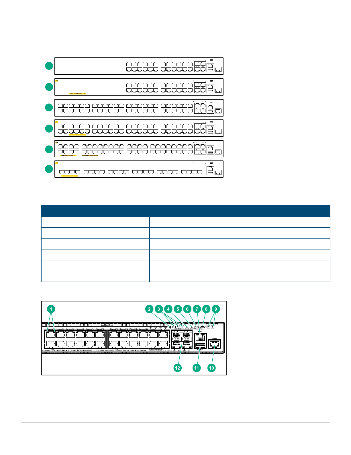
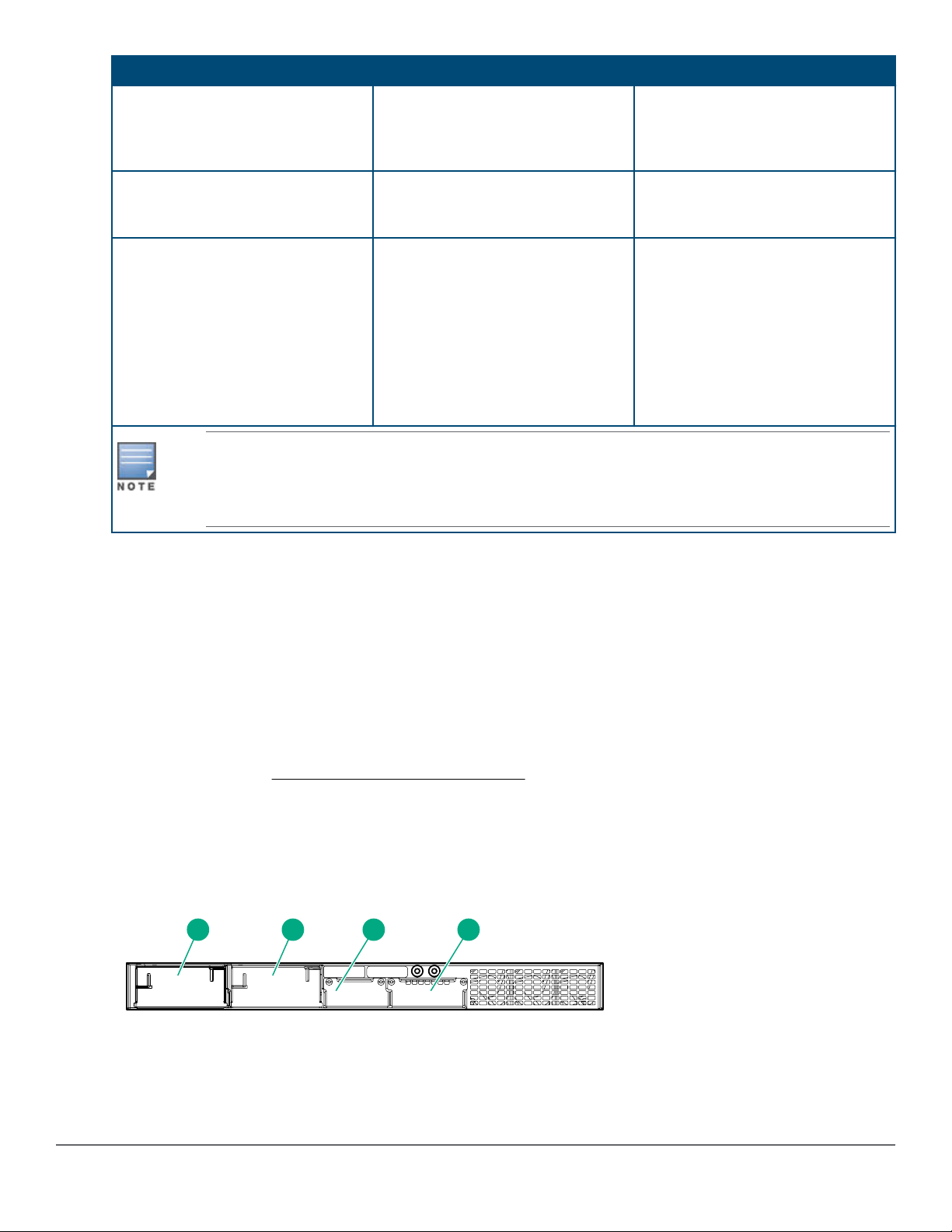
Front of the switches
1
2
3
4
5
6
Figure 1: Front of all the 2930M switches
Table 1: Front of all the 2930M switches: Label and description
Label Description
1 Aruba 2930M 24G 1-slot switch (JL319A)
2 Aruba 2930M 24G PoE+ 1-slot switch (JL320A)
3 Aruba 2930M 48G 1-slot switch (JL321A)
4 Aruba 2930M 48G PoE+ 1-slot switch (JL322A)
5 Aruba 2930M 40G 8SR PoE+ 1-slot Switch (JL323A)
6 Aruba 2930M 24SR PoE+ 1-slot Switch (JL324A)
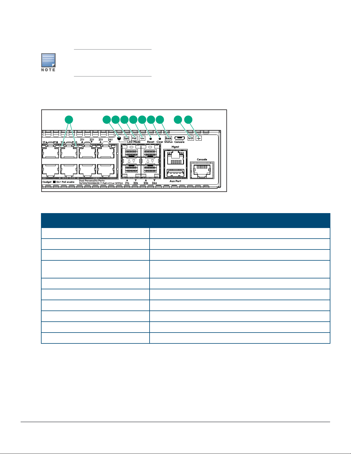
Figure 2: Example of 2930M switch
8 Aruba 2930M Switches
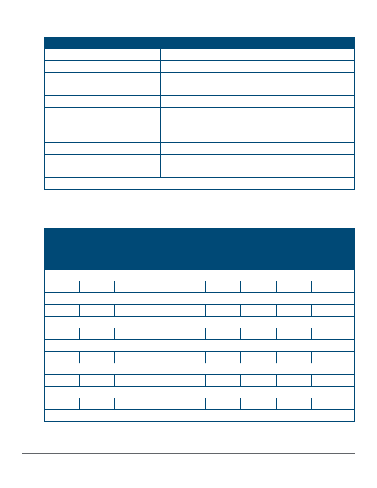
Table 2: 2930M switches: Labels and description
Label Description
1 Switch Port LEDs
2 LED Mode button
3 Speed, PoE*, Usr LEDs
4, 5 Reset, Clear buttons
6 Back Module status LED
7 Out-of-Band Management port
8 Micro USB console
9 Unit Identification, Global Status LEDs
10 RJ serial console
11 USB/auxiliary port
12 Dual-personality SFP ports
* PoE Mode LED is present only on switch models that support PoE.
Network ports
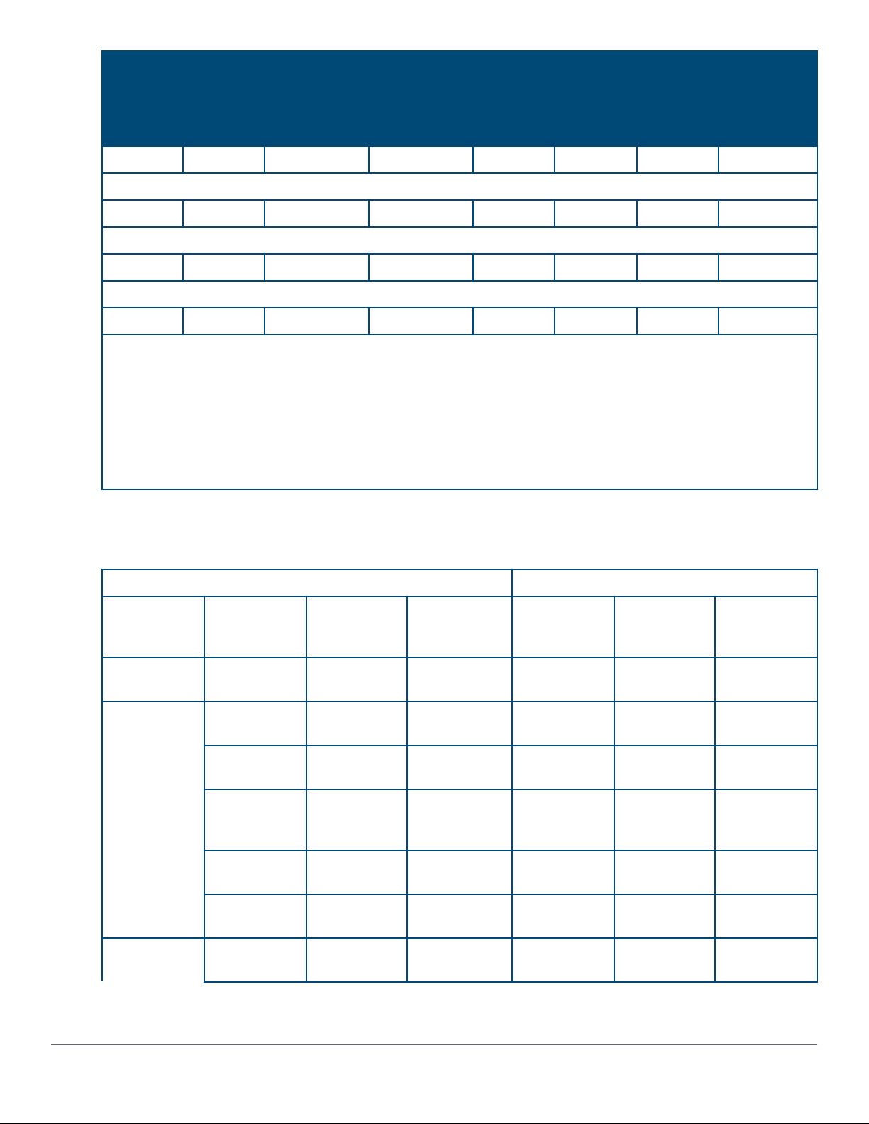
Table 3: Network ports
10/100/100
0 non-PoE
RJ-45
ports
Aruba 2930M 24G 1-slot switch (JL319A):
20
Aruba 2930M 24G PoE+ 1-slot switch (JL320A):
- 20
Aruba 2930M 48G 1-slot switch (JL321A):
44
Aruba 2930M 48G PoE+ 1-slot switch (JL322A):
- 44
Aruba 2930M 40G 8SR PoE+ 1-slot switch (JL323A):
- 36 - 4 - 8
Aruba 2930M 24SR PoE+ 1-slot switch (JL324A):
- - - - - 24
1
1
10/100/100
0 PoE/PoE
+ RJ-45
ports
Combo
10/100/1000B
aseT-100/100
0Gbps SFP
ports
Combo/
10/100/1000B
aseT PoE+ -
100/1000Gbp
s SFP ports
SFP+
ports
- 4 - - - - -
1
- 4 - - - -
- 4 - - - - -
1
- 4 - - - -
Smart
Rate
PoE/PoE+
3
4
40G Stacking
ports
- -
- -
Aruba 2930 2-port stacking module (JL325A):
Table Continued
Chapter 1 Introducing the 2930M switches 9
10/100/100
0 non-PoE
RJ-45
ports
10/100/100
0 PoE/PoE
+ RJ-45
ports
Combo
10/100/1000B
aseT-100/100
0Gbps SFP
ports
Combo/
10/100/1000B
aseT PoE+ -
100/1000Gbp
s SFP ports
SFP+
ports
Smart
Rate
PoE/PoE+
40G Stacking
ports
- - - - - - - 2
Aruba 3810M/2930M 1 Port QSFP+ 40GbE module (JL078A):
- - - - - - 1 -
Aruba 3810M/2930M 4 HPE Smart Rate 1G/2.5G/5G/10G PoE+ module (JL081A):
- - - - - 4 - -
Aruba 3810M/2930M 4 Port 100M/1G/10G SFP+ MACsec module (JL083A):
- - - - 4
2
- - -
Notes:
1
All RJ-45 ports support “Auto-MDIX”, which means you can use either straight-through or crossover twisted-
pair cables to connect network devices to the switch.
2
SFP+ ports support 100Mb (100-FX and 100-BX), 1G SFP and 10G SFP+ transceivers.
3
JL323A Smart Rate ports are 1G/2.5G/5G/10G.
4
JL324A Smart Rate ports are 1G/2.5G/5G (no 10G support).
These products also support optional network connectivity:
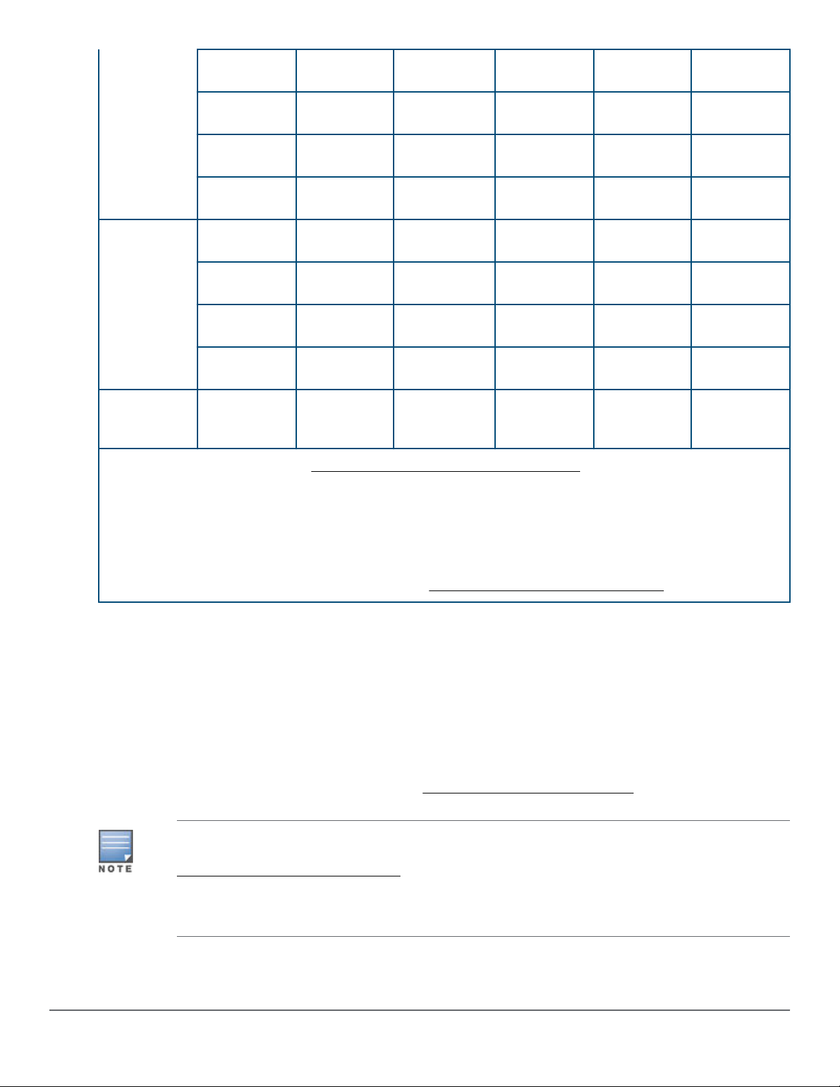
Table 4: Optional network connectivity, speeds, and technologies
Transceiver Form-Factor and Connector
Speed Technology Cabling Uplink
Module
Connector
100 Mbps 100-FX Fiber
(multimode)
1 Gbps 1000-T Copper
(twisted-pair)
1000-SX Fiber
(multimode)
1000-LX Fiber
(multimode or
single mode)
1000-LH Fiber (single
mode)
1000-BX Fiber (single
mode)
- LC - -
- RJ-45 - -
- LC - -
- LC - -
- LC - -
- LC - -
SFP ("mini-
GBIC")
Connector
SFP+
Connector
1
QSFP+
Connector
10 Gbps 10-Gig Direct
Attach
Copper
(twinaxial)
- - Not
Applicable
-
Table Continued
10 Aruba 2930M Switches
10-Gig SR Fiber
(multimode)
- - LC -
10-Gig LRM Fiber
(multimode)
10-Gig LR Fiber (single
mode)
10-Gig ER Fiber (single
mode)
40 Gbps 40-Gig Direct
Attach 1/3/5 m
40-Gig SR4 Fiber
40-Gig ESR4 Fiber
40-Gig LR4 Fiber (single
Smart Rate
1/2.5/5/10
Gbps
1
For supported transceivers, visit http://www.hpe.com/networking/support .
• In the first textbox, type J4858 (for 100-Mb and Gigabit information), J8436 (for 10-Gigabit information), or
JH231 (for 40–Gigabit information).
• Select any of the products that display in the dropdown list.
• Select Support Center. Then click on Manuals, followed by View All to and find the Transceiver Support
Matrix.
Smart Rate Copper
Copper
(twinaxial)
(multimode)
(multimode)
mode)
(twisted pair)
- - LC -
- - LC -
- - - -
- - - Not Applicable
- - - MPO
- - - MPO
- - LC LC
RJ-45 - - -
For technical details of cabling and technologies, see Cabling and technology information.
Management ports
Console Ports
There are two serial console port options on the switch: an RJ-45 or Micro USB. These ports are used to connect
a console to the switch either by using an Aruba X2C2 RJ45 to DB9 Console Cable (JL448A) (sold separately) or
a standard Micro USB cable (not supplied). The Micro USB connector has precedence for input. If both cables are
plugged in, the console output is echoed to both the RJ-45 and the Micro-USB ports, but the input is only
accepted from the Micro-USB port.
For more information on the console connection, see Setting up a console connection. The console can be a
PC or workstation running a VT-100 terminal emulator, or a VT-100 terminal.
USB Console Port driver download: When using the Micro USB Console Port, the connected PC
first requires “virtual COM port” USB drivers to be installed. USB console drivers are available at
www.hpe.com/networking/support. Type a product name (for example, 2930M) or product number
in the Auto Search textbox. Select one of the switches from the drop-down list. Click the Display
selected button. From the options that appear, select Software downloads (on the right side of the
window). Download USB Console Port Drivers and Information.
Chapter 1 Introducing the 2930M switches 11
Auxiliary (Aux) port
21 3 4 5 6 7 8 9 10
An auxiliary port for processing a USB command file or downloading switch software code. This port uses a USB
Type A connector, but does not comply with all USB protocols and standards.
FAT32 USB format is required.
Switch and port LEDs on front of the switches
Figure 3: Switch and port LEDs
Table 5: Switch and port LEDs: Labels and description
Label
1 Port LEDs
2 LED Mode button
3 Speed mode selected LED
4 PoE mode selected LED (only on Aruba 2930M models that support
5 Usr mode selected LED
6 Reset button
7 Clear button
8 Usr LED back status LED
9 UID (Unit Identification)
10 Global status LED
Description
PoE+ operation)
12 Aruba 2930M Switches

Table 6: Front of switch status and mode LED behavior
Switch LEDs Function State Meaning
Global Status Internal Power Status of
the switch. Self-Test
Status Switch/Port Fault
Status
On Green The Switch has passed self-
test and is powered up
normally.
Slow Flash Green* The switch self-test and
initialization are in progress
after the switch has been
power cycled or reset. The
switch is not operational until
this LED stops blinking green.
Slow Flash Orange* A fault or self-test failure has
occurred on the switch, one of
the switch ports, or a module
in the rear of the switch. The
Status LED for the
component with the fault will
blink simultaneously.
On Orange If this LED is on orange for a
prolonged time, the switch
has encountered a fatal
hardware failure, or has failed
its self-test.
Off The unit is not receiving
power.
UID (Unit Identification) The Unit Identification
LED is used to help you
to identify a particular
unit in a rack or
collection of products.
Out-of-Band Management
(OOBM) Port LED: Activity/
Link
Display Activity/Link and
port status of OOBM
On or Fast Flash** The “chassislocate” command
allows you to blink or turn on
the LED for a specified
number of minutes (1-1440).
The default is 30 minutes.
Off LED will turn off after the
timeout period has expired.
Half-Bright Green The port is enabled and
receiving a Link indication
from the connected device.
On Green The port is experiencing high
bandwidth utilization.
Table Continued
Chapter 1 Introducing the 2930M switches 13

Switch LEDs Function State Meaning
Activity Flicker Green The percentage of time that
the LED is full-bright is
roughly proportional to the
percentage of full bandwidth
utilization of the port. Even
just one packet will trigger a
visible full-bright flicker. HalfBright Green port Link
indication remains on as
Activity flickers from halfbright to full-bright.
Slow Flash Orange The port has failed its self-
test. Flashes simultaneously
with the Global Status LED
flashing orange.
Off The port is disabled, not
connected, or not receiving
link.
Back Module Status Status of modular
components installed in
the back of the unit.
Speed Mode Selected Indicates when the Port
LEDs are showing port
speed information.
Power over Ethernet (PoE)
Mode Selected***
Indicates when the Port
LEDs are showing PoE
status information.
On Green Normal operation: All modular
components installed in the
back of the unit are
functioning correctly.
Slow Flash Orange* One of the modules inserted
from the back of the chassis
(power supply or stacking
module) has failed self test or
is experiencing a fault
condition. Flashes
simultaneously with the
Global Status LED flashing
orange.
Off No modular components
installed in the back of the
chassis.
On Speed Mode is selected. Port
LEDs indicate port speed.
Off Speed mode not selected.
On Green PoE Mode is selected. Port
LEDs show PoE information.
On Orange PoE Mode is selected and a
port also has a PoE error. The
Global Status LED and the
LED corresponding to the port
with the error will be flashing
orange. The rest of the Port
LEDs will display normal PoE
status.
Table Continued
14 Aruba 2930M Switches
Switch LEDs Function State Meaning
Slow Flash Orange* PoE Mode has NOT been
selected and a port has a
PoE error. LED will be
flashing orange
simultaneously with the
Global Status LED and the
LED corresponding to the port
with the error. The rest of the
Port LEDs will display normal
PoE status.
Off PoE mode is not selected.
User Mode Selected When stacking is
enabled, the Port LEDs
are displaying stack
information and status.
When stacking is
disabled, this mode is
reserved for future use.
Save Power Mode
Selected
* The slow blink behavior is an on/off cycle once every 1.6 seconds, approximately.
** The fast blink behavior is an on/off cycle once every 0.5 seconds, approximately.
*** Applies only to switches that support PoE/PoE+.
On Green User Mode is selected.
Off User mode not selected.
This mode is indicated by ALL the switch indicator LEDs
being off, except for the Global Status LED. This display
occurs only if the switch has been configured with the
savepower led command. See the Management and
Configuration Guide for more information on that
command.
Table 7: Port LEDs and mode behavior
Switch LEDs Function State/Mode Meaning
Port LEDs To display the information
for the port as selected by
the LED Mode select
button. When transceivers
and SFPs are installed,
this LED is also used to
indicate that the
installation has occurred
by turning on for two
seconds then off.
Activity/Link Shows port Activity and
Link status. This is the
DEFAULT. There is no
dedicated mode LED
indicating this mode. The
Mode LED function should
return to this selection 10
minutes after the last
press of the LED Mode
button.
Speed Shows port speed
configuration.
PoE Shows PoE information.
User Shows user-selectable
behavior.
Table Continued
Chapter 1 Introducing the 2930M switches 15

Switch LEDs Function State/Mode Meaning
Activity/Link Mode
Selected
Port LEDs are displaying
Link status and network
activity information
simultaneously. Activity/
Link Mode is the default
mode and is in effect
unless another LED mode
has been selected.
Half-Bright Green The port is enabled and
receiving a Link indication
from the connected
device.
Activity Flicker Green The percentage of time
that the LED is full-bright
is roughly proportional to
the percentage of full
bandwidth utilization of the
port. Half-Bright Green
port Link indication
remains on as Activity
flickers from half-bright to
full-bright.
Slow Flash Orange* The corresponding port
has failed its self-test.
Flashes simultaneously
with the Global Status
LED flashing orange.
Off The Port is disabled, not
connected, or not
receiving link.
Speed Mode Selected Port LEDs are displaying
the connection speed at
which each port is
operating.
PoE Mode Selected Port LEDs are displaying
PoE information.
Fast Flash Green** The port is operating at 40
Gbps.
On Green The port is operating at 10
Gbps.
Triple Blink Green The port is operating at 5
Gbps. (HPE Smart Rate
ports only)
Double Blink Green The port is operating at
2.5 Gbps. (HPE Smart
Rate ports only)
Slow Flash Green* The port is operating at 1
Gbps.
Off The port is not Linked, or
is operating at 10 or 100
Mbps.
On Green The port is providing PoE
power.
On Orange PoE is disabled on the
port.
Fast Flash Orange** The port is denied power
or is detecting an external
PD fault.
Table Continued
16 Aruba 2930M Switches

Switch LEDs Function State/Mode Meaning
Slow Flash Orange* The port has an internal
hardware failure. Flashes
simultaneously with the
Global Status LED
flashing orange.
Off The port is not providing
PoE power.
User Mode Selected
Mode currently active only
in stacked configurations.
Used to display the
number of members in a
stack and their current
status.
The status information is
sticky and if a unit’s status
changes while in USER
mode, you must exit and
re-enter USER mode to
get the updated status.
On Green Stack Member exists in
the stack and is
operational.
Slow Flash Green* Indicates the Member # of
the chassis.
Fast Flash Green** Indicates the Member # of
the Commander of the
stack.
On Orange Stack Member is currently
booting or has a fault that
is preventing it from
communicating.
Slow Flash Orange*
Fast Flash Orange**
Stack Member is in a
known fault condition (for
example, a PSU fault).
The Global Status LED on
all stack members will also
Slow Flash Orange.
Stack Member is in a Alert
condition (i.e. Overtemp,
PoE Over subscript, etc.).
The Global Status LEDs
on all stack members will
remain in normal
operational.
Off Stack Member does not
exist in the stack
configuration.
* The slow blink behavior is an on/off cycle once every 1.6 seconds, approximately.
** The fast blink behavior is an on/off cycle once every 0.5 seconds, approximately.
*** Applies only to switches that support PoE/PoE+.
Example of USER mode behavior
Assume you have a 4-member stack, in a ring topology, with member numbers 1, 2, 3 and 5. Member 1 is the
commander and member 3 is rebooting. In USER mode, the members will show the following on their port LEDs:
Chapter 1 Introducing the 2930M switches 17
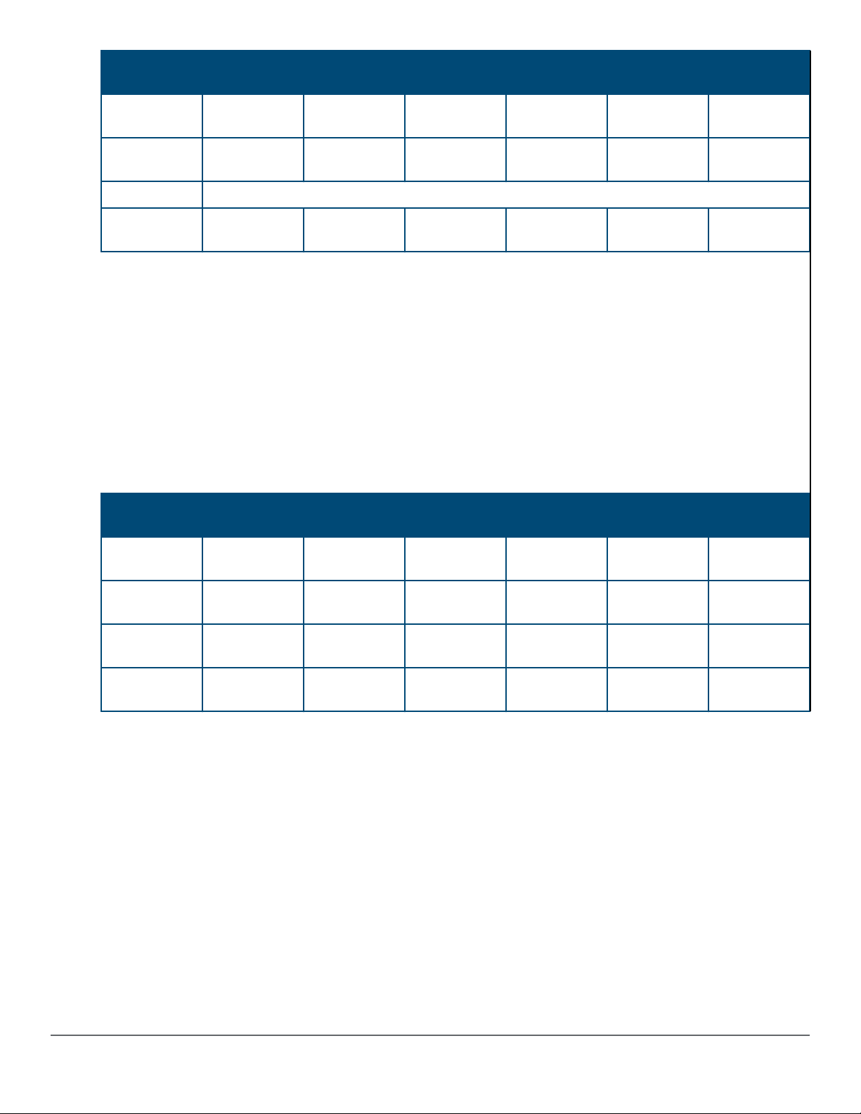
Port 1 LED Port 2 LED Port 3 LED Port 4 LED Port 5 LED Port 6-10
LEDs
Member 1 Fast Flash
Green
Member 2 Fast Flash
Green
Member 3 Going through normal boot up sequencing
Member 5 Fast Flash
Green
Looking at any member, you can see that there are 4 members defined in the stack configuration, with member
numbers 1, 2, 3, and 5 because these are the LEDs that are lit. The port 4 LED is off, indicating that this member
number is not defined in the stack.
On all members, Port 1 LED is fast flashing, indicating that member 1 is the commander of the stack. Port 3 LED
is on orange, indicating either that 3 is rebooting or not communicating because of an unknown fault.
When looking at member 1, only Port 1 LED is fast flashing green. This indicates that this unit is member 1 and is
the commander.
When looking at member 2, the port 2 LED is slow flashing green, indicating that unit is member number 2.
Likewise on member 5, the port 5 LED is slow flashing green, indicating that unit is member 5.
Member 3 will be going through the normal boot LED boot up sequence. When it has completed booting and
joined the stack, if you exit and re-enter USER mode, the members show the following on their port LEDs:
Port 1 LED Port 2 LED Port 3 LED Port 4 LED Port 5 LED Port 6-10
On Green On Orange Off On Green Off
Slow Flash
Green
On Green On Orange Off Slow Flash
On Orange Off On Green Off
Off
Green
LEDs
Member 1 Fast Flash
Green
Member 2 Fast Flash
Green
Member 3 Fast Flash
Green
Member 5 Fast Flash
Green
On Green On Green Off On Green Off
Slow Flash
Green
On Green Slow Flash
On Green On Green Off Slow Flash
On Green Off On Green Off
Off On Green Off
Green
Off
Green
LED mode select button and indicator LEDs
The state of the mode LEDs is controlled by the LED Mode select button. The current view mode is indicated by
the mode LEDs next to the button. Press the button to step from one view mode to the next.
18 Aruba 2930M Switches
Stacking Notes
• For 2930M switches that are in a stack, the LED Mode select button on every switch in the stack
controls the LED mode for all the switches in the stack. Using the LED Mode select button on one
switch in the stack changes the LED mode for the entire stack.
• If there is a combination of PoE/PoE+ switches and non-PoE switches in the stack, when any of
the LED Mode select buttons is pressed to put the stack into PoE mode, the non-PoE switches
indicate no PoE support by not illuminating any of the mode indicator LEDs or any of the port
LEDs.
• If any of the switches in the stack are configured with the Save Power LED feature, the default
LED mode for the whole stack becomes the Save Power display (all LED mode indicator LEDs
are off), but only the stack members on which that feature is configured display the other
characteristics of that feature (all LEDs off except for the power LED).
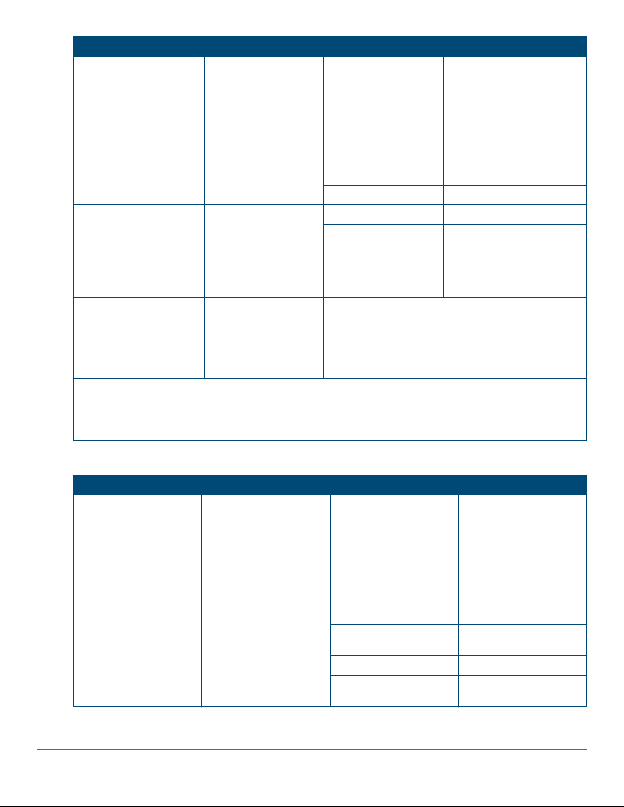
Reset and Clear buttons
The Reset and Clear buttons are recessed from the front panel (to protect them from being pushed accidentally)
and are accessible through small holes on the top of the front panel. Use pointed objects, such as unbent paper
clips, to push them.
The buttons are used singly or in combination, as follows:
To accomplish this: Do this: This will happen:
Soft reset (Standalone switch) Press and release the Reset button The switch operating system is
cleared gracefully (such as data
transfer completion, temporary error
conditions are cleared), then
reboots and runs self-tests.
Hard reset (Standalone switch) Press and hold the Reset button for
more than 5 seconds (until all LEDs
turn on), then release.
Soft reset (Stacked switch) Press and release the Reset button Same as a standalone switch,
Hard reset (Stacked switch) Press and hold the Reset button for
more than 5 seconds (until all LEDs
turn on), then release.
The switch reboots, similar to a
power cycle. A hard reset is used,
for example, when the switch CPU
is in an unknown state or not
responding.
except:
• If action happened on the
commander, the standby switch
will become commander.
• If action happened on the
standby, a new standby will be
elected.
Same as a standalone switch,
except:
• If action happened on the
commander, the standby switch
will become commander.
• If action happened on the
standby, a new standby will be
elected.
Table Continued
Chapter 1 Introducing the 2930M switches 19
To accomplish this: Do this: This will happen:
1 2 3 4
Delete console and management
access passwords
Turn off UID LED Press Clear button and release
Restore the factory default
configuration
These buttons are provided for your convenience. If you are concerned with switch security, make
sure that the switch is installed in a secure location, such as a locked wiring closet. You can also
disable these buttons by using the front-panel-security command. See the 2930M
Management and Configuration Guide for a description of that command.
Press Clear button for more than 5
seconds, but within 15 seconds (in
btw 5 - 15 seconds)
within 5 seconds (in btw 0.5 - 5
seconds)
1. Press Clear and Reset
simultaneously.
2. While continuing to press Clear,
release Reset.
3. When the Global Status LED
begins to fast flash orange (after
approximately 5 seconds), release
Clear.
Clears all passwords. Will flash
Global Status Green LED, after 5
seconds has expired to indicate
passwords have cleared.
Clears the UID LED.
The switch removes all
configuration changes, restores the
factory default configuration, and
runs self test.
Out-of-band management (OOBM) port
This RJ-45 port is used to connect a dedicated management network to the switch. To use it, connect an RJ-45
network cable to the management port to manage the switch through Telnet from a remote PC or a UNIX
workstation.
To use this port, the switch must have an IP address. IP settings can be configured through a console port
connection or automatically from a DHCP/Bootp server.
A networked out-of-band connection through the management port allows you to manage data network switches
from a physically and logically separate management network.
For more information, see the Network Out-of-Band Management (OOBM) appendix in the Management and
Configuration Guide at www.hpe.com/networking/support.
Back of the switches
The back of all 2930M switches is the same.
Figure 4: Back of the 2930M switches
20 Aruba 2930M Switches

Table 8: Back of the 2930M switches: Label and description
Label Description
1 AC power connector / power supply slot 1
2 AC power connector / power supply slot 2
3 Stacking module slot
4 Uplink module slot
Power supplies
The following power supplies can be installed in the 2930M switches:
• Aruba X371 12VDC 250W 100-240VAC Power Supply (JL085A): A 250 watt power supply for the non-PoE
switches. This power supply does not provide any PoE power, and is keyed so that it will not fit into the power
supply slots of 2930M PoE+ switches.
• Aruba X372 54VDC 680W 100-240VAC Power Supply (JL086A): A 680 watt power supply for 2930M PoE+
supported switches. This power supply offers up to 370 watts of PoE+ power, and is keyed so that it does not
fit into the power supply slots of non-PoE+ 2930M switches.
• Aruba X372 54VDC 1050W 110-240VAC Power Supply (JL087A): A 1050 watt power supply for 2930M PoE
+ supported switches. This power supply offers up to 740 watts of PoE+ power, and is keyed so that it does
not fit into the power supply slots of non-PoE+ 2930M switches.
For initial power supply installation, refer to the Aruba 3810M/2930M Switch Power Supply Quick Setup Guide
and Safety/Regulatory Information that was shipped with the power supply units.
For more power supply information, see (Optional) Installing a second power supply.
Power connector
The 2930M switches do not have a power switch. They will power on when either one or both power supplies are
connected to an active AC power source.
Stacking module slot
Each of the 2930M switches has one module slot that can accept the following:
• 2930M Stacking Module (JL325A)
• 2920/2930M 0.5m Stacking Cable (J9734A)
• 2920/2930M 1.0m Stacking Cable (J9735A)
• 2920/2930M 3.0m Stacking Cable (J9736A)
These components provide high-speed connectivity to other 2930M switches. Only the 2930M switches support
this module.
Uplink port slot and module support
The 2930M family of switches features a module slot that allows the user to customize the uplink ports on the
switch. The slot support 40Gbps of maximum bandwidth and is available in three possible options: 4 Smart Rate,
4 SFP+, or 1 QSFP+.
Unsupported modules are mechanically prevented from installing into unsupported slots.
Chapter 1 Introducing the 2930M switches 21
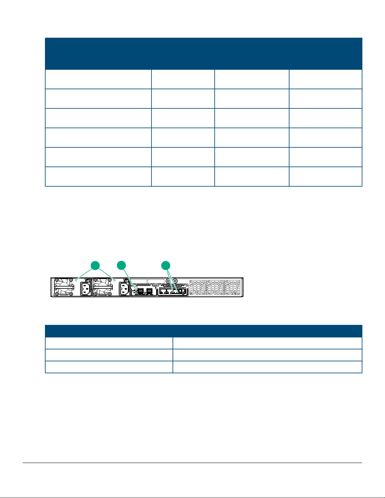
Table 9: Switch module/support matrix
1 3
2
Module support
Switch model JL078A 1QSFP+ JL081A Smart Rate 1G/
JL319A Aruba 2930M 24G 1-slot
switch
JL320A Aruba 2930M 24G PoE+ 1slot switch
JL321A Aruba 2930M 48G 1-slot
switch
JL322A Aruba 2930M 48G PoE+ 1slot switch
JL323A Aruba 2930M 40G 8SR
PoE+ 1-slot Switch
JL324A Aruba 2930M 24SR PoE
+ 1-slot Switch
2.5G/5G/10G PoE+
Yes Yes, but no PoE Yes
Yes Yes Yes
Yes Yes, but no PoE Yes
Yes Yes Yes
Yes Yes Yes
Yes Yes Yes
JL083A 4SFP+
LEDs on the back of the switches
This section describes the LEDs on the back of the switch. When the back LED on the front of the unit is blinking
a fault, the user can look at the back of the switch to find the corresponding blinking LED for the faulted module or
power supply. If a user installs a second power supply and did not turn on the power (PSU module status = OFF),
the back LED will blink orange.
Figure 5: LEDs on the back of switches
Table 10: Back of the 2930M switches LED labels and description
Label Description
1 Power supply unit (PSU) status LED
2 Stacking module status LED
3 Uplink module status LED
22 Aruba 2930M Switches
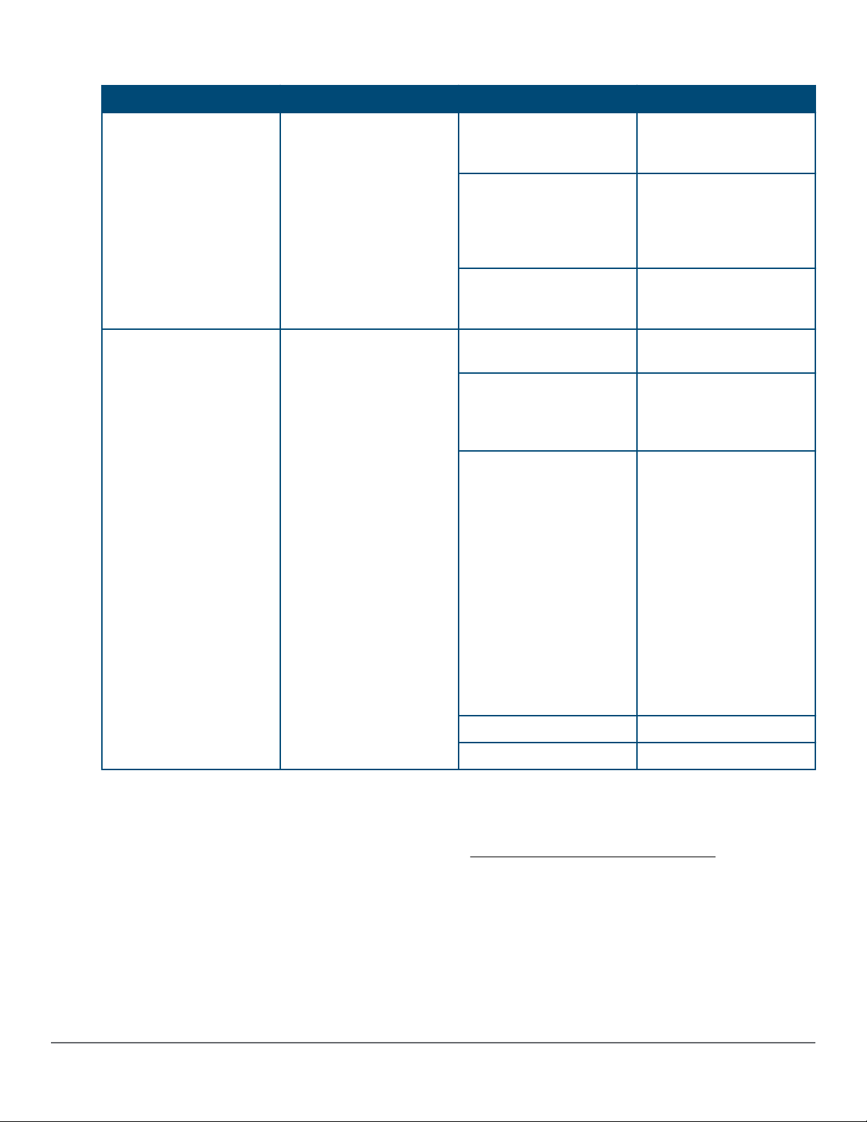
Table 11: LEDs on the back of the switch
Switch LEDs Function State Meaning
PSU module Status Status of PSU: Looking at
the back of the unit, PSU1
is on the left and PSU2 is
on the right.
Uplink module status Status of uplink module On Green Uplink module operating
On Green The power supply has
valid AC input and valid
DC outputs.
Slow Flash Green Either the power supply
has an internal fault, or
switch has a fault that is
causing power supply to
cycle on/off.
Off The power supply has an
invalid AC input, or invalid
DC outputs.
correctly.
Slow Flash Orange* Uplink module has
experienced a fault. The
Global Status LED should
be flashing synchronously.
Fast Flash Orange**
Uplink module or one or
more of its ports is/are
experiencing an alert
condition.
Alert conditions include
that an unsupported cable
has been installed in the
module or that the uplink
module has been installed
while the switch was
powered on (hot-swapped)
and the switch needs to be
rebooted to support the
module.
Off No power
No Present No Module
2930M stacking module
The 2930M 2-port stacking module (JL325A) is a component you can add to an 2930M switch to provide highspeed stacking connections to other 2930M switches. See Stacking information and topologies and the HPE
Chapter 1 Introducing the 2930M switches 23
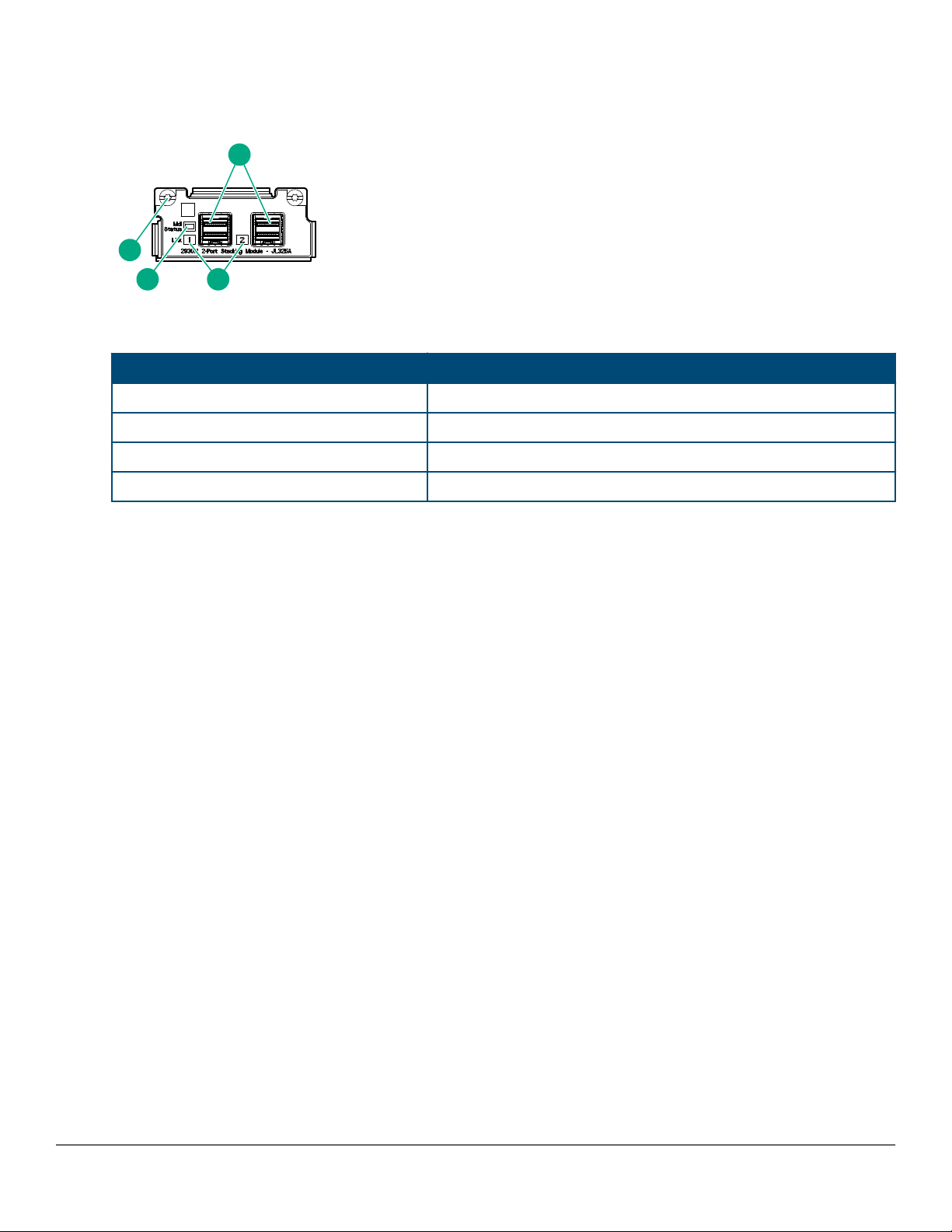
ArubaOS-Switch Advanced Traffic Management Guide for your switch OS version for more information about
1
23
4
stacking configuration and operation.
Figure 6: Front of 2930M 2-port stacking module
Table 12: Front of 2930M 2-port stacking module: Label and description
Label Description
1 Stacking connectors
2 Link LEDs
3 Stacking module status LED
4 Module retaining screws
The 2930M 2-port stacking module JL325A has the following features:
• Two stacking connectors for connecting the 2930M switch to other 2930Ms in a stacked topology (ring only).
Any of these available stacking cables can be used for these connections:
◦ Aruba 2920/2930M 0.5M Stacking Cable (J9734A)
◦ Aruba 2920/2930M 1.0m Stacking Cable (J9735A)
◦ Aruba 2920/2930M 1.0m Stacking Cable (J9735A)
• LEDs, described below.
Stacking module LEDs
The following LEDs are located on the 2930M stacking module itself and are only viewable from the rear of the
switch.
24 Aruba 2930M Switches

Table 13: Stacking module LEDs
Name Function Mode Description
Stacking Module Status Status of Stacking module On Green Stacking module operating
correctly.
Slow Flash Orange Stacking module has
experienced a fault, or one
or more of the module
ports has experienced a
fault. The 1.6 seconds
cycle flash should be
synchronized with the
switch Global Status LED.
The Global Status and
Back LED should also be
flashing.
Stacking Link Status The Link LED per stacking
port indicates the port is
enabled, connected and
detects a signal from the
attached device.
Fast Flash Orange
Off No power
On Green The port is enabled and
Slow Flash Orange Port Failed POST or cable
Stacking module or one or
more of its ports is
experiencing an alert
condition.
Alert conditions include
that an unsupported cable
has been installed in the
module or that the
stacking module has been
installed while the switch
was powered on (hotswapped) and the switch
needs to be rebooted to
support the module.
The BACK LED should be
flashing and the Global
Status LED should NOT
be flashing.
receiving a link indication
from the connected
device.
fault. Module Status LED
on the stacking module
and Global Status and
Back LED on front of unit
should also be
synchronized and flashing
orange.
Off No cable plugged in
Chapter 1 Introducing the 2930M switches 25
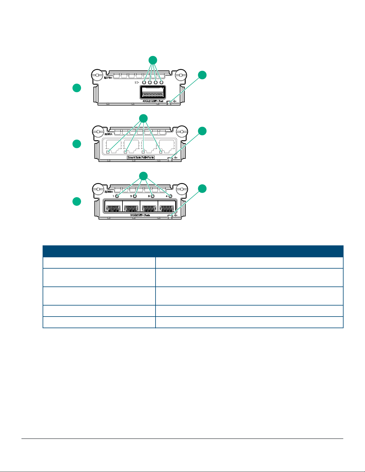
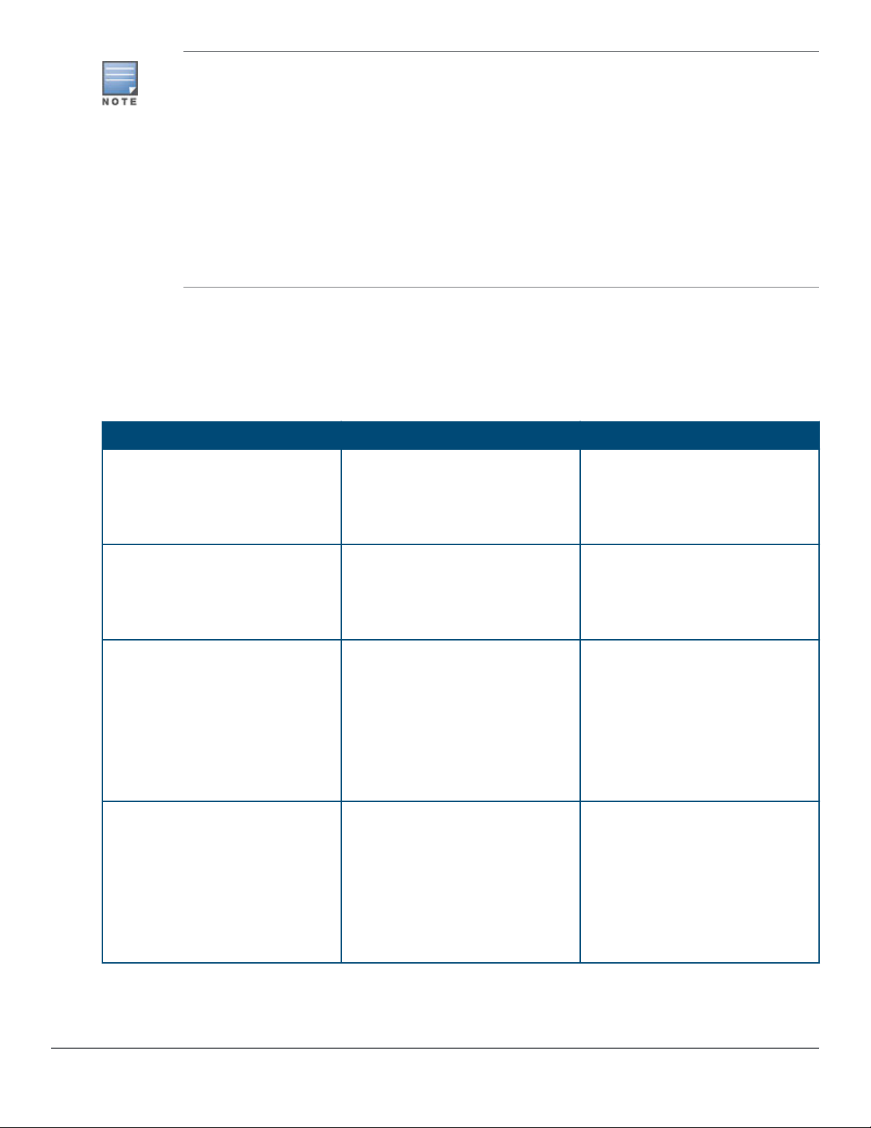
2930M uplink modules
1
4
2
5
5
4
3
5
4
Figure 7: Front of 2930M uplink modules
Table 14: 2930M uplink modules: Label and description
Label Description
1 Aruba 3810M/2930M 1-port QSFP+ 40GbE Module (JL078A)
2 Aruba 3810M/2930M 4 HPE Smart Rate 1G/2.5G/5G/10G PoE+
Module (JL081A)
3 Aruba 3810M/2930M 4-port 100M/1G/10G SFP+ MACsec Module
(JL083A)
4 Port LEDs
5 Uplink module status LED
Uplink module LEDs
Each QSFP+ port has four green/orange bi-color LEDs to communicate port-level information. The four LEDs are
located above each QSFP+ port as shown below.
26 Aruba 2930M Switches
Loading...