


 Loading...
Maintenance and Service Guide
HP ProBook 445 G7 Notebook PC
IMPORTANT! This document is intended for HP authorized service providers only.
© Copyright 2020 HP Development Company,
L.P.
AMD, Radeon, and Ryzen are trademarks of Advanced Micro Devices, Inc. Bluetooth is a trademark owned by its proprietor and used by HP Inc. under license. Intel and Thunderbolt are trademarks of Intel Corporation in the U.S. and other countries. SDHC, SDXC, and microSD are trademarks or registered trademarks of SD-3C in the United States, other countries or both. Microsoft and Windows are either registered trademarks or trademarks of Microsoft Corporation in the United States and/or other countries. DisplayPort™ and the DisplayPort™ logo are trademarks owned by the Video Electronics Standards Association (VESA®) in the United States and other countries.
The information contained herein is subject to change without notice. The only warranties for HP products and services are set forth in the express warranty statements accompanying such products and services. Nothing herein should be construed as constituting an additional warranty. HP shall not be liable for technical or editorial errors or omissions contained herein.
First Edition: April 2020
Document Part Number: L92357-001
Product notice
This guide describes features that are common to most models. Some features may not be available on your computer.
Not all features are available in all editions or versions of Windows. Systems may require upgraded and/or separately purchased hardware, drivers, software or BIOS update to take full advantage of Windows functionality. Windows 10 is automatically updated, which is always enabled. ISP fees may apply and additional requirements may apply over time for updates. Go to http://www.microsoft.com for details.
To access the latest user guides, go to http://www.hp.com/support, and follow the instructions to nd your product. Then select
User Guides.
Software terms
By installing, copying, downloading, or otherwise using any software product preinstalled on this computer, you agree to be bound by the terms of the HP End User License Agreement (EULA). If you do not accept these license terms, your sole remedy is to return the entire unused product (hardware and software) within 14 days for a full refund subject to the refund policy of your seller.
For any further information or to request a full refund of the price of the computer, please contact your seller.

Safety warning notice
 WARNING! To reduce the possibility of heat-related injuries or of overheating the computer, do not place the computer directly on your lap or obstruct the computer air vents. Use the computer only on a hard, flat surface. Do not allow another hard surface, such as an adjoining optional printer, or a soft surface, such as pillows or rugs or clothing, to block airflow. Also, do not allow the AC adapter to contact the skin or a soft surface, such as pillows or rugs or clothing, during operation. The computer and the AC adapter comply with the user-accessible surface temperature limits de ned by applicable safety standards.
iii
iv Safety warning notice

Table of contents
1 Product description ....................................................................................................................................... |
1 |
2 Components .................................................................................................................................................. |
6 |
Right ....................................................................................................................................................................... |
6 |
Left ......................................................................................................................................................................... |
8 |
Display .................................................................................................................................................................... |
9 |
Keyboard area ...................................................................................................................................................... |
10 |
Touchpad ........................................................................................................................................... |
10 |
Lights ................................................................................................................................................. |
11 |
Button, speakers, and ngerprint sensor ......................................................................................... |
12 |
Special keys ....................................................................................................................................... |
13 |
Bottom ................................................................................................................................................................. |
14 |
Labels ................................................................................................................................................................... |
15 |
3 Illustrated parts catalog .............................................................................................................................. |
16 |
Computer major components .............................................................................................................................. |
16 |
Display components ............................................................................................................................................ |
19 |
Cable Kit ............................................................................................................................................................... |
20 |
Bracket Kit ............................................................................................................................................................ |
21 |
Mass storage devices ........................................................................................................................................... |
22 |
Miscellaneous parts ............................................................................................................................................. |
23 |
4 Removal and replacement procedures preliminary requirements .................................................................... |
26 |
Tools required ...................................................................................................................................................... |
26 |
Service considerations ......................................................................................................................................... |
26 |
Plastic parts ....................................................................................................................................... |
26 |
Cables and connectors ...................................................................................................................... |
26 |
Drive handling ................................................................................................................................... |
27 |
Workstation guidelines ..................................................................................................................... |
27 |
Electrostatic discharge information .................................................................................................................... |
27 |
Generating static electricity .............................................................................................................. |
28 |
Preventing electrostatic damage to equipment ............................................................................... |
28 |
Personal grounding methods and equipment .................................................................................. |
29 |
Grounding the work area ................................................................................................................... |
29 |
Recommended materials and equipment ........................................................................................ |
29 |
Packaging and transporting guidelines .............................................................................................................. |
30 |
v
5 Removal and replacement procedures for authorized service provider parts .................................................... |
31 |
Component replacement procedures .................................................................................................................. |
31 |
Preparation for disassembly ............................................................................................................. |
31 |
Battery Safe mode ............................................................................................................................ |
31 |
Bottom cover ..................................................................................................................................... |
32 |
Battery ............................................................................................................................................... |
33 |
Memory modules ............................................................................................................................... |
34 |
WLAN/Bluetooth combo card ............................................................................................................ |
35 |
M.2 solid-state drive ......................................................................................................................... |
37 |
Hard drive .......................................................................................................................................... |
38 |
Speaker assembly ............................................................................................................................. |
40 |
Fan ..................................................................................................................................................... |
41 |
Heat sink ............................................................................................................................................ |
42 |
USB board .......................................................................................................................................... |
44 |
Touchpad assembly ........................................................................................................................... |
45 |
Fingerprint sensor assembly ............................................................................................................ |
46 |
Card reader board .............................................................................................................................. |
48 |
RTC battery ........................................................................................................................................ |
50 |
Power connector cable ...................................................................................................................... |
52 |
System board .................................................................................................................................... |
53 |
Display assembly ............................................................................................................................... |
56 |
Keyboard/top cover ........................................................................................................................... |
65 |
6 Computer Setup (BIOS), TPM, and HP Sure Start ............................................................................................. |
66 |
Using Computer Setup ......................................................................................................................................... |
66 |
Starting Computer Setup .................................................................................................................. |
66 |
Navigating and selecting in Computer Setup ................................................................................... |
66 |
Restoring factory settings in Computer Setup ................................................................................. |
66 |
Updating the BIOS ............................................................................................................................. |
67 |
Determining the BIOS version ......................................................................................... |
67 |
Downloading a BIOS update ........................................................................................... |
67 |
Changing the boot order using the f9 prompt .................................................................................. |
68 |
TPM BIOS settings (select products only) ........................................................................................................... |
68 |
Using HP Sure Start (select products only) ......................................................................................................... |
69 |
7 Using HP PC Hardware Diagnostics ................................................................................................................ |
70 |
Using HP PC Hardware Diagnostics Windows (select products only) ................................................................. |
70 |
Downloading HP PC Hardware Diagnostics Windows ....................................................................... |
70 |
Downloading the latest HP PC Hardware Diagnostics Windows version ....................... |
71 |
Downloading HP Hardware Diagnostics Windows by product name or number |
|
(select products only) ..................................................................................................... |
71 |
vi
Installing HP PC Hardware Diagnostics Windows ............................................................................. |
71 |
Using HP PC Hardware Diagnostics UEFI ............................................................................................................. |
71 |
Starting HP PC Hardware Diagnostics UEFI ....................................................................................... |
72 |
Downloading HP PC Hardware Diagnostics UEFI to a USB flash drive .............................................. |
72 |
Downloading the latest HP PC Hardware Diagnostics UEFI version .............................. |
72 |
Downloading HP PC Hardware Diagnostics UEFI by product name or number |
|
(select products only) ..................................................................................................... |
73 |
Using Remote HP PC Hardware Diagnostics UEFI settings (select products only) ............................................. |
73 |
Downloading Remote HP PC Hardware Diagnostics UEFI ................................................................. |
73 |
Downloading the latest Remote HP PC Hardware Diagnostics UEFI version ................. |
73 |
Downloading Remote HP PC Hardware Diagnostics UEFI by product name or |
|
number ............................................................................................................................ |
73 |
Customizing Remote HP PC Hardware Diagnostics UEFI settings .................................................... |
73 |
8 Backing up, restoring, and recovering ........................................................................................................... |
75 |
Backing up information and creating recovery media ........................................................................................ |
75 |
Using Windows tools ......................................................................................................................... |
75 |
Using the HP Cloud Recovery Download Tool to create recovery media (select products only) ..... |
75 |
Restoring and recovery ........................................................................................................................................ |
76 |
Restoring, resetting, and refreshing using Windows tools .............................................................. |
76 |
Recovering using HP Recovery media ............................................................................................... |
76 |
Changing the computer boot order ................................................................................................... |
76 |
Using HP Sure Recover (select products only) .................................................................................. |
77 |
9 peci c tions .............................................................................................................................................. |
78 |
Computer speci cations ...................................................................................................................................... |
78 |
35.6 cm (14.0 in) display speci cations .............................................................................................................. |
79 |
Hard drive speci cations ..................................................................................................................................... |
79 |
Solid-state drive speci cations ........................................................................................................................... |
80 |
10 Statement of memory volatility .................................................................................................................. |
81 |
Nonvolatile memory usage ................................................................................................................................. |
83 |
Questions and answers ....................................................................................................................................... |
85 |
Using HP Sure Start (select models only) ............................................................................................................ |
86 |
11 Power cord set requirements ...................................................................................................................... |
87 |
Requirements for all countries ............................................................................................................................ |
87 |
Requirements for speci c countries and regions ................................................................................................ |
88 |
12 Recycling .................................................................................................................................................. |
90 |
vii
Index ............................................................................................................................................................. |
91 |
viii

1Product description
Table 1-1 Product components and their descriptions
Category |
Description |
|
|
Product Name |
HP ProBook 445 G7 Notebook PC |
|
|
Processors |
AMD® Ryzen™ Mobile Processor (15 W) |
|
|
|
Ryzen 7 PRO 4750U, 1.7 GHz/4.2 GHz, eight cores, 8 MB L3 cache; 4 MB L2 cache; AMD Radeon™ Graphics |
|
|
|
Ryzen 7 4700U, 2.0 GHz/4.2 GHz, eight cores, 8 MB L3 cache; 4 MB L2 cache; AMD Radeon Graphics |
|
|
|
Ryzen 5 PRO 4650U, 2.1 GHz/4.0 GHz, eight cores, 8 MB L3 cache; 4 MB L2 cache; AMD Radeon Graphics |
|
|
|
Ryzen 5 4500U, 2.375 GHz/4.0 GHz, six cores, 8 MB L3 cache; 3 MB L2 cache; AMD Radeon Graphics |
|
|
|
Ryzen 3 4300U, 2.7 GHz/3.8 GHz, four cores, 4 MB L3 cache; 2 MB L2 cache; AMD Radeon Graphics |
|
|
Graphics |
Supports HD decode, DX12, HDMI 1.4b up to 4 K @ 30 Hz |
|
|
|
AMD Radeon Graphics |
|
|
|
Supports 4 independent displays when on the HP USB-C Dock G4; Max resolution = 4 K @ 30 Hz |
|
(DisplayPort 1) or 4 K @ 30 Hz (DisplayPort 2) |
|
|
|
Supports 4 independent displays when on the HP Thunderbolt™ Dock 120 W G2; Max resolution = 4 K @ 30 |
|
Hz (DisplayPort 1) or 4 K @ 30 Hz (DisplayPort 2) |
|
|
|
Supports 4 independent displays when on the HP USB-C Mini Dock ; Max resolution = 4 K @ 30 Hz (HDMI) or |
|
1920 × 1080 @ 60 Hz (VGA) |
|
|
|
Supports 4 independent displays when on the HP USB-C Universal Dock; Max resolution = 4 K @ 30 Hz |
|
(DisplayPort 1) or 4 K @ 30 Hz (DisplayPort 2) |
|
|
Panel |
35.6 cm (14.0 in), LED backlight, antiglare, nontouch |
|
|
|
High de nition (HD) (1366 × 768), SVA, 45% CG, eDP, slim, 220 nits |
|
|
|
HD, SVA, 45% CG, eDP, slim, 220 nits, with HD camera |
|
|
|
HD, SVA, 45% CG, eDP, slim, 220 nits, with HD + IR camera |
|
|
|
Full high de nition (FHD) (1920 × 1080), UWVA, 45% CG, eDP, slim, 250 nits |
|
|
|
FHD, UWVA, 45% CG, eDP, slim, 250 nits, with HD camera |
|
|
|
FHD, UWVA, 45% CG, eDP, slim, 250 nits, with HD + IR camera |
|
|
|
FHD, UWVA, 72% CG, eDP, slim, 400 nits, with HD camera |
|
|
|
FHD, UWVA, 72% CG, eDP + PSR, flat, 1000 nits, privacy, with HD camera |
|
|
Memory |
Two customer-accessible memory module slots supporting up to 16 GB of RAM |
|
|
|
Supports dual-channel memory |
|
|
|
PC4-3200, DDR4 SODIMMs |
|
|
|
Supports the following con gurations: |
|
|
|
● 32 GB (16 × 2) |
|
|
1

Table 1-1 Product components and their descriptions (continued)
Category |
Description |
|
|
|
|
|
● |
16 GB (16 × 1) or (8 × 2) |
|
|
|
|
● |
12 GB (8 + 4) |
|
|
|
|
● |
8 GB (8 × 1) or (4 × 2) |
|
|
|
|
● |
4 GB (4 × 1) |
|
|
|
Primary storage |
Supports the following SATA, 7 mm, 2.5 inch hard drive: |
|
|
|
|
|
● |
1 TB, 5400 rpm |
|
|
|
|
● |
500 GB, 7200 rpm |
|
|
|
Primary M.2 storage |
Supports the following M.2 2280 solid-state drives: |
|
|
|
|
|
● |
512 GB, PCIe, NVMe, TLC |
|
|
|
|
● |
512 GB, PCIe, NVMe, value |
|
|
|
|
● |
256 GB, PCIe, NVMe, value |
|
|
|
|
● |
256 GB, SATA, TLC |
|
|
|
|
● |
128 GB, SATA, TLC |
|
|
|
Fixed optical drive |
Supports external USB drive via power port |
|
|
|
|
Audio/Visual |
Audio controls |
|
|
|
|
|
Integrated dual-array microphone (select products only) |
|
|
|
|
|
Integrated mono microphone (select products only) |
|
|
|
|
|
Integrated camera (720p HD) (select products only) |
|
|
|
|
|
Integrated camera (720p HD + IR) (select models only) |
|
|
|
|
|
Camera privacy cover |
|
|
|
|
|
Supports WDR (Wide Dynamic Range) |
|
|
|
|
|
Audio-out (headphone)/audio-in (microphone) combo jack |
|
|
|
|
RJ-45 (network) |
Realtek RTL8111HSH-CG (non-DASH) |
|
|
|
|
|
S3/S4/S5 wake on LAN with embedded NIC |
|
|
|
|
|
The following support S3/S4/S5 wake on LAN (via out of band): HP USB-C Universal Dock, HP USB-C Dock |
|
|
G4, HP Thunderbolt Dock 120 W G2, HP USB-C Mini Dock, HP USB-C/A Universal Dock G2, and HP USB-C |
|
|
Dock G5. |
|
|
|
|
|
The following support S0/S3/S4/S5 MAPT (via out of band): HP USB-C Universal Dock, HP USB-C Dock G4, |
|
|
HP Thunderbolt Dock 120 W G2, HP USB-C Mini Dock, HP USB-C/A Universal Dock G2, and HP USB-C Dock |
|
|
G5. |
|
|
|
|
Wireless |
Wireless Personal Area Network (PAN) Bluetooth (r) |
|
|
|
|
|
Bluetooth® 5.0 supported using combo card |
|
|
|
|
|
Wireless Local Area Network (WLAN) (select products only) |
|
|
|
|
|
Integrated WLAN options with dual antennas M.2 2230 socket (PCIe/USB): |
|
|
|
|
|
● |
Realtek RTL8822CE 802.11ac 2 × 2 Wi-Fi + Bluetooth 5.0 |
|
|
|
2Chapter 1 Product description
Table 1-1 Product components and their descriptions (continued)
Category |
Description |
|
|
|
|
|
● Intel Dual Band Wireless-AC 9260 802.11ac 2 × 2 Wi-Fi + Bluetooth 5.0 Combo Adapter (non-vPro) |
|
|
|
|
|
● Intel Wi-Fi 6 AX200 802.11ax 2 × 2 + Bluetooth 5.0 (non-vPro, supports gigabit le transfer speeds) |
|
|
|
|
|
WLAN antennas (2) con gured at bottom of panels) |
|
|
|
|
|
Supports HP LAN-Wireless Protection (WLAN/LAN switching) |
|
|
|
|
|
Supports HP Connection Optimizer with Data Analytics |
|
|
|
|
|
Supports WoWLAN S3/S4 AC Mode |
|
|
|
|
|
Supports Turbo Lite Wi-Fi |
|
|
|
|
|
Bluetooth S3 Wake-up |
|
|
|
|
Media card reader |
Supports microSD™, SDHC™, SDXC™ |
|
|
|
|
Ports (Input/output) |
Hot plug/unplug and autodetect |
|
|
|
|
|
HDMI 1.4 |
|
|
|
|
|
One USB 2.0 + powered port (left) |
|
|
|
|
|
Two USB 3.1 Gen 1 ports (right) |
|
|
|
|
|
One USB 3.1 Gen 1 Type-C port (PD + DP) |
|
|
|
|
|
Audio-out (headphone)/audio-in (microphone) combo jack |
|
|
|
|
|
RJ-45 (network) |
|
|
|
|
|
Multi-pin AC port |
|
|
|
|
Sensors |
Accelerometer |
|
|
|
|
|
Hall sensor |
|
|
|
|
Docking |
HP Thunderbolt Dock 120 W G2 |
|
|
|
|
|
HP USB-C Dock G4 |
|
|
|
|
|
HP USB-C Universal Dock |
|
|
|
|
|
HP USB-C Mini Dock |
|
|
|
|
|
HP TB Dock G2 Audio Module |
|
|
|
|
|
HP USB-C/A Universal Dock G2 |
|
|
|
|
|
HP USB-C Dock G5 |
|
|
|
|
Keyboard/pointing |
Keyboard |
|
devices |
|
|
Backlit and nonbacklit, spill-resistant |
||
|
||
|
|
|
|
Touchpad requirements |
|
|
|
|
|
Precision Touchpad Default Gestures support |
|
|
|
|
|
FW PTP |
|
|
|
|
|
No Hybrid Mode Support |
|
|
|
|
Power requirements |
Battery |
|
|
|
3

Table 1-1 Product components and their descriptions (continued)
Category |
Description |
|
|
|
3 cell, 45 Whr, lithium polymer, soft pack, HP Long Life |
|
|
|
HP Fast Charge Technology |
|
|
|
AC adapters |
|
|
|
45 W, straight, USB Type-C AC adapter, nPFC, 1.8 m (5.9 ft) |
|
|
|
45 W, right angle, 4.5 mm |
|
|
|
45 W, right angle, 4.5 mm, for use in Argentina |
|
|
|
45 W, right angle, 4.5 mm, 2 prong, for use in Japan |
|
|
|
65 W straight USB Type-C AC adapter |
|
|
|
65 W, right angle, 4.5 mm |
|
|
|
65 W, right angle, 4.5 mm, for use in Argentina |
|
|
|
65 W Smart AC adapter, right angle, 4.5 mm - EM |
|
|
|
Power cords |
|
|
|
3-wire plug (C5), 1.8 m (5.9 ft), conventional |
|
|
|
3-wire plug (C5), 1.0 m (3.3 ft), conventional |
|
|
|
2-wire plug (C7), 1.0 m (3.3 ft), conventional, |
|
|
|
Duckhead power cord (C5NS), 1.8 m (5.9 ft) |
|
|
|
Duckhead power cord (C5NS), 1.0 m (3.3 ft) |
|
|
|
Duckhead (C5NS) |
|
|
Security |
Security lock |
|
|
|
Touch ngerprint sensor (select products only) |
|
|
|
TPM 2.0 n neon; soldered down) |
|
|
|
Hardware enforced rmware protection: HP Hardware Root of Trust |
|
|
|
Preboot authentication (password) |
|
|
Operating system |
Operating system version |
|
|
|
Windows® 10 |
|
|
|
FreeDOS 3.0 |
|
|
|
Preinstalled |
|
|
|
Windows 10 Home 64 |
|
|
|
Windows 10 Home 64 Advanced |
|
|
|
Windows 10 Home 64 Advanced Single Language |
|
|
|
Windows 10 Home 64 Chinese Market CPPP |
|
|
|
Windows 10 Home 64 High-end Chinese Market CPPP |
|
|
|
Windows 10 Home 64 Plus |
|
|
4Chapter 1 Product description

Table 1-1 Product components and their descriptions (continued)
Category |
Description |
|
|
|
Windows 10 Home 64 Plus Single Language |
|
|
|
Windows 10 Home 64 Plus Single Language Africa Market PPP |
|
|
|
Windows 10 Home 64 Plus Single Language APAC EM PPP |
|
|
|
Windows 10 Home 64 Plus Single Language India Market PPP |
|
|
|
Windows 10 Home 64 Plus Single Language Indonesia Market PPP |
|
|
|
Windows 10 Home 64 Single Language |
|
|
|
Windows 10 Home 64 Single Language Africa Market PPP |
|
|
|
Windows 10 Home 64 Single Language APAC EM PPP |
|
|
|
Windows 10 Home 64 Single Language India Market PPP |
|
|
|
Windows 10 Home 64 Single Language Indonesia Market PPP |
|
|
|
Windows 10 Pro 64 |
|
|
|
Windows 10 Pro 64 Chinese Market |
|
|
|
Windows 10 Pro 64 StF MSNA Plus |
|
|
|
Windows 10 Pro 64 StF MSNA Standard |
|
|
|
Windows 10 Pro 64 StF MSNA Strategic |
|
|
|
FreeDOS |
|
|
|
Restore Media |
|
|
|
Windows 10 Driver DVD |
|
|
|
Windows 10 Driver USB |
|
|
|
Windows 10 Professional 64 bit OS DVD |
|
|
|
Windows 10 Professional 64 bit OS USB |
|
|
|
erti ed |
|
|
|
Microsoft® WHQL |
|
|
|
Web-only support |
|
|
|
Windows 10 Enterprise 64 |
|
|
Serviceability |
User replaceable parts |
|
|
|
AC adapter |
|
|
5
2Components
Your computer features top-rated components. This chapter provides details about your components, where they are located, and how they work.
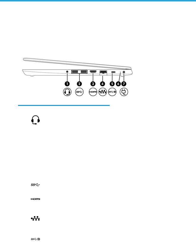
Right
Table 2-1 Right-side components and their descriptions
Component |
|
Description |
|
|
|
|
|
(1) |
Audio-out (headphone)/Audio-in (microphone) |
Connects optional powered stereo speakers, headphones, |
|
|
combo jack |
earbuds, a headset, or a television audio cable. Also connects an |
|
|
|
optional headset microphone. This jack does not support |
|
|
|
optional standalone microphones. |
|
|
|
WARNING! To reduce the risk of personal injury, adjust the |
|
|
|
volume before putting on headphones, earbuds, or a headset. |
|
|
|
For additional safety information, see the Regulatory, Safety, |
|
|
|
and Environmental Notices. |
|
|
|
To access this guide: |
|
|
|
▲ |
Type HP Documentation in the taskbar search box, |
|
|
|
and then select HP Documentation. |
|
|
NOTE: When a device is connected to the jack, the computer |
|
|
|
speakers are disabled. |
|
|
|
|
|
(2) |
USB SuperSpeed port |
Connects a USB device, such as a cell phone, camera, activity |
|
|
|
tracker, or smartwatch, and provides high-speed data transfer. |
|
|
|
|
|
(3) |
HDMI port |
Connects an optional video or audio device, such as a high- |
|
|
|
de |
nition television, any compatible digital or audio |
|
|
component, or a high-speed High De nition Multimedia |
|
|
|
Interface (HDMI) device. |
|
|
|
|
|
(4) |
RJ-45 (network) jack/status lights |
Connects a network cable. |
|
|
|
● |
Green (left): The network is connected. |
|
|
● |
Amber (right): Activity is occurring on the network. |
|
|
|
|
(5) |
USB Type-C power connector port, SuperSpeed |
Connects an AC adapter that has a USB Type-C connector, |
|
|
port, and DisplayPort™ connector |
supplying power to the computer and, if needed, charging the |
|
|
|
computer battery. |
|
– and –
6Chapter 2 Components

Table 2-1 Right-side components and their descriptions (continued)
Component |
|
Description |
|
|
|
|
|
|
|
Connects a USB device that has a Type-C connector, such as a |
|
|
|
cell phone, camera, activity tracker, or smartwatch, and |
|
|
|
provides high-speed data transfer. |
|
|
|
– and – |
|
|
|
Connects a display device that has a USB Type-C connector, |
|
|
|
providing DisplayPort output. |
|
|
|
NOTE: Cables, adapters, or both (purchased separately) might |
|
|
|
be required. |
|
|
|
|
|
(6) |
Battery light |
When AC power is connected: |
|
|
|
● |
White: The battery charge is greater than 90%. |
|
|
● |
Amber: The battery charge is from 0 to 90%. |
|
|
● |
O : The battery is not charging. |
When AC power is disconnected (battery not charging):
● Blinking amber: The battery has reached a low battery level. When the battery has reached a critical battery level, the battery light begins blinking rapidly.
● O : The battery is not charging.
(7) |
Power connector |
Connects an AC adapter. |
|
|
|
Right 7
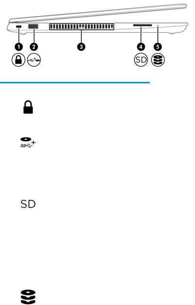
Left
Table 2-2 Left-side components and their descriptions
Component |
|
Description |
|
|
|
|
|
||
(1) |
Security cable slot |
Attaches an optional security cable to the computer. |
||
|
|
NOTE: The security cable is designed to act as a deterrent, but |
||
|
|
it may not prevent the computer from being mishandled or |
||
|
|
stolen. |
|
|
|
|
|
||
(2) |
USB powered port |
Connects and supplies power to a USB device, such as a cell |
||
|
|
phone, camera, activity tracker, optical drive, or smartwatch, |
||
|
|
and provides data transfer. |
|
|
|
|
|
||
(3) |
Vent |
Enables airflow to cool internal components. |
||
|
|
NOTE: The computer fan starts up automatically to cool |
||
|
|
internal components and prevent overheating. It is normal for |
||
|
|
the internal fan to cycle on and o |
during routine operation. |
|
|
|
|
||
(4) |
Memory card reader |
Reads optional memory cards that store, manage, share, or |
||
|
|
access information. |
|
|
|
|
To insert a card: |
|
|
|
|
1. |
Hold the card label-side up, with the connectors facing the |
|
|
|
|
computer. |
|
|
|
2. |
Insert the card into the memory card reader, and then |
|
|
|
|
press in on the card until it is |
rmly seated. |
|
|
To remove a card: |
|
|
|
|
▲ |
Press in on the card, and then remove it from the memory |
|
|
|
|
card reader. |
|
|
|
|
|
|
(5) |
Drive light |
● |
Blinking white: The hard drive is being accessed. |
|
|
|
● |
Amber: HP 3D DriveGuard has temporarily parked the hard |
|
|
|
|
drive. |
|
|
|
|
|
|
8Chapter 2 Components
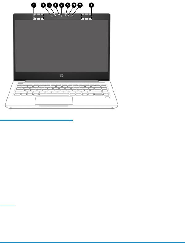
Display
Table 2-3 Display components and their descriptions
Component |
Description |
|
|
|
|
(1) |
WLAN antennas* (select products only) |
Send and receive wireless signals to communicate with wireless local area |
|
|
networks (WLANs). |
|
|
|
(2) |
Internal microphones |
Record sound. |
|
|
|
(3) |
Camera(s) (select products only) |
Allow(s) you to video chat, record video, and record still images. Some cameras |
|
|
also allow a facial recognition logon to Windows, instead of a password logon. |
|
|
NOTE: Camera functions vary depending on the camera hardware and |
|
|
software installed on your product. |
|
|
|
(4) |
Camera privacy cover (select products |
By default, the camera lens is uncovered, but you can slide the camera privacy |
|
only) |
cover to block the camera's view. To use the camera, slide the camera privacy |
|
|
cover in the opposite direction to reveal the lens. |
|
|
NOTE: If you have both front-facing and rear-facing cameras, when one |
|
|
camera lens is revealed and ready to use, the other is concealed. |
|
|
|
(5) |
Camera light (select products only) |
On: The camera is in use. |
*The antennas are not visible from the outside of the computer. For optimal transmission, keep the areas immediately around the antennas free from obstructions.
For wireless regulatory notices, see the section of the Regulatory, Safety, and Environmental Notices that applies to your country or region.
To access this guide:
▲ Type HP Documentation in the taskbar search box, and then select HP Documentation.
Display 9
Keyboard area
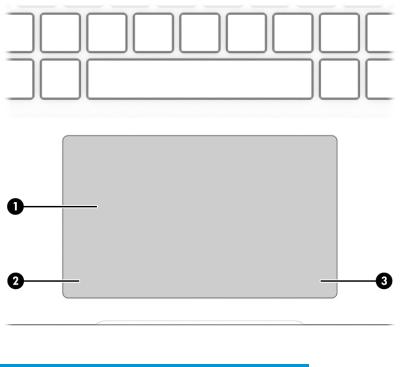
Touchpad
Table 2-4 Touchpad components and their descriptions
Component |
|
Description |
|
|
|
(1) |
Touchpad zone |
Reads your nger gestures to move the pointer or activate |
|
|
items on the screen. |
|
|
|
(2) |
Left touchpad button |
Functions like the left button on an external mouse. |
|
|
|
(3) |
Right touchpad button |
Functions like the right button on an external mouse. |
|
|
|
10 Chapter 2 Components
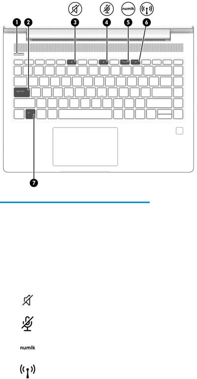
Lights
Table 2-5 Lights and their descriptions
Component |
|
Description |
|
|
|
|
|
(1) |
Power light |
● |
On: The computer is on. |
|
|
● |
Blinking: The computer is in the Sleep state, a power-saving |
|
|
|
state. The computer shuts o power to the display and |
|
|
|
other unneeded components. |
|
|
● |
O : The computer is o or in Hibernation. Hibernation is a |
|
|
|
power-saving state that uses the least amount of power. |
|
|
|
|
(2) |
Caps lock light |
On: Caps lock is on, which switches the key input to all capital |
|
|
|
letters. |
|
|
|
|
|
(3) |
Mute light |
● |
On: Computer sound is o . |
|
|
● |
O : Computer sound is on. |
|
|
|
|
(4) |
Microphone mute light |
● |
On: Microphone is o . |
|
|
● |
O : Microphone is on. |
|
|
|
|
(5) |
Num lk light |
On: Num lock is on. |
|
|
|
|
|
(6) |
Wireless light |
On: An integrated wireless device, such as a wireless local area |
|
|
|
network (WLAN) device and/or a Bluetooth® device, is on. |
|
|
|
NOTE: On some models, the wireless light is amber when all |
|
|
|
wireless devices are o . |
|
|
|
|
|
(7) |
Fn lock light |
On: The fn key is locked. |
|
|
|
|
|
Keyboard area 11
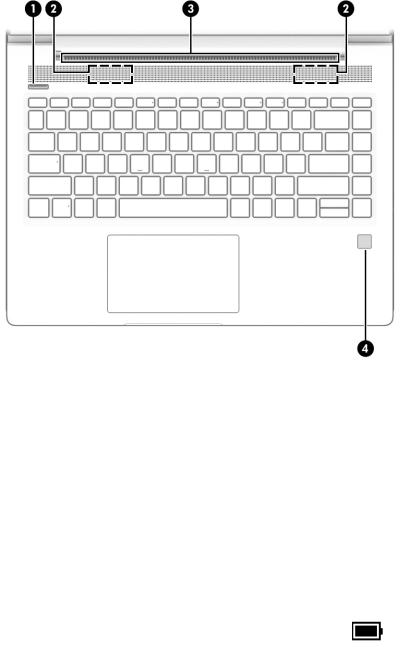
Button, speakers, and ngerprint sensor
Table 2-6 Button, vent, speakers, |
ngerprint reader, and their descriptions |
||
|
|
||
Component |
Description |
||
|
|
|
|
(1) |
Power button |
● |
When the computer is o , press the button to turn on the computer. |
|
|
● |
When the computer is on, press the button briefly to initiate Sleep. |
|
|
● |
When the computer is in the Sleep state, press the button briefly to exit Sleep (select |
|
|
|
products only). |
|
|
● |
When the computer is in Hibernation, press the button briefly to exit Hibernation. |
IMPORTANT: Pressing and holding down the power button results in the loss of unsaved information.
If the computer has stopped responding and shutdown procedures are ine ective, press and hold the power button for at least 4 seconds to turn o the computer.
To learn more about your power settings, see your power options.
|
|
▲ |
Right-click the Power meter icon |
and then select Power Options. |
|
|
|
|
|
(2) |
Speakers (2) |
Produce sound. |
|
|
|
|
|
||
(3) |
Vent |
Enables airflow to cool internal components. |
||
|
|
NOTE: The computer fan starts up automatically to cool internal components and prevent |
||
|
|
overheating. It is normal for the internal fan to cycle on and o during routine operation. |
||
|
|
|
||
(4) |
Fingerprint reader (select |
Allows a ngerprint logon to Windows, instead of a password logon. |
||
|
products only) |
▲ |
Swipe down across the ngerprint reader. |
|
|
|
|||
|
|
|
IMPORTANT: To prevent ngerprint logon issues, be sure when you register your |
|
|
|
|
ngerprint that all sides of your |
nger are registered by the ngerprint reader. |
|
|
|
|
|
12 Chapter 2 Components
Special keys
Table 2-7 Special keys and their descriptions
Component |
|
Description |
|
|
|
(1) |
esc key |
Displays system information when pressed in combination with the fn key. |
|
|
|
(2) |
fn key |
Executes frequently used system functions when pressed in combination with |
|
|
another key. Such key combinations are called hot keys. |
|
|
|
(3) |
Windows key |
Opens the Start menu. |
|
|
NOTE: Pressing the Windows key again closes the Start menu. |
|
|
|
(4) |
Action keys |
Execute frequently used system functions. |
|
|
|
(5) |
Embedded numeric keypad |
A numeric keypad superimposed over the keyboard alphabet keys. When fn+num |
|
|
lk is pressed, the keypad can be used like an external numeric keypad. Each key on |
|
|
the keypad performs the function indicated by the icon in the upper-right corner |
|
|
of the key. |
|
|
NOTE: If the keypad function is active when the computer is turned o , that |
|
|
function is reinstated when the computer is turned back on. |
|
|
|
(6) |
Windows application key |
Displays options for a selected object. |
|
|
|
(7) |
num lk key |
Turns the embedded numeric keypad on and o when pressed in combination |
with the fn key.
– or –
Turns the embedded numeric keypad on and o .
Keyboard area 13
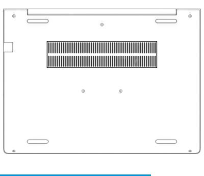
Bottom
Table 2-8 Bottom component and description
Component |
Description |
|
|
Vent |
Enables airflow to cool internal components. |
|
NOTE: The computer fan starts up automatically to cool internal |
|
components and prevent overheating. It is normal for the internal |
|
fan to cycle on and o during routine operation. |
|
|
14 Chapter 2 Components
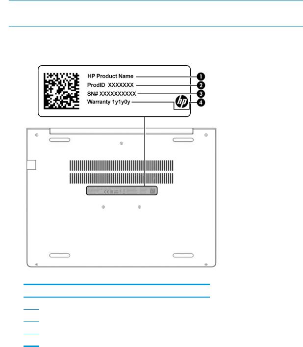
Labels
The labels affixed to the computer provide information you may need when you troubleshoot system problems or travel internationally with the computer. Labels may be in paper form or imprinted on the product.
 IMPORTANT: Check the following locations for the labels described in this section: the bottom of the computer, inside the battery bay, under the service door, on the back of the display, or on the bottom of a tablet kickstand.
●Service label—Provides important information to identify your computer. When contacting support, you may be asked for the serial number, the product number, or the model number. Locate this information before you contact support.
Table 2-9 Service label components
Component
(1)HP product name
(2)Product ID
(3)Serial number
(4)Warranty period
●Regulatory label(s)—Provide(s) regulatory information about the computer.
●Wireless certi cation label(s)—Provide(s) information about optional wireless devices and the approval markings for the countries or regions in which the devices have been approved for use.
Labels 15

3Illustrated parts catalog
Computer major components
 NOTE: HP continually improves and changes product parts. For complete and current information about supported parts for your computer, go to http://partsurfer.hp.com, select your country or region, and then follow the on-screen instructions.


 NOTE: Details about your computer, including model, serial number, product key, and length of warranty, are on the service tag at the bottom of your computer. See Labels on page 15 for details.
16 Chapter 3 Illustrated parts catalog

Table 3-1 Computer major components and their descriptions
Item |
Description |
Spare part number |
|
|
|
(1) |
Display panel assembly |
not available as a spare |
|
NOTE: Display panels are only available as spare parts at a subcomponent level. |
part |
|
|
(2)Top cover/keyboard (includes cable)
NOTE: For a detailed list of keyboard country codes, see Keyboard/top cover on page 65.
|
With backlight |
L65224-001 |
|
|
|
|
No backlight |
L65225-001 |
|
|
|
|
With backlight, privacy |
L79440-001 |
|
|
|
(3) |
Touchpad (includes cable) |
L77252-001 |
|
|
|
(4) |
Fingerprint sensor assembly |
L77229-001 |
|
NOTE: The ngerprint sensor cable is available in the Cable Kit as spare part number |
|
|
M04397-001. |
|
|
|
|
(5) |
RTC battery |
L02772-001 |
|
|
|
(6) |
USB board (includes cable) |
L44578-001 |
|
NOTE: The USB board cable is available in the Cable Kit as spare part number M04397-001. |
|
|
|
|
(7) |
Speaker assembly |
L44554-001 |
|
|
|
(8) |
Card reader board (includes cable) |
L52223-001 |
|
NOTE: The card reader board cable is also available in the Cable Kit as spare part number |
|
|
M04397-001. |
|
(9)System board (includes integrated processor and replacement thermal material) All system boards use the following part numbers:
xxxxxx-001: Non-Windows operating system xxxxxx-601: Windows 10 operating system
|
AMD Ryzen 7 PRO 4750U processor |
M09523-xx1 |
|
|
|
|
AMD Ryzen 5 PRO 4650U processor |
M09522-xx1 |
|
|
|
|
AMD Ryzen 7 4700U processor |
L98556-xx1 |
|
|
|
|
AMD Ryzen 5 4500U processor |
L98554-xx1 |
|
|
|
|
AMD Ryzen 3 4300U processor |
L98552-xx1 |
|
|
|
(10) |
Heat sink (includes replacement thermal material) |
L52217-001 |
|
|
|
(11) |
Power connector cable |
L01048-001 |
|
|
|
(12) |
WLAN module |
|
|
|
|
|
Intel Dual Band Wireless-AC 9260 802.11ac 2 × 2 Wi-Fi + Bluetooth 5.0 Combo Adaptor (non-vPro) |
L16647-002 |
|
|
|
|
Intel Wi-Fi 6 AX200 802.11ax 2 × 2 + Bluetooth 5.0 (non-vPro) |
L35282-002 |
|
|
|
|
Realtek RTL8822CE 802.11ac 2 × 2 Wi-Fi + Bluetooth 5.0 |
L44796-002 |
|
|
|
(13) |
Fan |
L44556-001 |
(14)Memory module (DDR4-3200)
Computer major components 17

Table 3-1 Computer major components and their descriptions (continued)
Item |
Description |
Spare part number |
|
|
|
|
16 GB |
L67710-002 |
|
|
|
|
8 GB |
L46598-002 |
|
|
|
|
4 GB |
L83673-002 |
|
|
|
(15) |
M.2 solid-state drive |
|
|
|
|
|
512 GB, PCIe, TLC |
L85360-002 |
|
|
|
|
512 GB, PCIe, value |
L85364-002 |
|
|
|
|
256 GB, PCIe, value |
L85354-002 |
|
|
|
|
256 GB, SATA-3, TLC |
938184-852 |
|
|
|
|
128 GB, SATA-3, TLC |
L85346-002 |
|
|
|
(16) |
Battery (3 cell, 45 Whr) |
L32656-005 |
|
|
|
(17) |
Hard drive |
|
|
|
|
|
1 TB, 5400 rpm, 7 mm |
L30422-002 |
|
|
|
|
500 GB, 7200 rpm, 7 mm |
703267-002 |
|
|
|
(18) |
Bottom cover |
L44558-001 |
|
|
|
18 Chapter 3 Illustrated parts catalog

Display components
Table 3-2 Display components and their descriptions
Item |
Description |
Spare part number |
|
|
|
(1) |
Display bezel |
|
|
|
|
|
For use in models without a camera |
L78090-001 |
|
|
|
|
For use in models with an HD camera |
L78091-001 |
|
|
|
|
For use in models with an HD + IR camera |
L78092-001 |
|
|
|
(2) |
Display panel (raw) (includes bezel adhesive and display enclosure adhesive) |
|
|
|
|
|
HD panel |
L98562-001 |
|
|
|
|
FHD panel, nonprivacy |
L98563-001 |
|
|
|
|
FHD panel. privacy |
L98564-001 |
|
|
|
(3) |
Display/camera cable assembly, HD models (included in Display Cable Kit) |
L78088-001 |
|
|
|
(4) |
Camera module, HD (includes bezel adhesive and display enclosure adhesive) |
L81889-001 |
|
|
|
Display components 19
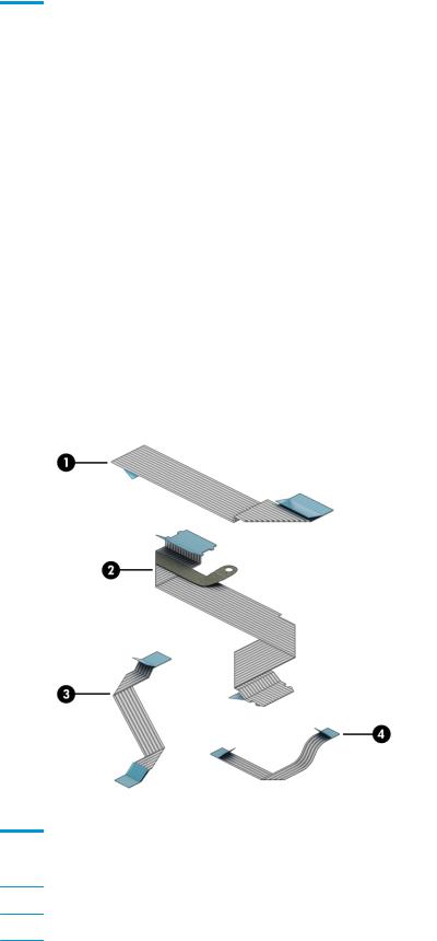
Table 3-2 Display components and their descriptions (continued)
Item |
Description |
Spare part number |
|
|
|
(5) |
Display/camera cable assembly, HD + IR models (included in Display Cable Kit) |
L78088-001 |
|
|
|
(6) |
Camera module, HD + IR (includes bezel adhesive and display enclosure adhesive) |
L81890-001 |
|
|
|
|
Microphone board |
M09340-001 |
|
|
|
(7) |
WLAN antennas (includes bezel adhesive and display enclosure adhesive) |
L78070-001 |
|
|
|
(8) |
Hinge Kit (left and right hinges; includes bezel adhesive and display enclosure adhesive) |
|
|
|
|
|
For use in nonprivacy models |
L78093-001 |
|
|
|
|
For use in privacy models |
L91017-001 |
|
|
|
(9) |
Display rear cover (includes wireless antennas and bezel adhesive) |
|
|
|
|
|
Models with a nonprivacy display and HD camera |
L78072-001 |
|
|
|
|
Models with a privacy display |
L78074-001 |
|
|
|
|
Models with a nonprivacy display and HD+ camera |
L78075-001 |
|
|
|
|
Camera privacy cover (not illustrated) |
L77237-001 |
|
|
|
Cable Kit
Table 3-3 Cable Kit components and their descriptions
Item |
Description |
Spare part number |
|
|
|
|
Cable Kit, includes the following parts: |
M04397-001 |
(1)USB board cable
(2)Card reader board cable
20 Chapter 3 Illustrated parts catalog
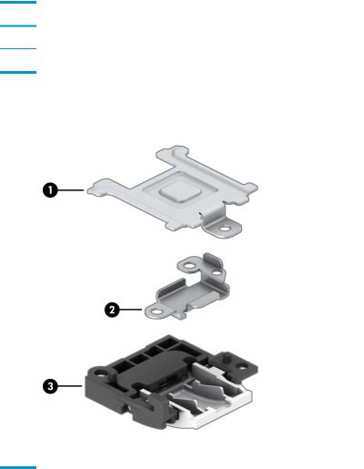
Table 3-3 Cable Kit components and their descriptions (continued)
Item |
Description |
Spare part number |
(3)Touchpad cable
(4)Fingerprint sensor cable
Bracket Kit
Table 3-4 Bracket Kit components and their descriptions
Item |
Description |
Spare part number |
|
|
|
|
Bracket Kit, includes the following parts: |
L77264-001 |
|
|
|
(1) |
Fingerprint sensor bracket |
|
|
|
|
(2) |
USB Type-C port bracket |
|
|
|
|
(3) |
RJ-45 (network) jack bracket |
|
|
|
|
|
Fingerprint sensor insert (for use in models without a |
ngerprint sensor; not illustrated) |
|
|
|
Bracket Kit 21
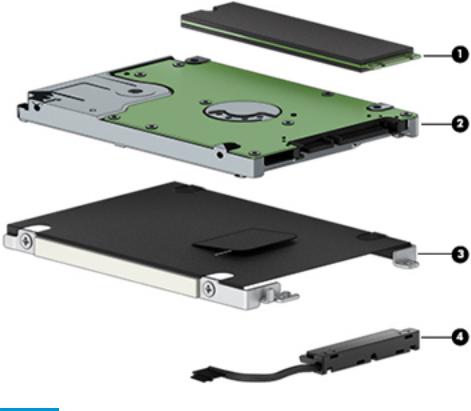
Mass storage devices
Table 3-5 Mass storage devices and their descriptions
Item |
Description |
Spare part number |
|
|
|
(1) |
Solid-state drive, M.2 |
|
|
|
|
|
512 GB, PCIe, TLC |
|
|
|
|
|
512 GB, PCIe, value |
L85364-002 |
|
|
|
|
256 GB, PCIe, value |
L85354-002 |
|
|
|
|
256 GB, SATA-3, TLC |
938184-852 |
|
|
|
|
128 GB, SATA-3, TLC |
L85346-002 |
|
|
|
(2) |
Hard drive |
|
|
|
|
|
1 TB, 5400 rpm, 7 mm |
L30422-002 |
|
|
|
|
500 GB, 7200 rpm, 7 mm |
703267-002 |
|
|
|
|
Hard Drive Hardware Kit, includes the following parts: |
L44510-001 |
|
|
|
(3) |
Hard drive cover |
|
|
|
|
(4) |
Hard drive cable |
|
|
|
|
22 Chapter 3 Illustrated parts catalog
Loading...