


T775J
Electronic Remote Temperature Controller
GENERAL
The T775J family of electronic remote temperature controllers provides reset control for chillers, heating and cooling systems, and other applications where electronic accuracy in addition to remote sensing is desired.
PRODUCT DATA
FEATURES
•T775 model provides reset control with two
temperature inputs and one of either 4 to 20 mA, 0 to 18 Vdc, or Electronic Series 90a Proportional + Integral modulating output with 0 or 1 relay output stages, or 1 or 2 relay output stages with no modulation.
•-40°F to +220°F (-40°C to +105°C) setpoint temperature range.
•-45°F to +225°F (-43°C to +107°C) sensor display range.
•-30°F to + 140°F (-34°C to +60°C) ambient temperature range.
•Linear platinum temperature sensor.
•Adjustable temperature range and differential.
•Adjustable throttling range of 2° to 30° F or C.
•Adjustable reset ratio.
•Liquid crystal display (LCD) indication for mode and output status.
•Keypad provides ease of programming and operation.
•Accuracy is within +/- 1°F/C at nominal input voltage, nominal sensor ambient temperature (77°F (25°C) operating ambient). Accuracy can vary as parameters deviate from nominal.
•Stages independently programmed for heating or cooling.
•24/120/240 Vac voltage inputs.
•Spdt relay outputs.
IMPORTANT
The T775 is an operating control, not a limit or safety control. When used in applications requiring safety or limit controls, use a separate safety or limit control device in conjunction with the T775.
aThe Electronic Series 90 output provided with T775J models will not drive electromechanical Series 90 slidewire devices.
|
Contents |
General ............................................................................... |
1 |
Features .............................................................................. |
1 |
Specifications ...................................................................... |
2 |
Ordering Information ........................................................... |
2 |
Installation ........................................................................... |
3 |
Description/Operation ......................................................... |
13 |
Checkout ............................................................................. |
18 |
Copyright © 1995 Honeywell Inc. • All Rights Reserved |
63-2248-4 |

T775J ELECTRONIC REMOTE TEMPERATURE CONTROLLER
SPECIFICATIONS
IMPORTANT
The specifications given in this publication do not include normal manufacturing tolerances. Therefore, an individual unit may not exactly match the listed specifications. Also, this product is tested and calibrated under closely controlled conditions and some minor differences in performance can be expected if those conditions are changed.
Models (See Table 1):
The T775J family of electronic remote temperature controls provides reset control for chillers, heating and cooling systems, and other applications where electronic accuracy in addition to remote sensing is desired.
T775J provides reset control with two temperature inputs and one of either 4 to 20 mA, Electronic Series 90, or 0 to 18 Vdc Proportional + Integral modulating output with 0 or 1 relay output stages, or 1 to 2 relay output stages with no modulation. Includes two part number 193987GA
Sensors.
Table 1. T775J Model Numbers and Outputs.
|
|
|
|
|
|
Outputs |
|
|
|
|
|
Model |
Modulation |
|
Number of Relay |
Number |
Type |
|
Outputs |
|
|
|
|
T775J1001 |
None |
|
1 |
|
|
|
|
T775J1019 |
Series 90 |
|
0 |
|
|
|
|
T775J1027 |
4-20 mA |
|
0 |
|
|
|
|
T775J1035 |
0-18 Vdc |
|
0 |
|
|
|
|
T775J1043 |
Series 90 |
|
1 |
|
|
|
|
T775J1050 |
4-20 mA |
|
1 |
|
|
|
|
T775J1068 |
0-18 Vdc |
|
1 |
|
|
|
|
T775J1076 |
None |
|
2 |
|
|
|
|
Electrical Ratings:
Voltage Input: 24/120/240 Vac, 50/60 Hz (+10/-15%).
Power Consumption:
50 Hz: 10 VA maximum.
60 Hz: 8 VA maximum.
Contact Ratings:
1/2 HP: 9.8 FLA, 58.8 LRA at 120 Vac. 1/2 HP: 4.9 FLA; 29;4 LRA at 240 Vac. 125 VA pilot duty at 120/240 Vac.
10A at 24 Vac (resistive).
Temperature Accuracy:
±1° F (0.6° C) (at nominal input voltage, 77°F (25°C) operating ambient, nominal sensor ambient).
Setpoint Adjustment Range:
-40° F to +220° F (-40° C to +105° C).
Operating Ambient Temperature:
Controller: -30°F to + 140°F (-34°C to 60°C). Sensor: -45°F to + 225°F (-43°C to 107°C).
Throttling Range for Modulating Output:
Adjustable 2° to 30° F or C.
Differential Range for Staged Output:
Adjustable 1° to 30° F.
Reset Ratio:
Adjustable between 1 to 30 and 30 to 1.
Operating Humidity:
5 to 95 percent relative humidity, noncondensing.
Sensor:
Positive coefficient platinum type, 4.8 ohms/°F, 1000 feet maximum distance between sensor and solid state controller (requires calibration over 400 feet).
Approvals:
Underwriters Laboratories Inc. Listed: File No. E4436.
Guide XAPX.
Canadian Standards Association Certified: File No.
LR47125.
ORDERING INFORMATION
When purchasing replacement and modernization products from your TRADELINE® wholesaler or distributor, refer to the TRADELINE® Catalog or price sheets for complete ordering number .
1.Model Number
2.Accessory
If you have additional questions, need further information, or would like to comment on our products or services, please write or phone:
1.Your local Home and Building Control Sales Office (check white pages of your phone directory).
2.Home and Building Control Customer Logistics Honeywell Inc., 1885 Douglas Drive North Minneapolis, Minnesota 55422-4386
In Canada—Honeywell Limited/Honeywell Limitée, 35 Dynamic Drive, Scarborough, Ontario M1V 4Z9. International Sales and Service Offices in all principal cities of the world. Manufacturing in Australia, Canada, Finland, France, Germany, Japan, Mexico, Netherlands, Spain, Taiwan, United Kingdom, U.S.A.
63-2248—4 |
2 |
T775J ELECTRONIC REMOTE TEMPERATURE CONTROLLER
Mounting:
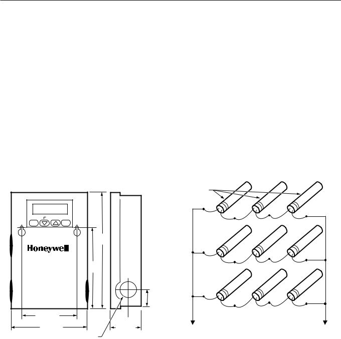
Mounts on any suitable horizontal or vertical surface. (See Fig. 5 for mounting hole locations.)
Dimensions:
See Fig. 1.
Display Resolution:
Sensed temperature and other operating parameters are displayed via a liquid crystal display (LCD) with a resolution of 1°F or 1°C.
Accessories:
C7100C1003 Duct Mount Averaging Sensor*. T7047C1090 Wall Mount Sensor Case. 107324A Bulb Holder, duct insertion. 121371A Copper Immersion Well.
121371E Stainless Steel Immersion Well.
107408 Heat Conduction Compound, 4 ounce. C7043A1098 Case and Immersion Well. 203401B Waterproof Sensor.
203531A Panel Mounting Kit.
A775A1003 Sensor Simulator.
*Use of C7100C1003 decreases accuracy of T775 to ±2°F (±1°C).
SELECT SET  ENTER
ENTER
8-1/2
(216)
5-7/32
(134)
1-1/4
(32)
3-13/16 (97)
 1-1/4
1-1/4  (32)
(32)
4-3/4 (121) |
2-3/8 (60) |
7/8 (22) DIAMETER |
M344C |
|
Fig. 1. Approximate T775J dimensions in in. (mm).
INSTALLATION
When Installing this Product...
Read these instructions carefully. Failure to follow them could damage the product or cause a hazardous condition.
Check the ratings given in these instructions and on the product to make sure the product is suitable for your application.
Installer must be a trained, experienced service technician.
After installation is complete, check out the product operation as provided in these instructions.
 CAUTION
Disconnect power before installation to prevent electrical shock or equipment damage.
Location and Mounting
Mount the controller in any convenient interior location using the two mounting holes provided. Mounting screws are not included. Use controller dimensions in Fig. 1 as a guide.
Sensor Location
The 193987GA Sensor can be used up to 1000 ft (304m) from the T775 using standard AWG 18/2 unshielded wire. If longer than 25 feet in an electrically noisy environment, use shielded cable. Locate the sensor on pipes, in immersion wells, in wall-mounted cases or on a bulb holder.
Multiple sensors can be parallel-series wired to sense average temperature in large spaces. In order to maintain control accuracy, be sure the number of sensors parallelseries wired is of the n2 power (i.e., 1, 4, 9, 16, etc). See Fig. 2.
SENSORS
TO T775 CONNECTIONS 1 AND 2 (SENSOR A) |
|
OR 7 AND 8 (SENSOR B). |
M7431 |
|
Fig. 2. Parallel-series wiring of sensors.
Sensor Mounting
Mount the sensor on a wall or panel for sensing space temperature (Fig. 3); strap it to a pipe, or insert it into a well (Fig. 4) for hot/cold water sensing; or tape it to a standard cap or bulb holder for duct air sensing. To prevent moisture or condensation entering the sensor through the leadwire holes, mount the sensor with leadwires exiting the bottom of the sensor.
NOTE: Use heat conductive compound in immersion wells. See Accessories.
3 |
63-2248—4 |
T775J ELECTRONIC REMOTE TEMPERATURE CONTROLLER
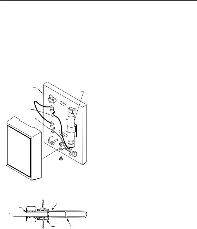
Mounting Sensor in T7047C1090 Case
Run wires from T775J through wall.
Mount case to wall with screws provided.
Connect wires from the T775J to two T terminals on the T7047C Case.
Cut and strip 193987GA Sensor leads to 3 to 4 inch (76 to 102 mm) length and connect to T terminals in the case.
Position sensor as shown in Fig. 3; assemble cover and tighten cover screws.
 CAUTION
1 . Make sure that metal tube of sensor does not short against T terminals in wall-mounted case.
2.Do not run sensor wiring (even if using shielded cable) with building power wiring.
T7047C1090 WALLMOUNT SENSOR
CASE (OPTIONAL)
193987GA SENSOR
LEADWIRES
TO T775
SCREW
TERMINAL
SCREW
TERMINAL
CAUTION: POSITION SENSOR AWAY
FROM SCREW TERMINALS.
M8109C
Fig. 3. Sensor mounted on wall.
COVER SENSOR |
|
|
|
LEADS WITH |
SENSOR PLACED |
||
HEAT CONDUCTIVE |
|||
IN WELL |
|
||
COMPOUND |
|
||
|
|
||
|
1/2 NPT |
IMMERSION |
|
|
|
WELL |
|
|
|
M5249 |
|
Fig. 4. Sensor inserted in immersion well.
Wiring
 CAUTION
Disconnect external power before wiring to prevent electrical shock or equipment damage.
IMPORTANT
The T775J is not intended for safety limit applications. It is an operating control, not a safety control.
Disconnect external power before wiring to prevent electrical shock or equipment damage. All wiring must comply with applicable local codes and ordinances.
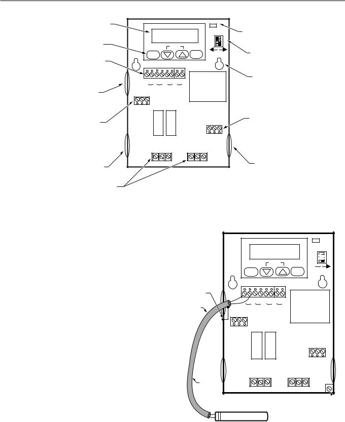
Refer to Fig. 4 for locating the appropriate power inputs, remote sensor inputs, relay, modulating output terminals, contact closure input, and sensor selection switch. Access the terminals through standard conduit knockouts (A-C) located around the enclosure perimeter.
NOTE: Hole A should only be used for remote sensor wiring, low voltage wiring, and access to modulating output.
When wiring the input power, only one source of power can be applied to the T775J (e.g., 24 or 120 or 240 Vac). Knockouts B and C can be used to gain access to 120 or 240 Vac input terminals and the load relay output terminals.
The T775J can be used to provide reset control of damper and valve actuators that accept 4 to 20 mA, 0 to 18 Vdc or Electronic Series 90 modulating inputs, and to control one onoff load. Depending on the application and the motor or actuator used, the T775J can control up to three Modutrol motors by using resistor kits that are available as accessories for existing motors. Use specified resistor kits to control an Electronic Series 90 (Modutrol®) Motor with a 4 to 20 mA controller. Obtain information on these kits from either the TRADELINE® catalog, motor specification or your local distributors. See Fig. 7 through 15 for typical T775J wiring and applications.
63-2248—4 |
4 |
T775J ELECTRONIC REMOTE TEMPERATURE CONTROLLER
LCD |
|
|
|
|
|
|
|
|
|
|
|
|
|
|
TEMPERATURE |
|
|
|
|
|
|
|
|
|
C/F |
|
|
|
|
DISPLAY |
|
|
|
|
|
|
|
|
|
|
|
|
||
|
|
|
|
|
|
|
|
|
|
|
|
|
|
|
|
|
|
|
|
|
|
|
|
|
|
|
|
|
OC / OF SELECTION |
PROGRAMMING |
|
|
|
|
|
|
|
|
|
|
|
|
12 |
|
KEYS |
|
SELECT |
|
SET |
|
ENTER |
|
|
4 3 |
|
||||
|
|
|
|
|
|
|
|
|||||||
SENSOR INPUT, |
|
|
|
|
|
|
|
|
|
SA |
|
SB |
RESET DIP |
|
TOD, AND |
|
|
|
|
|
|
|
|
|
|
SWITCHES |
|||
|
|
|
|
|
|
|
|
|
|
|
|
|
||
24V TERMINALS |
|
|
|
|
|
|
|
|
|
|
|
|
|
|
|
|
|
|
|
|
|
|
|
|
|
|
|
|
MOUNTING |
|
|
1 |
2 |
3 |
4 |
5 |
6 |
7 |
8 |
|
|
|
|
HOLE |
|
|
SA |
TOD 24V |
SB |
|
|
|
|
LOCATION |
|||||
KNOCKOUT "A" |
|
|
|
|
|
|
||||||||
2 |
1 |
|
|
|
|
|
|
|
|
|
|
|
|
|
3 |
|
|
|
|
|
|
|
|
|
|
|
|
||
MODULATING OUTPUT |
|
|
|
|
|
|
|
|
|
|
|
|
|
|
ELECTRONIC |
|
|
|
|
|
|
|
|
|
|
|
|
|
|
SERIES 90, 4-20 mA |
|
|
|
|
|
|
|
|
|
|
|
|
|
|
OR 0-18 VDC |
|
|
|
|
|
|
|
|
|
240V |
COM |
120V |
|
LINE |
DEPENDING ON MODEL |
|
|
|
|
|
|
|
|
|
|
VOLTAGE |
|||
|
|
|
|
|
|
|
|
|
|
|
|
|
|
INPUTS |
|
|
|
OUTPUT 1 |
|
|
OUTPUT 2 |
|
|
|
|
||||
KNOCKOUT "B" |
|
|
NO COM NC |
|
|
|
NO COM NC |
|
|
|
KNOCKOUT "C" |
|||
|
|
|
|
|
|
|
|
|
|
|
|
|
|
|
RELAY OUTPUT |
|
|
|
|
|
|
|
|
|
|
|
|
|
|
STAGES |
|
|
|
|
|
|
|
|
|
|
|
|
|
M8118 |
|
|
|
|
|
|
|
|
|
|
|
|
|
|
|
Fig. 5. Feature locations.
IMPORTANT
Erratic temperature readings from the 193987GA Sensor can be caused by poor wiring practices that must be avoided to assure proper operation:
a.Do not route temperature sensor wiring with building power wiring.
b.Do not locate temperature sensor wiring next to control contactors.
c.Do not locate temperature sensor wiring near electric motors.
d.Do not locate temperature sensor wiring near welding equipment.
e.Make sure good mechanical connections are made to both the sensor and the controller.
f.Do not mount sensor with leadwire end (wire end) pointing up in an area where condensation can
occur.
g.Use shielded wiring to connect the sensor to the T775 when an electrically noisy environment exists. See Fig. 6.
T775
SELECT SET
GROUND
SHIELD
TO T775 CASE OR TO GROUNDING SCREW
SHIELDED |
|
1 |
2 |
3 |
4 |
5 |
6 |
7 |
8 |
CABLE |
|
SA |
TOD 24V |
SB |
|||||
|
|
||||||||
3 |
2 |
1 |
|
|
|
|
|
|
|
|
OUTPUT 1 |
SHIELDED |
|
CABLE |
NO COM NC |
|
NOTE: DO NOT GROUND SHIELDED CABLE AT
SENSOR END. SENSOR
C/F


 312 ENTER
  4
4
SA SB
240V |
120V COM |
OUTPUT 2
NO COM NC
GROUNDING SCREW
NOTE: TO MINIMIZE NOISE PICKUP, MAKE CONNECTION
FROM SHIELDED CABLE AS CLOSE AS POSSIBLE M4718 TO SENSOR BODY.
Fig. 6. Using shielded cable for cable runs longer than 25 feet.
5 |
63-2248—4 |

T775J ELECTRONIC REMOTE TEMPERATURE CONTROLLER
|
|
|
|
|
|
|
C/F |
|
|
|
|
|
SELECT |
SET |
ENTER |
|
4 3 2 1 |
||
|
|
|
|
|
|||||
|
|
|
|
|
|
|
|
SA |
SB |
SENSOR A |
|
1 |
2 3 4 5 |
6 |
7 8 |
|
|
|
|
|
24 VAC |
|
SA TOD 24V |
SB |
|
|
|
||
SENSOR B |
|
|
|
|
|||||
2 |
1 |
|
|
|
|
|
|
||
|
3 |
|
|
|
|
|
|
||
|
|
|
|
|
|
|
240V |
COM |
120V |
LOAD 1 |
LOAD 2 |
|
|
|
|
|
|
|
|
|
|
|
|
OUTPUT 1 |
|
OUTPUT 2 |
|
|
|
|
|
|
|
NO COM NC |
|
|
NO COM NC |
|
|
|
|
|
|
|
|
|
|
|
M8111 |
Fig. 7. Reset control with 24 Vac input, 24 Vac loads.
SENSOR A
SENSOR B
|
|
|
|
|
|
|
|
|
C/F |
|
|
|
|
SELECT |
|
SET |
ENTER |
|
4 3 2 1 |
||||
|
|
|
|
|
|||||||
|
|
|
|
|
|
|
|
|
|
SA |
SB |
|
|
1 |
2 |
3 |
4 |
5 |
6 |
7 |
8 |
|
|
|
|
SA |
TOD 24V |
SB |
|
|
|||||
3 |
2 |
1 |
|
|
|
|
|
|
|
|
|
|
|
|
|
|
|
|
|
|
240V |
COM |
120V |
|
|
|
|
|
|
|
|
|
|
|
BLK |
|
|
|
OUTPUT 1 |
|
OUTPUT 2 |
|
120 VAC |
||||
|
|
|
|
|
|
|
|
|
|
|
WHT |
|
|
|
NO COM NC |
|
|
NO COM NC |
|
|
|||
LOAD 1 |
LOAD 2
M8112
Fig 8. Reset control with 120 Vac input, 120 Vac loads.
SENSOR A
SENSOR B
|
|
|
|
|
|
|
|
|
C/F |
|
|
|
|
SELECT |
|
SET |
ENTER |
|
4 3 2 1 |
||||
|
|
|
|
|
|||||||
|
|
|
|
|
|
|
|
|
|
SA |
SB |
|
|
1 |
2 |
3 |
4 |
5 |
6 |
7 |
8 |
|
|
|
|
SA |
TOD 24V |
SB |
|
|
|||||
3 |
2 |
1 |
|
|
|
|
|
|
|
|
|
|
|
|
|
|
|
|
|
|
240V |
COM |
120V |
|
|
|
|
|
|
|
|
|
|
|
BLK |
|
|
|
OUTPUT 1 |
|
OUTPUT 2 |
|
240 VAC |
||||
|
|
|
|
|
|
|
|
|
|
|
RED |
|
|
|
NO COM NC |
|
|
NO COM NC |
|
|
|||
LOAD 1 |
LOAD 2
M8113
Fig. 9. Reset control with 240 Vac input, 240 Vac loads.
SENSOR A
SENSOR B
|
|
|
|
|
|
|
|
|
C/F |
|
|
|
|
SELECT |
|
SET |
ENTER |
|
4 3 12 |
||||
|
|
|
|
|
|||||||
|
|
|
|
|
|
|
|
|
|
SA |
SB |
|
|
1 |
2 |
3 |
4 |
5 |
6 |
7 |
8 |
|
|
|
|
SA |
TOD 24V |
SB |
|
|
|||||
3 |
2 |
1 |
|
|
|
|
|
|
|
|
|
|
|
|
|
|
|
|
|
|
240V |
COM |
120V |
|
|
|
|
|
|
|
|
|
|
|
BLK |
|
|
|
OUTPUT 1 |
|
OUTPUT 2 |
|
120 VAC |
||||
|
|
|
|
|
|
|
|
|
|
|
WHT |
|
|
|
NO COM NC |
|
|
NO COM NC |
|
|
|||
LOAD 1 |
LOAD 2 |
24 VAC |
M8114
Fig. 10. Reset control with 120 Vac input, 24 Vac loads.
63-2248—4 |
6 |
 Loading...