


T8078C
LOW VOLTAGE MODULATING CONTROLLER
APPLICATIONS
The T8078C digital electronic controller is designed for individual zone control of terminal units in fan coil and air conditioning systems.
The controller provides position control of valves or dampers (for airside control), and is capable of mounting on a switching sub-base for manual control of the fan speed.
T8078C has great applications flexibility built-in – all applications and control modes can be selected simply by setting a bank of switches inside the product. Control parameters are also adjusted by means of onboard switches.
T8078C also supports a number of features that enhance the applications capability. These include remote sensing, energy savings mode (activated from an external input), remote setpoint adjustment, and heat/cool changeover.
Installation and commissioning are assisted by a special fast commissioning checkout sequence, internal valve synchronisation, simple user diagnostic LED indication, and the provision of a diagnostic output.
PRODUCT SPECIFICATION SHEET
FEATURES
•Modern styling makes T8078C ideal for locating in the occupied space, particularly in offices and hotels.
•Proportional + Integral (P+I) control form ensures close temperature control under all operating conditions.
•Control modes and applications configured by onboard switches.
•Choice of control Modes:
-3-position modulating
-thermal predictive modulating (TPM)
-On/off
•Choice of Applications:
-2-pipe fan-coil cooling
-2-pipe fan-coil heating
-2-pipe fan-coil cooling +2-stage on/off heating
-2-pipe fan-coil heating +2-stage on/off cooling
-2-pipe fan-coil heat/cool changeover
-4-pipe fan-coil heat + cool in sequence
•Choice of control parameters:
-1, 2, or 4 K for the Proportional Band
-2, 4 K for the Zero Energy Band
•Automatic heat/cool changeover is achieved by using a remote switch, or a pipe thermostat (S4390A1004) on the supply water pipe.
•Control setpoint can be remotely adjusted by ±5 K.
•Energy Savings Input - a local contact closure or a central voltage input will switch T8087C to Energy Savings Mode, where the cooling and heating setpoints will change to pre-defined setup and setback temperatures, enabling maximum energy efficiency. Setup/setback values can be set 2-8K by means of an on-board potentiometer.
•Sensor options: On-board or external (Wall mounted, or Remote/return air). The connection of an external sensor is detected automatically.
•Valve commissioning sequence for fast system check.
•Periodic valve exercise and synchronisation.
•Simple user diagnostics capability – by means of a flashing LED mounted inside the thermostat cover.
•Diagnostic output – for communication of diagnostic system information to a PC tool.
•Extra wide Input Voltage Specification : 18 – 30 Vac.
•Automatic calibration offset over full voltage range.
•Suitable for mounting either on the terminal unit or on the wall (surface or wall-box mounting).
•Wiring access from the rear, and surface wiring knockouts at the top and sides.
•Locking front cover.
1 |
EN0R8535 R1 2003 |
INDEX OF CONTENTS
Page |
Contents |
1 |
APPLICATIONS OVERVIEW |
1 |
FEATURES OVERVIEW |
3SPECIFICATIONS
4PRODUCT APPLICATIONS TABLE
4SYSTEM ARCHITECTURE
5OPERATION
5 |
Control Modes |
||
5 |
Operating Modes |
||
5 |
Comfort Mode |
||
5 |
Energy Savings Mode |
||
6 |
Startup & Commissioning |
||
7 |
Diagnostics & Fault Indication |
||
8 |
ORDERING INFORMATION |
||
8 |
SYSTEM & PARAMETER SELECTION SWITCHES |
||
8 |
How to Configure T8078C |
||
9 |
INSTALLATION |
||
9 |
Location |
||
9 |
Mounting |
||
9 |
Wiring |
||
9 |
Layout & Terminal Connections |
||
10 |
APPLICATIONS – MODULATING CONTROL |
||
10 |
(1) |
Modulating Cooling |
|
10 |
(2) |
Modulating Heating |
|
11 |
(3) |
Modulating Cooling + 2-Stage On/Off Heating |
|
11 |
(4) |
Modulating Heating + 2-Stage On/Off Cooling |
|
12 |
(5) |
Modulating Heat / Cool Changeover |
|
12 |
(6) |
Modulating Cooling + Heating Sequence |
|
13 |
APPLICATIONS – ON/OFF CONTROL |
||
13 |
(7) |
On/Off Cooling |
|
13 |
(8) |
On/Off Heating |
|
14 |
(9) |
On/Off Cooling + 2-Stage On/Off Heating |
|
14 |
(10) |
On/Off + 2-Stage On/Off Cooling |
|
15 |
(11) |
On/Off Heat / Cool Changeover |
|
15 |
(12) |
On/Off Cooling + Heating Sequence |
|
16 |
APPLICATIONS – TPM CONTROL (THERMO-ELECTRIC ACTUATORS) |
||
16 |
(13) |
TPM Cooling |
|
16 |
(14) |
TPM Heating |
|
17 |
(15) |
TPM Cooling + 2-Stage On/Off Heating |
|
17 |
(16) |
TPM Heating + 2-Stage On/Off Cooling |
|
18 |
(17) |
TPM Heat / Cool Changeover |
|
18 |
(18) |
TPM Cooling + Heating Sequence |
|
19 |
ADDITIONAL FEATURES |
||
19 |
Auto Heat / Cool Changeover |
||
19 |
Remote Temperature Sensing |
||
20 |
Remote Setpoint Adjustment |
||
20 |
SUITABLE VALVES & ACTUATORS |
||
20 |
OPTIONAL ACCESSORIES |
||
2 |
EN0R8535 R1 2003 |
SPECIFICATIONS
Power Supply:
Power Consumption:
Output Load Rating:
Setpoint Range:
Configuration/System Selection:
Control Modes:
Applications Systems:
Proportional Band (Xp):
Zero Energy Band (ZEB):
Interstage Differential (ID):
Control Point Stability:
Ambient Temperature Range:
Storage Temperature Range:
Relative Humidity:
Remote Setpoint Adjustment:
Energy Savings (Setup/Setback):
Heat/Cool Changeover:
Mounting:
Wiring:
Enclosure:
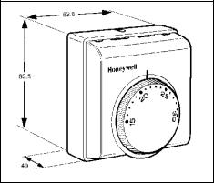
Dimensions:
Protection Class:
Approvals:
Sensors:
24 Vac nominal 50/60Hz, operating range 18 – 30 Vac 1.2 VA nominal (electronics only)
0.3 A (maximum) for all outputs at 24 Vac, with solid state switching 15 to 30 °C
Made via a bank of 6 on-board dip switches 3 different Control Modes :-
Modulating : 3-position modulating P+I control, based on adjustable proportional Band (Xp), and 150sec valve run-time
On/Off |
: Primary stage control is P+I on/off output based on adjustable |
|
Proportional Band (Xp) and a fixed cycle rate (6 cycles/hour Cooling, 6 |
|
cycles/hour heating) |
:Secondary stage control is P+I on/off output based on a fixed Proportional Band of 1K and a fixed cycle rate (6 cycles/hour Cooling, 12 cycles/hour heating)
TPM : Special on/off control mode for thermo-electric actuators 6 different Applications System types :-
•Heat / Cool Changeover
•Cooling Only
•Cooling + optional 2-stage On/off Heating
•Heating Only
•Heating + optional 2-stage On/off Cooling
•Heating + Cooling Sequence Control
1K, 2K, or 4K (depending on system) selected using DIP switches 1K for secondary 2-stage Heating or Cooling stage control
2K or 4K selected using DIP switches
Fixed at 1K, for Systems with secondary 2-stage Heating or Cooling
±0.5K at 20°C
Operating range 0 to 40 °C -20 to 55 °C
10 to 90%, non condensing
±5K by remote unit, resistance input (Q979B1029, Q979C1036)
2 to 8K setup/setback possible, by means of external contact closure input Value set by potentiometer on T8078C
Contact closure can be local or central, to control a group of T8078C (up to 50 max) Automatic changeover by means of external contact closure input
Input can be local (from aquastat) or central from switch/relay (controls up to 50 max) Directly onto wall or wall-box (65x65mm junction box with 60mm screw pitch) or inside terminal unit or fan-coil
Also mounts on fan speed subbase Q6360A1025
Mounting accessory F42007789 available for other mounting configurations 14 x screw terminals capable of accepting up to 1.5mm² stranded cable Max length of wiring to actuators is 100m @ 1.0mm², 150m @ 1.5mm² Flame retardant plastic housing
83.5 x 83.5 x 40 mm IP30 (IEC144)
CE mark, conforming as follows :
Directive (Amendments) 73/23/EEC (93/68/EEC)
89/336/EEC (93/68/EEC & 92/51/EEC)
On-board sensor , type NTC100K
Remote sensor T8109C1002 (1.5m cable) auto detected on power-up Maximum sensor extension is 20m (using screened cable)
3 |
EN0R8535 R1 2003 |
PRODUCT APPLICATIONS
Basic Application |
Controlled Device |
Control Mode – details of application |
Application No. |
2-pipe fan-coil |
Valve control |
Modulating cooling |
1 |
|
“ |
Modulating heating |
2 |
|
“ |
On/off cooling |
7 |
|
“ |
On/off heating |
8 |
|
“ |
TPM cooling (thermo-electric actuator) |
13 |
|
“ |
TPM heating (thermo-electric actuator) |
14 |
|
Airside control (damper) |
Modulating cooling |
1 |
|
“ |
Modulating heating |
2 |
Terminal unit |
Damper control |
Modulating cooling |
1 |
|
“ |
Modulating heating |
2 |
2-pipe fan-coil with auxillary electric heat |
Valve control |
Modulating cooling + 1or 2-stage on/off heating |
3 |
(1 or 2-stage electric heating elements) |
“ |
On/off cooling + 1or 2-stage on/off heating |
9 |
|
“ |
TPM cooling + 1or 2-stage on/off heating |
15 |
|
Airside control (damper) |
Modulating cooling + 1or 2-stage on/off heating |
3 |
2-pipe fan-coil with auxillary cooling |
Valve control |
Modulating heating + 1or 2-stage on/off cooling |
4 |
(1 or 2-stage chillers) |
“ |
On/off heating+ 1or 2-stage on/off cooling |
10 |
|
“ |
TPM heating + 1or 2-stage on/off cooling |
16 |
|
Airside control (damper) |
Modulating heating + 1or 2-stage on/off cooling |
4 |
2-pipe fan-coil with heat/cool changeover |
Valve control |
Modulating heat/cool changeover |
5 |
|
“ |
On/off heat/cool changeover |
11 |
|
“ |
TPM (thermo-electric actuator) heat/cool |
17 |
|
|
changeover |
|
4-pipe fan-coil |
Valve control |
Modulating cooling + heating in sequence |
6 |
|
“ |
On/off cooling + heating in sequence |
12 |
|
“ |
TPM cooling + heating in sequence |
18 |
|
Airside control (damper) |
Modulating cooling + heating in sequence |
1 or 2 |
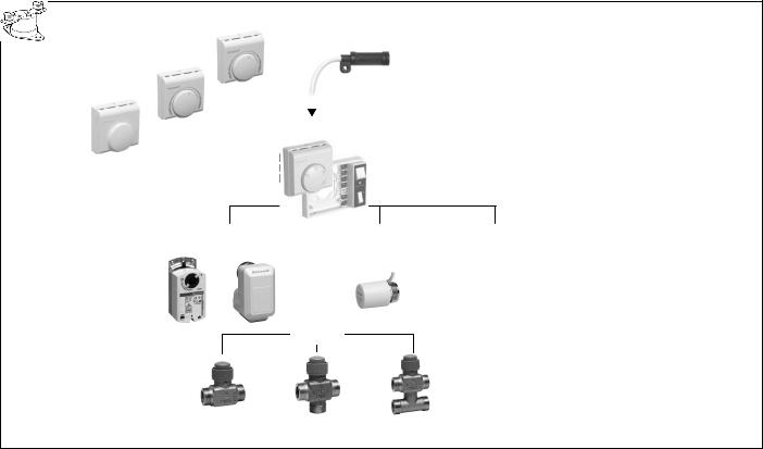
SYSTEM ARCHITECTURE
A diagram of compatible T8078B system components is shown below.
Q979C1036 REMOTE SETPOINT + SENSOR
Q979B1029 |
|
|
|
|
|
|
|
ENERGY SAVINGS INPUT |
||||||
|
|
|
|
|
|
|||||||||
|
|
|
|
|
|
|
HEAT/COOL CHANGEOVER |
|||||||
REMOTE SETPOINT |
|
|
|
|
|
|
|
|||||||
|
|
T8109C1002 |
|
|
|
|
|
|
||||||
ADJUST UNIT |
|
|
|
|
|
|
|
S4390A1004 |
||||||
|
|
|
|
|
|
|
SENSOR |
|
|
|
|
|
||
|
|
|
|
|
|
|
|
|
|
|
|
PIPE STAT |
||
Q979A1020 |
|
|
|
|
|
|
|
|
|
|
||||
|
T8078C CONTROLLER |
|
|
|
|
|
|
|||||||
|
|
|
|
|
|
|
||||||||
SPACE TEMP |
|
|
|
|
|
|
|
|||||||
|
|
|
Q6360A1025 SUB-BASE |
|
|
|
|
|
|
|||||
SENSOR |
|
|
|
|
|
|
|
|
|
|||||
|
|
|
|
|
|
|
|
|
|
|
||||
|
|
|
|
|
|
|
|
|
|
|
|
|
|
|
|
|
|
|
|
|
|
|
|
|
|
|
|
|
|
|
|
|
|
|
|
|
|
|
|
|
|
|
|
|
|
|
|
|
|
|
|
|
|
|
|
|
|
|
|
|
MODULATING |
THERMAL |
ON/OFF |
|
|
ACTUATORs |
ACTUATOR |
ACTUATOR |
|
|
|
|
|
|
ML6161 |
|
M100 |
||
ML6174 |
M7410C |
|||
Z100 |
||||
N2024 |
M6410C |
|||
N3424 |
|
M8450 |
||
|
|
|||
VALVES
V5822C |
V5823A |
V5823C |
V5832C |
V5833A |
V5833C |
4 |
EN0R8535 R1 2003 |
OPERATION
Control Modes
T8078C gives a choice of 3 different output control modes, to suit a range of different actuators and system requirements.
Modulating Control
3-position modulating control is a control form that exactly positions the control valve in order to satisfy the cooling or heating demand.
For each valve actuator there are 2 control outputs, one to drive the valve open, and another to drive the valve closed. The controller can send out control pulses to each of these outputs to move the valve to any position between fully closed and 100% open. The required valve position is calculated using a P+I algorithm, with an adjustable Proportional Band (Xp), and valve actuator run-time of 150seconds.
This type of control gives optimum performance over a wide range of conditions.
On/Off Control (with P+I input)
The on/off control form used by T8078C is one where the output is cycled on and off with a fixed cycled period. The on-time is adjusted by a P+I algorithm so the heating or cooling demand is met and the space is controlled to setpoint.
The cycle rate is 6cycles/hour for cooling and heating.
For the primary control stage, the Proportional Band (Xp) can be selected to be either 1, 2, or 4K, depending on the system.
For the secondary control stages, the Proportional Band is fixed at 1K and the cycle rate is 6cycles/hour for cooling, 12cycles/hour for heating.
This type of on/off control ensures closer control to setpoint than conventional on/off control based on a temperature differential.
TPM Control (for Thermo-Electric Actuators)
Thermo-electric (or thermal) actuators are very cost effective devices, but they present particular difficulties to control because of the time-lags in their response to control inputs. Therefore T8078C uses a special Thermal Predictive Modulating (TPM) control to operate thermal actuators in the optimum way.
This type of on/off control ensures closer control performance when using thermal actuators than conventional on/off control or pulse-width modulating control.
Operating Modes
T8078C has 2 main operating modes, Comfort Mode and
Energy Savings Mode, and also has a Startup / Commissioning Mode which is entered immediately on power-up.
Comfort Mode
This is the normal operating mode, where T8078C controls to the setpoint selected by the user.
Energy Savings Mode
T8078C has an Energy Management System, where the detection of an external input signal will cause the cooling and heating setpoints to change to pre-defined setup and setback temperatures, enabling maximum energy efficiency. This input signal must be in the form of a contact closure, connected to terminals 10 and 11.
Energy Savings Mode – continued
In Energy Savings Mode the Setup/Setback values can be set between 2-8K by means of an on-board potentiometer. In cooling only systems (1, 7, 13) the setpoint will be increased (setup) by the set value fixed by the potentiometer. In heating only systems (2, 8, 14) the setpoint will be decreased (setback).
In heat/cool changeover systems (5, 11, 17) the heating setpoint will be decreased in heating mode, and the cooling setpoint will be increased in cooling mode.
In cooling + heating systems (any system with a Zero Energy Band) the cooling setpoint will be increased by the set value and the heating setpoint will be decreased by the same amount. The setpoint remains the same, but the effect is to widen the Zero Energy Band.
Energy Savings - From Central Location
A group of T8078C units can be switched to Energy Savings mode using a central switch. A maximum of 50 units can be switched this way, but extreme care must be taken to ensure the polarity of wiring connections is correct.
Each T8078C controller will switch to its own pre-defined setback values, as set by its on-board potentiometer.
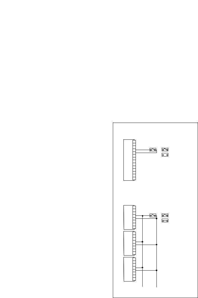
Input Wiring Connections
Single Unit Energy Savings
T8078C 14 |
Switch should be rated 30 Vdc |
|
13 |
||
0.5 mA nominal |
||
12 |
||
= Normal Operation |
||
11 |
10
9  = Energy Savings Mode
8
7
6
5
4
3
2
1
Central Energy Savings
T8078C
Switch should be rated 30 Vdc 0.5 mA nominal
11 |
= Normal Operation |
10
= Energy Savings Mode
T8078C
11
10
T8078C
11
10
x 50 units maximum
Take care to always observe polarity of connection
5 |
EN0R8535 R1 2003 |

Energy Savings Mode - Examples
Startup & Commissioning
On power up, T8078C will immediately undergo a test and synchronisation sequence to enable Installers and Commissioning Engineers to test the system is wired correctly.
Test Sequence
For all control modes, the test sequence will last 60 seconds, and will consist of switching the 4 control outputs on and off in the sequence illustrated. The outputs are connected to terminals 3, 4, 6, and 7.
If it is necessary to repeat the sequence, the power supply can be switched off then back on again.
Valve Synchronisation
The synchronisation sequence will depend on what type of Control Mode has been selected.
For modulating systems, the test sequence will be followed by a 3 minute valve synchronisation, where the valves will be driven to the closed position in order to establish a baseline control reference.
For on/off and TPM control systems, the valve closure sequence will last 10 seconds.
The synchronisation sequence will be repeated 12 hours after power up, and thereafter every 24 hours. This is designed to ensure there will be no disturbance to temperature control during normal hours of building occupancy.
The Diagnostic LED will pulse on and off in the sequence illustrated for Terminal 3 if no faults are detected (see Section entitled ‘Diagnostics & Fault Indication’ for a complete description).
6 |
EN0R8535 R1 2003 |
 Loading...