


T775A,B,C,D
Remote Temperature Controller
PRODUCT DATA
|
|
FEATURES |
|
|
|
||
|
|
• T775A models provide staged on-off control with one |
|
|
|
temperature input and one to four relay output stages. |
|
|
|
• T775B models provide staged on-off control with two |
|
|
|
temperature inputs and two to four relay output stages. |
|
|
|
• T775C models provide staged on-off control with one |
|
|
|
temperature input and four relay output stages. |
|
|
|
• T775D models provide staged on-off control with two |
|
|
|
temperature inputs and four relay output stages. |
|
|
|
• T775C,D models meet National Electrical Code (Article |
|
T775A,B |
|
547) requirements for animal confinement buildings. |
|
T775A,B |
• Setpoint temperature range is -40° to +220°F (-40° to |
||
|
|||
|
+104°C). |
||
|
|
||
|
|
• Ambient temperature range is -30° to +140°F for one |
|
|
|
||
APPLICATION |
|
and two stage models and -30° to +125°F for three and |
|
|
four stage models. |
||
|
• Linear platinum temperature sensor with T775A,B. |
||
|
|
The T775 family of Electronic Remote Temperature Controllers provide on-off temperature control for ducts, tanks, chillers, heating and refrigeration units, and other applications where electronic accuracy in addition to remote sensing is desired.
In addition, certain models of the T775 family of controllers provide on-off temperature control of heating, cooling, and ventilating systems in agricultural confinement buildings, storage areas and heavy industrial applications.
IMPORTANT
The T775 is an operating control, not a limit or safety control. If used in applications requiring safety or limit controls, a separate safety or limit control device should be used in conjunction with the T775.
•Water-tight linear platinum temperature sensor with T775C,D.
•Adjustable temperature range and differential.
•LCD indication for mode and output status.
•Keypad provides ease of programming and operation.
•Accuracy is within +/- 1°F (at nominal operating ambient temperature of 77°F and voltage input).
•Stage(s) independently programmed for heating or cooling.
•24/120/240 Vac input voltage.
•Spdt relay outputs.
|
Contents |
Application ........................................................................ |
1 |
Features ........................................................................... |
1 |
Specifications ................................................................... |
2 |
Ordering Information ........................................................ |
2 |
Installation ........................................................................ |
5 |
Wiring ............................................................................... |
6 |
Checkout .......................................................................... |
10 |
63-2489—2
T775A,B,C,D REMOTE TEMPERATURE CONTROLLER
SPECIFICATIONS
IMPORTANT
Specifications given in this publication do not include normal manufacturing tolerances. Therefore, an individual unit may not exactly match the listed specifications. Also, this product is tested and calibrated under closely controlled conditions
and some minor difference in performance can be expected if those conditions are changed.
Models (see Table 1):
The T775A,B Electronic Temperature Controllers provide staged on-off temperature control for ducts, tanks, chillers, heating and refrigeration units, and other applications where electronic accuracy and remote sensing are desired.
The T775C,D Electronic Remote Temperature Controllers provide staged on-off temperature control of heating, cooling and ventilating systems in agricultural confinement buildings, storage areas, and heavy industrial applications.
Dimensions: See Fig. 1 and 2.
Mounting: Mounts on any suitable horizontal or vertical surface (see Fig. 3 and 4 for mounting hole locations).
Temperature Accuracy: +/-1°F (at nominal voltage in 77°F [25°C] ambient, nominal sensor value). Accuracy may vary based on deviation from nominal values of input voltage, operating ambient and sensor ambient.
Setpoint Adjustment Range: -40° to 220°F (-40° to 104°C).
Display Resolution: Sensed temperature and other operating parameters are displayed via a liquid crystal display (LCD) with a resolution of 1°F or 1°C.
Operating Ambient Temperature:
One and Two Stage units: -30° to 140°F.
Three and Four Stage units: -30° to 125°F.
Operating Humidity:
5% to 95% relative humidity (rh) noncondensing.
Sensor: Positive coefficient platinum type, 4.8 ohms/ °F, 1000 ft maximum distance between sensor and solid state controller (requires calibration over 400 ft). To maintain NEMA 4X rating, use environmental-proof cable and sensor.
Electrical Ratings:
Voltage Input: 24/120/240 Vac, 50/60 Hz (+10%/-15%). Power Consumption:
For one and two stage units: 8 VA maximum at 60 Hz. 10 VA maximum at 50 Hz. For three and four stage units: 13 VA maximum at 60 Hz. 20 VA maximum at 50 Hz.
Table 1. T775 Models.
|
|
Relay |
Maximum Operating |
|
Model |
Inputs |
Outputs |
Ambient Temperature |
Comments |
T775A1001 |
1 |
1 |
140°F (60°C) |
Includes one 193987GA Sensor. |
T775A1019 |
1 |
2 |
140°F (60°C) |
|
|
|
|
|
|
T775A1027 |
1 |
3 |
125°F (52°C) |
|
|
|
|
|
|
T775A1035 |
1 |
4 |
125°F (52°C) |
|
|
|
|
|
|
T775B1000 |
2 |
2 |
140°F (60°C) |
Includes two 193987GA Sensors. |
|
|
|
|
|
T775B1018 |
2 |
3 |
125°F (52°C) |
|
|
|
|
|
|
T775B1026 |
2 |
4 |
125°F (52°C) |
|
|
|
|
|
|
T775C |
1 |
4 |
125°F (52°C) |
NEMA 4X enclosure. Includes one 203401B Remote Sensor. |
|
|
|
|
|
T775D |
2 |
4 |
125°F (52°C) |
NEMA 4X enclosure. Includes two 203401B Remote Sensors. |
|
|
|
|
|
ORDERING INFORMATION
When purchasing replacement and modernization products from your TRADELINE® wholesaler or distributor, refer to the TRADELINE® Catalog or price sheets for complete ordering number.
If you have additional questions, need further information, or would like to comment on our products or services, please write or phone:
1.Your local Honeywell Automation and Control Products Sales Office (check white pages of your phone directory).
2.Honeywell Customer Care 1885 Douglas Drive North
Minneapolis, Minnesota 55422-4386
In Canada—Honeywell Limited/Honeywell Limitée, 35 Dynamic Drive, Scarborough, Ontario M1V 4Z9.
International Sales and Service Offices in all principal cities of the world. Manufacturing in Australia, Canada, Finland, France, Germany, Japan, Mexico, Netherlands, Spain, Taiwan, United Kingdom, U.S.A.
63-2489—2 |
2 |
Contact Ratings:
1/2 hp; 9.8 FLA, 58.8 LRA at 120 Vac. 1/2 hp; 4.9 FLA, 29.4 LRA at 240 Vac. 125 VA pilot duty at 120/240 Vac.
10A at 24 Vac (resistive).
Approvals:
Underwriters Laboratories Inc. Listed: File no. E4436. Canadian Standards Assoc. certified: File no. LR47125.
Accessories:
T775A,B:
A775A1003 Temperature Sensor Simulator. C7100C Duct Mount Averaging Sensor. 198212CA Water Resistant Sensor. 203401B Water Tight Sensor. T7047C1090 Wall Mounted Sensor Case. 107324A Bulb Holder, duct insertion. 121371A Copper Immersion Well. 121371E Stainless Steel Well.
107048 Heat Conduction Compound, 4 ounce. C7043A1098 Case and Immersion Well for running conduit
to sensor. T775C,D:
121371A Copper Immersion Well.
121371E Stainless Steel Well.
107408 Heat Conduction Compound, 4 ounce. C7043A1098 Case and Immersion Well for running conduit
to sensor.
T775A,B,C,D REMOTE TEMPERATURE CONTROLLER
SELECT SET  ENTER
ENTER
8-1/2
(216)
5-7/32
(134)
1-1/4
(32)
3-13/16 (97)
 1-1/4
1-1/4  (32)
(32)
4-3/4 (121) |
2-3/8 (60) |
7/8 (22) DIAMETER |
M344C |
|
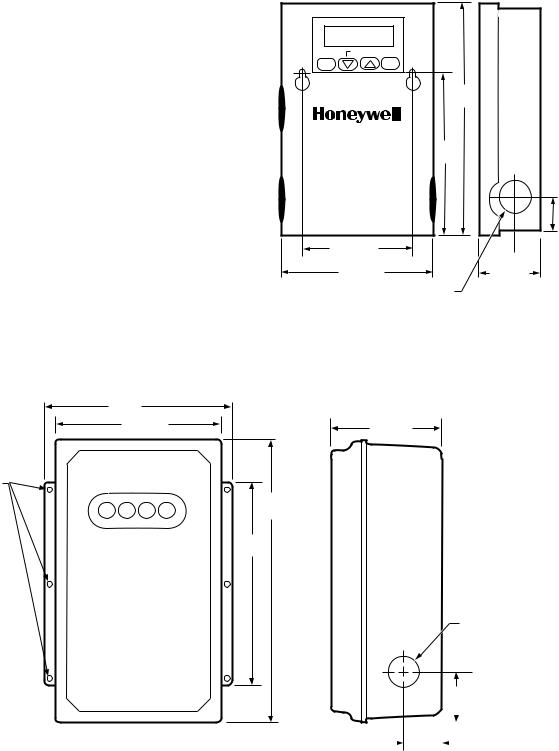
Fig. 1. Approximate dimensions of T775A,B in in. (mm).
6 (153) |
|
5-1/4 (133) |
3-1/2 (89) |
|
|
MOUNTING |
|
HOLES |
|
|
9 |
|
(229) |
|
6-1/2 |
|
(165) |
7/8 (22) DIAMETER
1-1/4
(32)
|
|
|
|
|
|
|
|
|
|
|
|
|
|
|
|
|
|
1-3/8 |
|
|
|
|
M1301B |
|
|
|
|||||
(34) |
|
|
|
|
|
||
Fig. 2. Approximate dimensions of T775C,D in in. (mm)
3 |
63-2489—2 |

T775A,B,C,D REMOTE TEMPERATURE CONTROLLER
LCD TEMPERATURE |
|
|
|
|
|
|
|
|
C \ F |
F/C SELECTION |
DISPLAY |
|
|
|
|
|
|
|
|
||
|
|
|
|
|
|
|
|
|
|
|
|
|
|
|
|
|
|
|
|
1 |
DIP SWITCHES FOR |
|
|
|
|
|
|
|
|
|
3 2 |
|
PROGRAMMING |
|
|
|
|
|
|
|
|
SENSOR SELECTION. |
|
KEYS |
|
|
|
|
|
|
|
|
4 |
PRESENT ON T775B |
|
|
|
|
|
|
|
|
|
||
|
SELECT |
|
|
SET |
|
ENTER |
|
ONLY |
||
|
|
|
|
|
|
|
|
|
SA SB |
|
SENSOR INPUT, |
|
|
|
|
|
|
|
|
|
MOUNTING HOLE |
|
|
|
|
|
|
|
|
|
|
|
TOD, AND 24VAC |
|
|
|
|
|
|
|
|
|
LOCATION |
|
|
|
|
|
|
|
|
|
|
|
TERMINALS |
|
|
|
|
|
|
|
|
|
|
HOLE A |
1 |
2 |
3 |
4 |
5 |
6 |
7 |
8 |
|
|
|
|
|
|
|
|
|
|
|
|
|
|
SENSOR |
TOD |
|
24V SENSOR |
|
|
||||
|
A |
|
|
|
|
B |
|
|
|
|
|
OUTPUT 2 |
|
|
|
|
OUTPUT 1 |
|
LINE VOLTAGE |
||
|
|
|
|
|
|
INPUTS |
||||
|
NC |
|
|
|
|
|
|
NC |
120V |
|
|
|
|
|
|
|
|
|
|||
|
COM |
|
|
|
|
|
|
COM |
COM |
|
|
NO |
|
|
|
|
|
|
NO |
240V |
|
KNOCKOUT B |
|
NO |
|
|
|
|
|
NO |
|
KNOCKOUT C |
|
|
|
|
|
|
|
|
|
|
|
|
COM |
|
|
|
|
|
COM |
|
||
|
|
|
|
|
|
|
|
|
||
|
|
NC |
|
|
|
|
|
NC |
|
|
|
|
|
|
|
|
|
|
|
|
|
|
OUTPUT 3 |
|
|
|
OUTPUT 4 |
|
||||
RELAY OUTPUT STAGES |
NOTE: T775A TERMINAL BLOCK CONTAINS ONLY |
|
(MAXIMUM OF FOUR STAGES) |
TERMINALS 1-6 AND HAS NO DIP SWITCHES |
|
|
FOR SENSOR SELECTION |
M7423 |
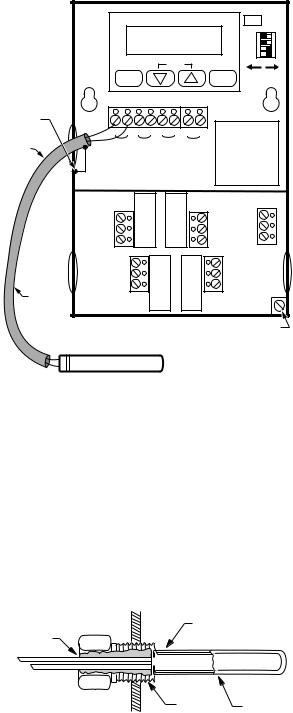
Fig. 3. Feature locations for T775A,B.
LCD TEMPERATURE DISPLAY
PROGRAMMING
KEYS
SENSOR INPUT,
TOD, AND 24VAC
TERMINALS
|
|
C \ F |
|
|
4 3 2 1 |
SELECT |
SET |
ENTER |
|
|
SA SB |
F/C SELECTION
DIP SWITCHES FOR SENSOR SELECTION. PRESENT ON T775D ONLY
HOLE A |
1 |
2 |
3 |
4 |
5 |
6 |
7 |
8 |
|
|
|
|
|
|
|
|
|
|
|
|
|
|
SENSOR TOD |
|
24V |
SENSOR |
|
MOUNTING |
||||
|
|
A |
|
|
|
|
|
B |
|
|
|
|
|
|
|
|
|
|
|
|
HOLES |
EARTH |
|
|
|
|
|
|
|
|
|
|
GROUND |
|
|
|
|
|
|
|
|
|
|
WIRE |
OUTPUT 2 |
|
|
|
|
OUTPUT 1 |
|
|
||
|
|
|
|
|
|
|
||||
|
NC |
|
|
|
|
|
|
NC |
120V |
|
|
COM |
|
|
|
|
|
|
COM |
COM |
|
|
NO |
|
|
|
|
|
|
NO |
240V |
|
HOLE B |
|
NO |
|
|
|
|
|
NO |
|
|
|
|
|
|
|
|
|
|
|
|
|
|
COM |
|
|
|
|
|
COM |
LINE VOLTAGE |
||
|
|
|
|
|
|
|
|
|||
|
|
|
|
|
|
|
|
NC |
|
|
|
|
NC |
|
|
|
|
|
|
INPUTS |
|
|
|
|
|
|
|
|
|
|
||
|
OUTPUT 3 |
|
|
|
OUTPUT 4 |
HOLE C |
||||
RELAY OUTPUT STAGES |
|
|
|
|
|
|
NOTE: T775C TERMINAL BLOCK CONTAINS ONLY |
|||
|
|
|
|
|
|
TERMINALS 1-6 AND HAS NO DIP SWITCHES |
||||
|
|
|
|
|
|
|
|
|||
|
|
|
|
|
|
|
|
FOR SENSOR SELECTION |
M7427 |
|
Fig. 4. Feature locations for T775C,D.
63-2489—2 |
4 |
INSTALLATION
When Installing this Product...
1.Read these instructions carefully. Failure to follow them could damage the product or cause a hazardous condition.
2.Check ratings given in instructions and on the product to ensure the product is suitable for your application.
3.Installer must be a trained, experienced service technician.
4.After installation is complete, check out product operation as provided in these instructions.
 CAUTION
Electrical Shock or Equipment Damage Hazard. Can shock individuals or short equipment circuitry.
Disconnect power supply before installation.
Location and Mounting
Mount the controller on any convenient interior location using the two mounting holes provided on the back of the metal enclosure (mounting screws are not provided and must be obtained separately). Use controller dimensions in Fig. 1 (T775A,B) or Fig. 2 (T775C,D) as a guide.
Sensor Location
The 193987GA Sensor can be located up to 1000 feet (304m) from the T775 using standard AWG 18/2 unshielded wire. For cable runs greater than 25 feet shielded cable is recommended. See Fig. 5. It may be located on pipes, in an immersion well, in a wall-mounted case or on a bulb holder. See Fig. 7. The 193987GA is not a water tight or water resistant sensor. For wet applications, see the Accessories list in the Specifications section.
Multiple sensors can be parallel-series wired to sense average temperatures in large spaces.
To maintain control accuracy, the number of sensors parallelseries wired must be of the n2 power (for example, 4, 9, 16, etc.). See Fig. 8.
Sensor Mounting
Sensors can be mounted on a wall or panel for sensing space temperature (Fig. 7), strapped to a pipe or inserted in a well (Fig. 6) for hot/cold water sensing, or taped to a standard cap or bulb holder for duct air sensing. To prevent moisture or condensation entering the sensor through the leadwire holes, mount the sensor with the lead wires exiting the bottom of the sensor.
T775A,B,C,D REMOTE TEMPERATURE CONTROLLER
T775
|
|
|
|
|
|
|
|
|
C \ F |
|
|
|
|
|
|
|
|
|
4 3 2 1 |
|
SELECT |
|
|
SET |
|
ENTER |
|
||
GROUND |
|
|
|
|
|
|
|
|
SA SB |
SHIELD |
|
|
|
|
|
|
|
|
|
|
|
|
|
|
|
|
|
|
|
TO T775 |
|
|
|
|
|
|
|
|
|
CABLE OR TO |
|
|
|
|
|
|
|
|
|
GROUNDING |
|
|
|
|
|
|
|
|
|
SCREW |
|
|
|
|
|
|
|
|
|
|
1 |
2 |
3 |
4 |
5 |
6 |
7 |
8 |
|
SHIELDED |
SENSOR |
TOD |
|
24V SENSOR |
|
||||
CABLE |
|
|
|||||||
A |
|
|
|
|
B |
|
|
|
|
|
|
|
|
|
|
|
|
||
|
OUTPUT 2 |
|
|
|
|
OUTPUT 1 |
|
||
|
NC |
|
|
|
|
|
|
NC |
120V |
|
COM |
|
|
|
|
|
|
COM |
COM |
|
NO |
|
|
|
|
|
|
NO |
240V |
|
|
NO |
|
|
|
|
|
NO |
|
|
|
|
|
|
|
|
|
|
|
|
COM |
|
|
|
|
|
COM |
||
|
|
|
|
|
|
|
|
||
|
|
NC |
|
|
|
|
|
NC |
|
|
|
|
|
|
|
|
|
|
|
SHIELDED |
OUTPUT 3 |
|
|
|
OUTPUT 4 |
||||
CABLE |
|
|
|
|
|
|
|
|
|
NOTE: DO NOT GROUND |
|
|
|
|
|
GROUNDING SCREW |
|||
SHIELDED CABLE AT |
|
|
|
|
|
|
|
||
SENSOR END. |
|
|
SENSOR |
|
|
|
|||
NOTE: TO MINIMIZE NOISE PICKUP, MAKE CONNECTION
FROM SHIELDED CABLE AS CLOSE AS POSSIBLE
M7430
TO SENSOR BODY.
Fig. 5. Using shielded cable (cable runs longer than 25 ft).
NOTE: Use heat conductive compound in immersion wells. See Accessories in the Specifications section.
 CAUTION
Electrical Shock Hazard.
Can short equipment circuitry.
Make sure that metal tube of sensor does not short against T terminals in wall-mounted case.
COVER SENSOR |
|
|
LEADS WITH |
SENSOR PLACED |
|
HEAT CONDUCTIVE |
||
IN WELL |
||
COMPOUND |
||
|
1/2 NPT |
IMMERSION |
|
WELL |
|
M5249 |
Fig. 6. Sensor inserted in immersion well.
5 |
63-2489—2 |
 Loading...