


ST 3000 Smart Transmitter |
|
34-ST-03-57 |
|
||
|
10/2002 |
|
|||
Series 900 Remote Diaphragm Seals Models |
|
Specification and |
|
||
STR93D |
0 to 100 psid |
0 to 7 bar |
|
|
|
|
Model Selection |
|
|||
STR94G |
0 to 500 psig |
0 to 35 bar |
|
|
|
|
|
|
|
Guide |
|
|
|
|
|
|
|
Introduction
In 1983, Honeywell introduced the first Smart Pressure Transmitter― the ST 3000®. In 1989, Honeywell launched the first all digital, bi-directional protocol for smart field devices. Today, its
ST 3000 Series 900 Remote Seal Transmitters continue to bring proven “smart” technology to a wide spectrum of pressure measurement applications. For applications in which the transmitter must be mounted remotely from the process, Honeywell offers the remote seal line of gauge, absolute and differential pressure transmitters. Typical applications include level measurement in pressurized vessels in the chemical and hydrocarbon processing industries. A second application is flow measurement for slurries and high viscosity fluids in the chemical industry. Honeywell remote seal transmitters are available with secondary fill fluids for corrosive or high temperature process fluids
All ST 3000 transmitters can provide a 4-20 mA output, Honeywell Digitally Enhanced (DE) output, HART* output, or FOUNDATION™ Fieldbus output. When digitally integrated with Honeywell’s Process Knowledge System™, EXPERION PKS™,
ST 3000 instruments provide a more accurate process variable as well as advanced diagnostics.
Honeywell’s cost-effective ST 3000 S900 transmitters lead the industry in reliability and stability:
•Stability = +/-0.01% per year
•Reliability = 470 years MTBF
Figure 1—Series 900 Remote Seal Pressure Transmitters feature proven piezoresistive sensor technology.
The devices provide comprehensive self-diagnostics to help users maintain high uptime, meet regulatory requirements, and attain high quality standards. S900 transmitters allow smart performance at analog prices. Accurate, reliable and stable, Series 900 transmitters offer greater turndown ratio than conventional transmitters.
"Honeywell transmitters operating in the digital mode using Honeywell's Digitally Enhanced (DE) protocol make diagnostics available right at the control system's human interface. Equally important, transmitter status information is continuously displayed to alert the operator immediately of a fault condition. Because the process variable (PV) status transmission precedes the PV value, we are guaranteed that a bad PV is not used in a control algorithm. In addition, bi-directional communication provides for remote transmitter configuration directly from the human interface, enabling management of the complete loop.”
Maureen Atchison, DuPont
Site Electrical & Instrumentation Leader

34-ST-03-57
Page 2
Description
The ST 3000 transmitter can replace any 4 to 20 mA output transmitter in use today and operates over a standard two-wire system.
The measuring means is a piezoresistive sensor, which actually contains three sensors in one. It contains a differential pressure sensor, a temperature sensor, and a static pressure sensor.
Microprocessor-based electronics provide higher span-turndown ratio, improved temperature and pressure compensation, and improved accuracy.
The transmitter’s meter body and electronics housing resist shock, vibration, corrosion, and moisture. The electronics housing contains a compartment for the single-board electronics, which is isolated from an integral junction box. The single-board electronics is replaceable and interchangeable with any other ST 3000 Series 100 or Series 900 model transmitter.
Like other Honeywell transmitters, the ST 3000 features two-way communication between the operator and the transmitter through our Smart Field Configurator (SFC). You can connect the SFC anywhere that you can access the transmitter signal lines.
The SCT 3000 Smartline® Configuration Toolkit provides an easy way to configure instruments using a personal computer. The toolkit enables configuration of devices before shipping or installation. The SCT 3000 can operate in the offline mode to configure an unlimited number of devices. The database can then be loaded downline during commissioning.
Features
•Choice of linear or square root output conformity is a simple configuration selection.
•Direct digital integration with Experion PKS and other control systems provides local measurement accuracy to the system level without adding typical A/D and D/A converter inaccuracies.
•Unique piezoresistive sensor automatically compensates input for temperature and static pressure.Added “smart” features include configuring lower and upper range values, simulating accurate analog output, and selecting preprogrammed engineering units for display.
•Smart transmitter capabilities with local or remote interfacing means significant manpower efficiency improvements in commissioning, start-up, and ongoing maintenance functions.
|
|
|
|
|
|
|
|
|
|
|
|
|
|
34-ST-03-57 |
||
|
|
|
|
|
|
|
|
|
|
|
|
|
|
|
Page 3 |
|
|
|
|
|
|
|
|
|
|
|
|
|
|
|
|
|
|
|
|
|
|
|
|
|
Specifications |
|
|
|
|
|
|
|
||
|
Operating Conditions – All Models |
|
|
|
|
|
|
|
|
|
|
|||||
|
Parameter |
Reference |
|
Rated Condition |
Operative Limits |
Transportation |
|
|||||||||
|
|
|
Condition |
|
|
|
|
|
|
|
and Storage |
|
||||
|
|
|
(at zero |
|
|
|
|
|
|
|
|
|
|
|
||
|
|
|
static) |
|
|
|
|
|
|
|
|
|
|
|
||
|
|
|
°C |
|
°F |
|
°C |
|
°F |
°C |
|
°F |
°C |
|
°F |
|
|
|
|
|
|
|
|
|
|
|
|
|
|
|
|
||
|
Ambient Temperature |
25 ±1 |
|
77 ±2 |
|
-25 to 70 |
|
-13 to 158 |
-40 to 85 |
|
-40 to 185 |
-55 to 125 |
-67 to 257 |
|
||
|
Process Interface |
|
25 ±1 |
|
77 ±2 |
|
|
|
See Figure 2 |
|
|
-55 to 125 |
-67 to 257 |
|
||
|
Temperature |
|
|
|
|
|
|
|
|
|
|
|
|
|
|
|
|
Humidity |
%RH |
10 to 55 |
|
0 to 100 |
0 to 100 |
|
0 to 100 |
|
|||||||
|
Overpressure (Flange |
|
|
|
|
|
|
|
|
|
|
|
|
|
|
|
|
Rating) |
psi |
|
0 |
|
|
750* |
750* |
|
|
|
|
||||
|
|
bar |
|
0 |
|
|
52* |
|
52* |
|
|
|
|
|||
|
|
|
|
|
|
|
|
|
|
|
|
|
|
|
|
|
|
Vacuum Region, |
Minimum |
|
|
|
|
|
|
|
|
|
|
|
|
|
|
|
Pressure - mmHg absolute |
atmospheric |
|
|
|
See Figure 2 |
|
|
|
|
|
|
||||
|
inH2O absolute |
atmospheric |
|
|
|
|
|
|
|
|
|
|
|
|||
|
Supply Voltage, Current, |
Voltage Range: |
10.8 to 42.4 Vdc at terminals |
|
|
|
|
|
|
|||||||
|
and Load Resistance |
Current Range: |
3.0 to 21.8 mA |
|
|
|
|
|
|
|
||||||
|
|
|
Load Resistance: 0 to 1440 ohms (as shown in Figure 3) |
|
|
|
|
|||||||||
* Or Seal rating, whichever is lower. See Model Selection Guide for Seal rating.

34-ST-03-57
Page 4
Maximum Pressure Limited |
|
|
|
|
|
|
|
|
|
by Flange Rating of Seal |
|
|
|
|
|
|
|
|
|
10000 |
|
|
|
|
|
|
|
|
193 |
9000 |
|
|
|
|
|
|
|
|
psig |
8000 |
|
|
|
|
|
|
|
|
|
7000 |
|
|
|
Silicone DC704 |
|
|
|
|
|
6000 |
|
|
|
|
|
|
|
||
5000 |
|
|
|
|
30 to 450°F |
|
|
|
|
4000 |
|
|
|
|
|
|
|
|
|
3000 |
|
|
|
|
|
|
|
|
|
2000 |
|
|
|
Silicone DC200 |
|
|
|
|
|
|
|
|
|
-40 to 350°F |
|
|
|
|
|
|
|
|
|
|
|
|
|
|
|
1000 |
|
|
|
|
|
|
|
|
|
900 |
|
|
|
|
|
|
|
|
1Atm |
800 |
|
|
|
|
|
|
|
|
|
700 |
|
|
|
|
CTFE |
|
|
|
0 |
600 |
|
|
|
|
|
|
|
psig |
|
500 |
|
|
|
|
|
|
|
||
400 |
|
|
|
|
5 to 300°F |
|
|
|
-9 |
300 |
|
|
|
|
|
|
|
|
|
|
|
|
|
|
|
|
|
psig |
|
200 |
|
|
|
|
|
|
|
|
|
|
|
|
|
|
|
|
|
|
|
100 90 |
|
|
|
|
|
|
|
|
|
80 |
|
|
|
|
|
|
Special High Vacuum |
|
|
70 |
|
|
|
|
|
|
|
||
60 |
|
|
|
|
|
|
Construction required. |
|
|
50 |
|
|
|
|
|
|
|
||
40 |
|
|
|
|
|
|
Consult STC. |
|
|
30 |
|
|
|
|
|
|
|
|
|
Pressure20 |
|
|
|
|
|
|
|
|
|
(mmHgA) |
|
|
|
|
|
|
|
|
-14 |
10 |
|
|
|
|
|
|
|
|
|
|
|
|
|
|
|
|
450 |
psig |
|
-40 |
5 |
25 |
30 |
|
175 |
|
350 |
||
100 |
|
500 |
|||||||
-100 |
0 |
|
|
200 |
300 |
400 |
|
||
Maximum Pressure Limited |
|
|
|
Process Temperature (Degrees F) |
|
|
|
||
|
|
|
|
|
|
|
|
|
|
by Flange Rating of Seal |
|
|
|
|
|
|
|
|
|
10000 |
|
|
|
|
|
|
|
|
193 |
9000 |
|
|
|
|
|
|
|
|
psig |
8000 |
|
|
|
|
|
|
Syltherm 800 |
|
|
7000 |
|
|
|
|
|
|
|
|
|
6000 |
|
|
|
|
|
|
-40 to 600°F |
|
90 |
5000 |
|
|
|
|
|
|
|
||
|
|
|
|
|
|
|
|
psig |
|
4000 |
|
|
|
|
|
|
|
|
|
|
|
|
|
|
|
|
|
|
|
3000 |
|
|
|
|
NEOBEE M-20 |
|
|
|
|
2000 |
|
|
|
|
30 to 400°F |
|
|
|
|
|
|
|
|
|
|
|
|
|
|
1000900 |
|
|
|
|
|
|
|
|
1Atm |
800 |
|
|
|
|
|
|
|
|
|
700 |
|
|
|
|
|
|
|
|
0 |
600 |
|
|
|
|
|
|
|
|
psig |
500 |
|
|
|
|
|
|
|
|
|
|
|
|
|
|
|
|
|
|
|
400 |
|
|
|
|
|
|
|
|
|
300 |
|
|
|
|
|
|
|
|
-9 |
200 |
|
|
|
|
|
|
|
|
psig |
|
|
|
|
|
|
|
|
|
|
100 90 |
|
|
|
|
|
|
|
|
|
80 |
|
|
|
|
|
|
|
|
|
70 |
|
|
|
|
|
|
|
|
|
60 |
|
|
|
|
|
|
|
|
|
50 |
|
|
|
|
|
|
|
|
|
40 |
|
|
|
|
|
|
|
|
|
30 |
|
|
|
|
|
|
|
|
|
Pressure20 |
|
|
|
|
|
|
|
|
|
(mmHgA) |
|
|
|
|
|
|
|
|
-14 |
10 |
|
|
|
|
|
|
|
|
|
|
|
|
|
|
|
|
550 |
psig |
|
-40 |
5 |
25 |
30 |
|
175 |
|
450 |
||
100 |
|
600 |
|||||||
-100 |
0 |
|
|
200 |
400 |
500 |
|
||
Process Temperature (Degrees F) |
20335 |
Figure 2—ST 3000 Remote Seals operable limits for pressure versus temperature

34-ST-03-57
Page 5
|
1440 |
|
|
|
|
|
|
1200 |
|
|
|
|
|
Loop |
800 |
|
|
|
|
|
Resistance |
|
|
|
|
|
|
|
|
|
|
|
|
|
(ohms) |
650 |
|
|
|
|
|
|
|
|
|
|
|
|
|
450 |
|
|
|
|
|
|
250 |
|
|
|
|
|
|
0 |
10.8 |
16.28 20.63 25 |
28.3 |
37.0 |
42.4 |
=Operating Area
NOTE: A minimum of 250 0hms of loop resistance is necessary to support communications. Loop resistance equals barrier resistance plus wire resistance plus receiver resistance. Also 45 volt operation is permitted if not an intrinsically safe installation.
Operating Voltage (Vdc) |
21012 |
Figure 3—Supply voltage and loop resistance chart
Performance Under Rated Conditions * - Model STR93D (0 to 100 psi/7 bar)
Parameter |
|
|
|
|
|
|
|
|
Description |
|
|
|||||||
|
|
|
|
|
|
|
|
|
|
|
|
|
|
|||||
Upper Range Limit |
psi |
100 (Transmitter URL or maximum seal pressure rating, whichever is lower.) |
||||||||||||||||
|
bar |
7 |
|
|
|
|
|
|
|
|
|
|
|
|
|
|
|
|
Minimum Span |
psi |
0.9 |
|
|
|
|
|
|
|
|
|
|
|
|
|
|
|
|
|
bar |
0.063 |
|
|
|
|
|
|
|
|
|
|
|
|
|
|
|
|
Turndown Ratio |
|
110 to 1 |
|
|
|
|
|
|
|
|
|
|
|
|
|
|
|
|
|
|
|
|
|
|
|
|
|
|
|
|
|
|
|||||
Zero Elevation and Suppression |
No limit except minimum span within ±100% URL. |
|
|
|||||||||||||||
|
|
|
|
|
|
|
|
|||||||||||
Accuracy (Reference – Includes |
In Analog Mode: ±0.20% of calibrated span or upper range value (URV), whichever is |
|||||||||||||||||
combined effects of linearity, |
|
greater, terminal based. |
|
|
|
|
|
|
|
|
|
|||||||
hysteresis, and repeatability) |
|
For URV below reference point (50 inH2O), accuracy equals: |
|
|||||||||||||||
• Accuracy includes residual error |
±0.10 + 0.10 |
50 inH2O |
or ±0.10 + 0.10 |
|
|
125 mbar |
|
in % span |
||||||||||
after averaging successive |
|
|
|
|
||||||||||||||
|
|
|
|
|
|
|
|
|
|
|
|
|||||||
|
span inH2O |
(span mbar) |
||||||||||||||||
readings. |
|
|
|
|
|
|
||||||||||||
• For FOUNDATION Fieldbus use |
In Digital Mode: ±0.175% of calibrated span or upper range value (URV), whichever |
|||||||||||||||||
is greater, terminal based. |
|
|
|
|
|
|
|
|
|
|||||||||
Digital Mode specifications. For |
|
|
|
|
|
|
|
|
|
|||||||||
For URV below reference point (50 inH2O), accuracy equals: |
|
|||||||||||||||||
HART use Analog Mode |
|
|
||||||||||||||||
specifications. |
|
|
|
|
50 inH2O |
|
|
|
|
( |
125 mbar |
) in % span |
||||||
|
|
±0.075 + 0.10 |
|
|
|
or ±0.075 + 0.10 |
|
|
|
|||||||||
|
|
span inH2O |
span mbar |
|||||||||||||||
Combined Zero and Span |
|
In Analog Mode: ±1.5% of span. |
|
|
|
|
|
|
|
|
||||||||
Temperature Effect per 28°C |
For URV below reference point (100 inH2O), effect equals: |
|
|
|||||||||||||||
(50°F) ** |
|
|
100 inH2O |
|
|
250 mbar |
|
|
||||||||||
• Specification doubles for 2-inch |
±0.30 + 1.2 |
or ±0.30 + 1.2 |
|
in % span |
||||||||||||||
|
|
|
|
|
|
|
|
|
|
|
|
|||||||
span inH2O |
(span mbar) |
|||||||||||||||||
Sanitary Seals or for model with |
|
|
|
|
||||||||||||||
only one remote seal |
|
In Digital Mode: ±1.475% of span. |
|
|
|
|
|
|
|
|
||||||||
|
|
For URV below reference point (100 inH2O), effect equals: |
|
|
||||||||||||||
|
|
|
|
100 inH2O |
|
|
|
|
250 mbar |
|
|
|||||||
|
|
±0.275 + 1.2 |
|
|
|
or ±0.275 + 1.2 ( |
|
) in % span |
||||||||||
|
|
span inH2O |
span mbar |
|||||||||||||||
*Performance specifications are based on reference conditions of 25°C (77°F), zero (0) static pressure, 10 to 55% RH, and 316L Stainless Steel barrier diaphragm.
**Apply 1.5 times factor to capillary lengths greater than 10 feet.
34-ST-03-57
Page 6
Performance Under Rated Conditions * - Models STR94G (0 to 500 psi/35 bar)
Parameter |
|
|
|
|
|
Description |
|||||
|
|
|
|
|
|
|
|
|
|
|
|
Upper Range Limit |
psi |
500 |
|
|
|
|
|
|
|
|
|
|
bar |
35 |
|
|
|
|
|
|
|
|
|
Minimum Span |
psi |
20 |
|
|
|
|
|
|
|
|
|
|
bar |
1.4 |
|
|
|
|
|
|
|
|
|
Turndown Ratio |
|
25 to 1 |
|
|
|
|
|
||||
|
|
|
|
|
|
|
|
|
|
||
Zero Elevation and Suppression |
No limit except minimum span from absolute 0 (zero) to +100% URL. |
||||||||||
|
|
|
|
|
|
|
|
|
|
||
Accuracy (Reference – Includes |
In Analog Mode: ±0.10% of calibrated span or upper range value (URV), whichever is |
||||||||||
combined effects of linearity, |
|
greater, terminal based. |
|
|
|
|
|
||||
hysteresis, and repeatability) |
|
In Digital Mode: ±0.075% of calibrated span or upper range value (URV), whichever |
|||||||||
|
|
||||||||||
• Accuracy includes residual error |
is greater, terminal based. |
|
|
|
|
|
|||||
after averaging successive |
|
|
|
|
|
|
|
|
|
|
|
readings. |
|
|
|
|
|
|
|
|
|
|
|
• For FOUNDATION Fieldbus use |
|
|
|
|
|
|
|
|
|
|
|
Digital Mode specifications. For |
|
|
|
|
|
|
|
|
|
|
|
HART use Analog Mode |
|
|
|
|
|
|
|
|
|
|
|
specifications. |
|
|
|
|
|
|
|
|
|
|
|
|
|
|
|
|
|
|
|
||||
Combined Zero and Span |
|
In Analog Mode: ±2.2% of span. |
|
|
|
|
|
||||
Temperature Effect per 28°C |
For URV below reference point (50 psi), effect equals: |
||||||||||
(50°F) ** |
|
|
50 psi |
|
3.5 bar |
||||||
|
|
|
|
||||||||
|
|
±0.2 + 2.0 ( |
|
|
) or ±0.2 + 2.0 |
( |
|
|
) in % span |
||
|
|
span psi |
span bar |
||||||||
|
|
In Digital Mode: ±2.175% of span |
|
|
|
|
|
||||
|
|
For URV below reference point (50 psi), effect equals: |
|||||||||
|
|
|
|
50 psi |
|
|
3.5 bar |
||||
|
|
±0.175 + 2.0 ( |
|
) or ±0.175 + 2.0 ( |
|
) in % span |
|||||
|
|
span psi |
span bar |
||||||||
*Performance specifications are based on reference conditions of 25°C (77°F), zero (0) static pressure, 10 to 55% RH, and 316L Stainless Steel barrier diaphragm.
**Apply 1.5 times factor to capillary lengths greater than 10 feet.
Performance Under Rated Conditions - General for all Models
Parameter |
Description |
|
|
Output (two-wire) |
Analog 4 to 20 mA or DE digital communications mode. Options available for |
|
FOUNDATION Fieldbus and HART protocols. |
|
|
Supply Voltage Effect |
0.005% span per volt. |
|
|
Damping Time Constant |
Adjustable from 0 to 32 seconds digital damping. |
|
|
CE Conformity (Europe) |
89/336/EEC, Electromagnetic Compatibility (EMC) Directive. |
|
|
|
|
34-ST-03-57 |
|
|
|
Page 7 |
|
Physical and Approval Bodies |
|
||
Parameter |
Description |
||
|
|
||
Process Interface |
See Model Selection Guide for Material Options for desired Seal Type. |
||
|
|
||
Seal Barrier Diaphragm |
316L Stainless Steel, Monel, Hastelloy C, Tantalum |
||
|
|
|
|
Seal Gasket Materials |
Klinger C-4401 (non-asbestos) |
|
|
|
Grafoil |
|
|
|
|
||
Mounting Bracket |
Carbon Steel (zinc-plated) or Stainless Steel angle bracket or Carbon Steel flat |
||
|
bracket available. |
|
|
|
|
|
|
Fill Fluid (Meter Body) |
Silicone (DC 200) |
S.G. @ 25°C (77°F) = 0.94 |
|
|
CTFE (Chlorotrifluoroethylene) |
S.G. @ 25°C (77°F) = 1.89 |
|
|
|
|
|
Fill Fluid (Secondary)* |
Silicone (DC 200) |
S.G. @ 25°C (77°F) = 0.94 |
|
|
CTFE (Chlorotrifluoroethylene) |
S.G. @ 25°C (77°F) = 1.89 |
|
|
Silicone (DC 704) |
S.G. @ 25°C (77°F) = 1.07 |
|
|
Syltherm 800 |
S.G. @ 25°C (77°F) = 0.90 |
|
|
NEOBEE M-20 |
S.G. @ 25°C (77°F) = 0.93 |
|
|
|
||
Electronics Housing |
Epoxy-Polyester hybrid paint. Low-copper aluminum alloy. Meets NEMA 4X |
||
|
(watertight) and NEMA 7 (explosion proof) |
|
|
|
|
||
Capillary Tubing** |
Armored Stainless Steel or PVC Coated Armored Stainless Steel. Length: 5, 10, |
||
|
15, 20, 25 and 35 feet (1.5, 3, 4.6, 6.1, 7.5 and 10.7m). A 2” (51 millimeter) S.S. |
||
|
close-coupled nipple is also available. See Model Selection Guide. |
||
|
|
|
|
Wiring |
Accepts up to 16 AWG (1.5 mm diameter) |
|
|
|
|
|
|
Mounting |
See Figure 4. |
|
|
|
|
||
Dimensions |
See Figures 7 and 8 for transmitter dimensions. See Model Selection Guide for |
||
|
Seal dimensions |
|
|
|
|
||
Net Weight |
Transmitter: 4.1 Kg (9 lbs). Total weight is dependent on seal type and capillary |
||
|
length. |
|
|
|
|
||
Approval Bodies |
Approved as explosion proof and intrinsically safe for use in Class I, Division 1, |
||
- Hazardous Areas |
Groups A, B, C, D locations, and nonincendive for Class I, Division 2, Groups A, |
||
B, C, D locations. Approved EEx ia IIC T4, T5, T6 and EEx d IIC T5, T6 per ATEX |
|||
|
|||
|
standards. See attached Model Selection Guide for options. |
||
|
|
||
Pressure Equipment Directive |
The ST 3000 pressure transmitters listed in this Specification have no pressurized |
||
(97/23/EC) |
internal volume or have a pressurized internal volume rated less than 1,000 bar |
||
|
(14,500 psig) and/or have a maximum volume of less than 0.1 liter. Therefore, |
||
|
these transmitters are either; not subject to the essential requirements of the |
||
|
directive 97/23/EC (PED, Annex 1) and shall not have the CE mark, or the |
||
|
manufacturer has the free choice of a module when the CE mark is required for |
||
|
pressures > 200 bar (2,900 psig). |
|
|
|
|
|
|
*See Figure 2 for Fill Fluid temperature limits.
**2-inch Sanitary Seals are limited to 15 ft. (4.6 m) capillary length.
NOTE: Pressure transmitters that are part of safety equipment for the protection of piping (systems) or vessel(s) from exceeding allowable pressure limits, (equipment with safety functions in accordance with Pressure Equipment Directive 97/23/EC article 1, 2.1.3), require separate examination.

34-ST-03-57
Page 8
LP Side
Maximum level
H2 |
|
Fixed |
Variable |
ref. leg |
|
|
Head |
|
H1 |
Minimum level
. |
HP Side
NOTE: Lower flange seal should not be mounted over 22 feet below the transmitter for silicone fill fluid (11 feet for CTFE fill fluid) with tank at one atmosphere. The combination of tank vacuum and high pressure capillary head effect should not exceed 9 psi vacuum (300 mmHg absolute).
Consult Honeywell for installation of STR93D
Figure 4—Typical mounting arrangement for ST 3000 Transmitter with Remote Diaphragm Seals
Application Data
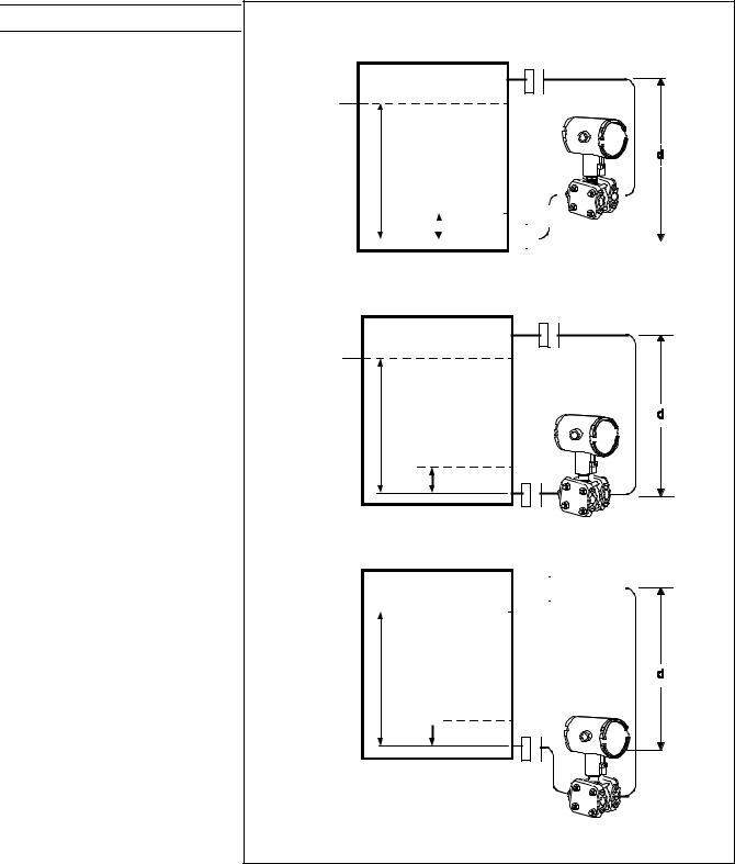
Liquid Level: Closed Tank
Determine the minimum and maximum pressure differentials to be measured (Figure 5).
PMin = (SGp x a) - (SGf x d)
=LRV when HP at bottom of tank
=–URV when LP at bottom of tank
PMax = (SGp x b) - (SGf x d)
=URV when HP at bottom of tank
=–LRV when LP at bottom of tank
Where:
minimum level = 4mA
maximum level = 20 mA
a = distance between bottom tap and minimum level
b = distance between bottom tap and maximum level
d = distance between taps
SGf = Specific Gravity of capillary
fill fluid (See Page 6 for values.)
SGp = Specific Gravity of process fluid
34-ST-03-57
Page 9
Max
LP
Level
Min |
|
|
b |
|
|
|
|
|
|
|
|
|
|||||||||||||||||||||
|
|
|
|
|
|
|
|
|
|
|
|||||||||||||||||||||||
|
|
|
|
|
|
|
|
|
|
|
|
|
|
|
|
|
|
|
|
|
HP |
|
|
|
|
|
|
|
|
|
|||
|
|
|
|
|
|
|
|
|
|
|
|
|
|
|
|
|
|
|
|
|
|
|
|
|
|
|
|
|
|
||||
|
|
|
|
|
|
|
|
|
|
|
|
|
|
|
|
|
|
|
|
|
|
|
|
|
|
|
|
|
|
||||
|
|
|
|
|
|
|
|
|
|
|
|
|
|
|
|
|
|
|
|
|
|
|
|
|
|
|
|
|
|
||||
|
|
|
|
|
|
|
|
|
|
|
|
|
|
|
|
|
|
|
|
|
|
|
|
|
|
|
|
|
|
||||
|
|
|
|
|
|
|
|
|
|
|
|
|
|
|
|
|
|
|
|
|
|
|
|
|
|
|
|
|
|
||||
|
|
|
|
|
|
|
|
|
|
|
|
|
|
|
|
|
|
|
|
|
|
|
|
|
|
|
|
|
|
|
|||
Level |
|
|
|
|
|
|
|
|
|
|
a |
|
|
|
|
|
|
|
|
|
|||||||||||||
|
|
|
|
|
|
|
|
|
|
|
|
|
|
|
|
|
|
|
|
|
|
||||||||||||
|
|
|
|
|
|
|
|
|
|
|
|
|
|
|
|
|
|
|
|
|
|
|
|
|
|
|
|
|
|
|
|
|
|
|
|
|
|
|
|
|
|
|
|
|
|
|
|
|
|
|
|
|
|
|
|
|
|
|
|
|
|
|
|
|
|
|
|
¥ Transmitter above datum
Max |
|
LP |
|
|
|
Level |
|
|
|
b |
|
Min |
|
HP |
|
a |
|
Level |
|
|
|
|
¥ Transmitter at datum
|
|
|
|
|
|
|
|
|
|
|
|
|
|
|
|
|
|
|
|
|
|
|
|
|
|
|
Max |
|
|
|
|||||||||||||||||||||||
LP |
|
|||||||||||||||||||||||||
|
|
|
|
|
|
|
|
|
|
|
|
|
|
|
|
|
|
|
|
|
|
|
|
|
||
Level |
|
|
|
|||||||||||||||||||||||
b
Min
Level

 a HP
a HP
¥ Transmitter below datum
24253
Figure 5—Closed tank liquid level measurement distances
 Loading...