


ST 3000 Smart Transmitter
Release 300 and Smart Field
Communicator Model STS103
User’s Manual
34-ST-25-14 6/08
Honeywell Process Solutions

Copyright, Notices, and Trademarks
© Copyright 2008 by Honeywell Inc.
June 2008
While this information is presented in good faith and believed to be accurate, Honeywell disclaims the implied warranties of merchantability and fitness for a particular purpose and makes no express warranties except as may be stated in its written agreement with and for its customer.
In no event is Honeywell liable to anyone for any indirect, special or consequential damages. The information and specifications in this document are subject to change without notice.
This document was prepared using Information Mapping® methodologies and formatting principles.
TDC 3000, SFC, Smartline and ST 3000 are U.S. registered trademarks of Honeywell Inc.
Information Mapping is a trademark of Information Mapping Inc.
Honeywell Process Solutions
512 Virginia Drive
Fort Washington, PA 19034
ii |
ST 3000 Release 300 and SFC Model STS103 User’s Manual |
6/08 |

About This Publication
This manual is intended as a detailed “how to” reference for installing, piping, wiring, configuring, starting up, operating, maintaining, calibrating, and servicing Honeywell’s family of Release 300 Series 100 and Series 900 ST 3000® Smart Transmitters. It is based on using a model STS103 Smart Field Communicator (SFC®) as the operator interface for the ST 3000 transmitter. Be aware that data in this manual overlaps information in the ST 3000 Smart Transmitter Installation Guide and the Smart Field Communicator Model STS103 Operating Guide to minimize cross reference.
While this manual provides detailed procedures to assist first time users, it also includes keystroke summaries for most procedures as a quick reference for experienced users.
If you will be digitally integrating the ST 3000 transmitter with our TotalPlant® Solution (TPS) system, you will need to supplement this information with data in the PM/APM Smartline® Transmitter Integration Manual which is supplied with the TDC 3000®X bookset. TPS is the evolution of TDC 3000X.
This manual does not apply for non Release 300 Series 100, Series 600, Series 100e and non Release 300 Series 900 transmitter models. If you have a non Release 300 Series 100 or Series 600 ST 3000 Smart Transmitter, refer to the Installation Guide 34-ST-33-28 and User’s Manual 34-ST-25-09 supplied with the transmitter for information. If you have a non Release 300 Series 900 or Series 100e Smart Transmitter, refer to the Installation Guide 34-ST-33-31 and User’s Manual 34-ST-25-11 supplied with the transmitter for information.
Patent Notice
This product is covered by one or more of the following U.S. Patents: 4,520,488; 4,567,466; 4,494,183; 4,502,335; 4,592,002; 4,553,104; 4,541,282; 4,806,905; 4,797,669; 4,735,090; 4,768,382; 4,787,250; 4,888,992; 5,811,690; 5,875,150; 5,765,436; 4,734,873; 6,041,659 and other patents pending.
6/08 |
ST 3000 Release 300 and SFC Model STS103 User’s Manual |
iii |
References
Publication |
Publication |
Binder |
Binder |
Title |
Number |
Title |
Number |
Smart Field Communicator |
34-ST-11-14 |
|
|
Model STS103 |
|
|
|
Operating Guide |
|
|
|
|
|
|
|
ST 3000 Smart Transmitter |
34-ST-33-39 |
|
|
Series 100 and Series 900 |
|
|
|
Release 300 |
|
|
|
Installation Guide |
|
|
|
|
|
|
|
For R400 and later: |
|
|
|
PM/APM Smartline Transmitter |
PM12-410 |
Implementation/ |
TDC 2045 |
Integration Manual |
|
PM/APM Optional Devices |
|
|
|
|
|
Symbol Definitions
This CAUTION symbol on the equipment refers the user to the Product Manual for additional information. This symbol appears next to required information in the manual.
This WARNING symbol on the equipment refers the user to the Product Manual for additional information. This symbol appears next to required information in the manual.
WARNING: risk of electrical shock. This symbol warns the user of a potential shock hazard where HAZARDOUS LIVE voltages greater than 30 Vrms, 42.4 Vpeak, or 60 VDC may be accessible.
ATTENTION, Electrostatic Discharge (ESD) hazards. Observe precautions for handling electrostatic sensitive devices
Protective Earth (PE) terminal. Provided for connection of the protective earth (green or green/yellow) supply system conductor.
Earth Ground. Functional earth connection. NOTE: This connection shall be bonded to Protective earth at the source of supply in accordance with national and local electrical code requirements.
iv |
ST 3000 Release 300 and SFC Model STS103 User’s Manual |
6/08 |

Table of Contents
References.................................................................................................................................................. |
iv |
|
Technical Assistance ................................................................................................................................. |
xiii |
|
SECTION 1 —OVERVIEW - FIRST TIME USERS ONLY................................................. |
1 |
|
1.1 |
Introduction ........................................................................................................................................ |
1 |
1.2 |
ST 3000 Smart Transmitters ............................................................................................................. |
2 |
1.3 |
Smart Field Communicator................................................................................................................ |
8 |
1.4 |
Transmitter/SFC Order .................................................................................................................... |
11 |
1.5 |
Local Smart Meter Options.............................................................................................................. |
13 |
SECTION 2 —QUICK START REFERENCE.................................................................. |
15 |
|
2.1 |
Introduction ...................................................................................................................................... |
15 |
2.2 |
Getting ST 3000 Transmitter On-Line Quickly ................................................................................ |
16 |
SECTION 3 —PREINSTALLATION CONSIDERATIONS .............................................. |
17 |
|
3.1 |
Introduction ...................................................................................................................................... |
17 |
3.2 |
CE Conformity (Europe) Notice....................................................................................................... |
18 |
3.3 |
Considerations for ST 3000 Transmitter ......................................................................................... |
19 |
3.4 |
Considerations for SFC ................................................................................................................... |
22 |
3.5 |
Considerations for Local Smart Meter Option ................................................................................. |
24 |
SECTION 4 —INSTALLATION ....................................................................................... |
25 |
|
4.1 |
Introduction ...................................................................................................................................... |
25 |
4.2 |
Mounting ST 3000 Transmitter........................................................................................................ |
26 |
4.3 |
Piping ST 3000 Transmitter............................................................................................................. |
38 |
4.4 |
Wiring ST 3000 Transmitter............................................................................................................. |
43 |
SECTION 5 —GETTING STARTED ............................................................................... |
49 |
|
5.1 |
Introduction ...................................................................................................................................... |
49 |
5.2 |
Establishing Communications ......................................................................................................... |
50 |
5.3 |
Making Initial Checks....................................................................................................................... |
54 |
5.4 |
Changing Mode of Operation .......................................................................................................... |
57 |
6/08 |
ST 3000 Release 300 and SFC Model STS103 User’s Manual |
v |

Table of Contents
SECTION 6 —CONFIGURATION ................................................................................... |
59 |
|
6.1 |
Introduction ..................................................................................................................................... |
59 |
6.2 |
Overview ......................................................................................................................................... |
60 |
6.3 |
Entering a Tag Number................................................................................................................... |
71 |
6.4 |
Selecting Output Form .................................................................................................................... |
73 |
6.5 |
Adjusting Damping Time................................................................................................................. |
76 |
6.6 |
Selecting Unit of Measurement....................................................................................................... |
78 |
6.7 |
Setting Range Values Using SFC................................................................................................... |
80 |
6.8 |
Setting Range Values Using Local Adjustments ............................................................................ |
84 |
6.9 |
Selecting Output Signal Mode (DE Mode Only) ............................................................................. |
91 |
6.10 |
Selecting Message Format (DE Mode Only) .................................................................................. |
94 |
6.11 |
Configuring Smart Meter Using SFC .............................................................................................. |
96 |
6.12 |
Configuring Smart Meter Using Pushbuttons ............................................................................... |
103 |
6.13 |
Disconnecting SFC ....................................................................................................................... |
122 |
SECTION 7 —STARTUP............................................................................................... |
123 |
|
7.1 |
Introduction ................................................................................................................................... |
123 |
7.2 |
Startup Tasks ................................................................................................................................ |
124 |
7.3 |
Running Analog Output Check ..................................................................................................... |
125 |
7.4 |
Flow Measurement with DP Transmitter....................................................................................... |
128 |
7.5 |
Pressure Measurement with DP Transmitter................................................................................ |
131 |
7.6 |
Liquid Level Measurement - Vented Tank .................................................................................... |
133 |
7.7 |
Liquid Level Measurement - Pressurized Tank ............................................................................ |
136 |
7.8 |
Pressure or Liquid Level Measurement with GP Transmitter ....................................................... |
140 |
7.9 |
Pressure or Liquid Level Measurement with Flush Mount Transmitter ........................................ |
144 |
7.10 |
Pressure Measurement with AP Transmitter ................................................................................ |
145 |
7.11 |
Liquid Level Measurement with DP Transmitter with Remote Seals............................................ |
147 |
SECTION 8 —OPERATION .......................................................................................... |
151 |
|
8.1 |
Introduction ................................................................................................................................... |
151 |
8.2 |
Accessing Operation Data ............................................................................................................ |
152 |
8.3 |
Changing Default Failsafe Direction ............................................................................................. |
155 |
8.4 |
Writing Data in Scratch Pad Area ................................................................................................. |
157 |
8.5 |
Saving and Restoring a Database ................................................................................................ |
159 |
8.6 |
Monitoring Local Smart Meter Display.......................................................................................... |
163 |
SECTION 9 —MAINTENANCE ..................................................................................... |
169 |
|
9.1 |
Introduction ................................................................................................................................... |
169 |
9.2 |
Preventive Maintenance................................................................................................................ |
170 |
9.3 |
Inspecting and Cleaning Barrier Diaphragms ............................................................................... |
171 |
9.4 |
Replacing PWA ............................................................................................................................. |
175 |
9.5 |
Replacing Meter Body................................................................................................................... |
178 |
vi |
ST 3000 Release 300 and SFC Model STS103 User’s Manual |
6/08 |

Table of Contents
SECTION 10 —CALIBRATION..................................................................................... |
183 |
|
10.1 |
Introduction .................................................................................................................................... |
183 |
10.2 |
Overview........................................................................................................................................ |
184 |
10.3 |
Calibrating Analog Output Signal .................................................................................................. |
185 |
10.4 |
Calibrating Range with SFC .......................................................................................................... |
189 |
10.5 |
Resetting Calibration ..................................................................................................................... |
192 |
SECTION 11 —TROUBLESHOOTING......................................................................... |
195 |
|
11.1 |
Introduction .................................................................................................................................... |
195 |
11.2 |
Overview........................................................................................................................................ |
196 |
11.3 |
Clearing the “#” Symbol From SFC Display .................................................................................. |
197 |
11.4 |
Diagnostic Messages .................................................................................................................... |
199 |
11.5 |
Running Status Check................................................................................................................... |
202 |
11.6 |
Interpreting Messages ................................................................................................................... |
203 |
11.7 |
Checking SFC Display and Keyboard ........................................................................................... |
207 |
SECTION 12 —PARTS LIST ........................................................................................ |
209 |
|
12.1 |
Replacement Parts ........................................................................................................................ |
209 |
SECTION 13 —REFERENCE DRAWINGS .................................................................. |
231 |
|
13.1 |
Wiring Diagrams ............................................................................................................................ |
231 |
APPENDIX A – TABLE III OPTIONS IN MODEL NUMBER......................................... |
233 |
|
A.1 |
Table III Options Reference........................................................................................................... |
233 |
APPENDIX B – FREEZE PROTECTION OF TRANSMITTERS ................................... |
237 |
|
B.1 |
Possible Solutions/Methods .......................................................................................................... |
237 |
APPENDIX C – CONFIGURATION RECORD SHEET ................................................. |
251 |
|
APPENDIX D – HAZARDOUS LOCATIONS REFERENCE ......................................... |
253 |
|
D.1 |
North American Classification of Hazardous Locations ................................................................ |
253 |
D.2 |
International Electrotechnical Commission (IEC) Classification of Hazardous Locations ............ |
259 |
D.3 |
Enclosure Ratings ......................................................................................................................... |
263 |
INDEX |
............................................................................................................................ |
266 |
6/08 |
ST 3000 Release 300 and SFC Model STS103 User’s Manual |
vii |

|
Figures |
|
Figure 1 |
Typical ST 3000 Differential Pressure Transmitter................................................................................ |
2 |
Figure 2 |
Functional Block Diagram for Transmitter in Analog Mode of Operation............................................ |
3 |
Figure 3 |
Functional Block Diagram for Transmitter in Digital DE Mode of Operation. ..................................... |
4 |
Figure 4 |
Typical SFC Communication Interface.................................................................................................. |
8 |
Figure 5 |
Typical ST 3000 Transmitter and SFC Order Components. ................................................................ |
11 |
Figure 6 |
ST 3000 with Local Smart Meter Option. ............................................................................................ |
14 |
Figure 7 |
Typical Mounting Area Considerations Prior to Installation ............................................................... |
19 |
Figure 8 |
Typical Bracket Mounted and Flange Mounted Installations............................................................... |
26 |
Figure 9 |
Leveling a Model STA122 or 922 Absolute Pressure Transmitter. ..................................................... |
30 |
Figure 10 |
Typical Flange Mounted Transmitter Installation ................................................................................ |
33 |
Figure 11 |
Typical Flush Mounted Transmitter Installation .................................................................................. |
34 |
Figure 12 |
Typical Pipe and Flange Mounted Installations ................................................................................... |
35 |
Figure 13 |
Typical Remote Diaphragm Seal Transmitter Installation. .................................................................. |
37 |
Figure 14 |
Typical 3-Valve Manifold and Blow-Down Piping Arrangement. ...................................................... |
38 |
Figure 15 |
Typical Piping Arrangement for ½” NPT Process Connection............................................................ |
39 |
Figure 16 |
Operating Range for ST 3000 Transmitters. ........................................................................................ |
43 |
Figure 17 |
ST 3000 Transmitter Terminal Block................................................................................................... |
44 |
Figure 18 |
Ground Connection for Lightning Protection....................................................................................... |
46 |
Figure 19 |
Typical SFC Connections..................................................................................................................... |
50 |
Figure 20 |
Write Protect Jumper Location and Selections..................................................................................... |
55 |
Figure 21 |
Display With All Indicators Lit............................................................................................................ |
56 |
Figure 22 |
Keystroke Summary for Changing Mode of Operation. ...................................................................... |
58 |
Figure 23 |
Summary of Configuration Process...................................................................................................... |
60 |
Figure 24 |
SFC and ST 3000 Transmitter Memories............................................................................................. |
61 |
Figure 25 |
Flowchart — ST 3000 Pressure Transmitter Configuration................................................................. |
66 |
Figure 26 |
Keystroke Summary for Entering Tag Number.................................................................................... |
72 |
Figure 27 |
Keystroke Summary for Selecting Output Conformity. ....................................................................... |
74 |
Figure 28 |
Square Root Dropout Points................................................................................................................. |
75 |
Figure 29 |
Keystroke Summary for Adjusting Damping Time.............................................................................. |
77 |
Figure 30 |
Keystroke Summary for Keying in LRV and URV.............................................................................. |
81 |
Figure 31 |
Keystroke Summary for Setting LRV and URV to Applied Pressures. ............................................... |
83 |
Figure 32 |
Typical Setup for Setting Range Values Using Local Zero and Span Adjustments............................. |
90 |
Figure 33 |
Keystroke Summary for Selecting Mode of Output Signal Indication................................................. |
93 |
Figure 34 |
Keystroke Summary for Selecting Message Format. ........................................................................... |
95 |
Figure 35 |
Keystroke Summary for Configuring Local Smart Meter.................................................................. |
102 |
Figure 36 |
Button Pushing Summary for Selecting Engineering Units. .............................................................. |
120 |
Figure 37 |
Button Pushing Summary for Setting Lower and Upper Display Limits. .......................................... |
121 |
Figure 38 |
Typical SFC and Meter Connections for Constant-Current Source Mode......................................... |
127 |
Figure 39 |
Typical Piping Arrangement for Flow Measurement with DP Type Transmitter .............................. |
128 |
Figure 40 |
Typical Piping Arrangement for Pressure Measurement with DP Type Transmitter......................... |
131 |
Figure 41 |
Typical Piping Arrangement for Liquid Level Measurement with |
|
|
DP Type Transmitter and Vented Tank.............................................................................................. |
133 |
Figure 42 |
Typical Piping Arrangement for Liquid Level Measurement with |
|
|
DP Type Transmitter and Pressurized Tank....................................................................................... |
136 |
Figure 43 |
Typical Piping Arrangement for Pressure Measurement with GP Type Transmitter......................... |
140 |
Figure 44 |
Typical Piping Arrangement for Liquid Level Measurement with GP TypeTransmitter................... |
140 |
Figure 45 |
Typical Arrangement for Pressure Measurement with Flush Mount Transmitter.............................. |
144 |
Figure 46 |
Typical Arrangement for Liquid Level Measurement with Flush Mount Transmitter....................... |
144 |
Figure 47 |
Typical Piping Arrangement for Pressure Measurement with AP Type Transmitter......................... |
145 |
viii |
ST 3000 Release 300 and SFC Model STS103 User’s Manual |
6/08 |

|
Figures |
|
Figure 48 Typical Piping Arrangement for Liquid Level Measurement with |
|
|
|
DP Type Transmitter with Remote Seals ........................................................................................... |
147 |
Figure 49 Location of Failsafe Direction Jumper on PWA. ............................................................................... |
156 |
|
Figure 50 |
Summary of Save and Restore Database Function............................................................................. |
159 |
Figure 51 Display With All Indicators Lit.......................................................................................................... |
163 |
|
Figure 52 |
Typical Calibration Hookup............................................................................................................... |
191 |
Figure 53 |
Major ST 3000 Smart Transmitter Parts Reference. .......................................................................... |
210 |
Figure 54 ST 3000 Transmitter Mounting Bracket Parts Reference. ................................................................. |
211 |
|
Figure 55 |
Series 100/900 Electronics Housing - Electronics/Meter End. .......................................................... |
212 |
Figure 56 |
Series 100/900 Electronics Housing - Terminal Block End............................................................... |
212 |
Figure 57 |
Series 100 and Series 900 DP Meter Body for Models STD924 & STD930 C, D, G, |
|
|
H, K, and L and STD974 ................................................................................................................... |
214 |
Figure 58 |
Series 900 DP Meter Body for Models Models STD924 & STD930 A, B, E, F, and J..................... |
217 |
Figure 59 |
Series 100 GP and AP Meter Bodies and Series 900 AP Meter Body............................................... |
219 |
Figure 60 |
Series 900 Dual-Head GP Meter Bodies............................................................................................ |
221 |
Figure 61 |
Series 100 and Series 900 LGP Meter Body...................................................................................... |
222 |
Figure 62 |
Series 900 Flush Mount Meter Body. ................................................................................................ |
223 |
Figure 63 |
Series 100 and Series 900 Flange Mounted Meter Body. .................................................................. |
224 |
Figure 64 |
High Temperature Meter Body. ......................................................................................................... |
226 |
Figure 65 SFC Smart Field Communicator and Accessories. ............................................................................ |
228 |
|
Figure B-1 |
Piping Installation for Sealing Liquid With Specific Gravity Heavier Than Process Fluid............... |
238 |
Figure B-2 |
Piping Installation for Sealing Liquid with Specific Gravity Lighter Than Process Fluid................. |
239 |
Figure B-3 |
Piping Installation for Gas Flow. ....................................................................................................... |
240 |
Figure B-4 |
Piping Installation for Differential Pressure Transmitter with Metal Diaphragm Seals..................... |
241 |
Figure B-5 |
Piping Installation for Process Pressure Transmitter with Metal Diaphragm Seal............................. |
242 |
Figure B-6 |
Piping Installation for Differential Pressure Transmitter and |
|
|
Impulse Piping with Electric Heating and Control............................................................................. |
243 |
Figure B-7 |
Piping Installation for Process Pressure Transmitter and |
|
|
Impulse Piping with Electric Heating Control. .................................................................................. |
244 |
Figure B-8 |
Piping Installation for Differential Pressure Transmitter and Impulse Piping with Steam Heating... |
247 |
Figure B-9 |
Piping Installation for Process Pressure Transmitter and Impulse Piping with Steam Heating. ........ |
248 |
6/08 |
ST 3000 Release 300 and SFC Model STS103 User’s Manual |
ix |

|
Tables |
|
Table 1 |
ST 3000 Pressure Transmitter Family. ................................................................................................. |
6 |
Table 2 |
SFC Model Differences........................................................................................................................ |
9 |
Table 3 |
Local Smart Meter Available Options................................................................................................ |
13 |
Table 4 |
Start-up Tasks Reference.................................................................................................................... |
16 |
Table 5 |
Operating Temperature Limits (Transmitters with Silicone Fill Fluids) ............................................ |
20 |
Table 6 |
Transmitter Overpressure Ratings...................................................................................................... |
21 |
Table 7 |
Installing and Charging SFC Battery Pack......................................................................................... |
22 |
Table 8 |
Local Smart Meter Specifications. ..................................................................................................... |
24 |
Table 9 |
Mounting ST 3000 Transmitter to a Bracket...................................................................................... |
27 |
Table 10 |
Zero Corrects Procedure for STD110................................................................................................. |
32 |
Table 11 |
Mounting Remote Diaphragm Seal Transmitter................................................................................. |
36 |
Table 12 |
Suggested Transmitter Location for Given Process ........................................................................... |
39 |
Table 13 |
Process Connections........................................................................................................................... |
40 |
Table 14 |
Flange Description ............................................................................................................................. |
41 |
Table 15 |
Installing Flange Adapter ................................................................................................................... |
42 |
Table 16 |
Wiring the Transmitter ....................................................................................................................... |
45 |
Table 17 |
Starting Communications with Transmitter........................................................................................ |
51 |
Table 18 |
Confirming Mode of Operation and Identifying Software Versions.................................................. |
54 |
Table 19 |
Changing Mode of Operation............................................................................................................. |
57 |
Table 20 |
Summary of Pressure Transmitter Configuration Parameters ............................................................ |
63 |
Table 21 |
Entering Tag Number......................................................................................................................... |
71 |
Table 22 |
Selecting Output Conformity ............................................................................................................. |
73 |
Table 23 |
Adjusting Damping Time ................................................................................................................... |
76 |
Table 24 |
Pre-Programmed Engineering Units for Selection ............................................................................. |
78 |
Table 25 |
Keying in LRV and URV................................................................................................................... |
80 |
Table 26 |
Setting LRV and URV to Applied Pressures...................................................................................... |
82 |
Table 27 |
Setting Range Values Using Local Zero and Span Adjustments ....................................................... |
84 |
Table 28 |
Selecting Mode of Output Signal Indication ...................................................................................... |
91 |
Table 29 |
Selecting Message Format.................................................................................................................. |
94 |
Table 30 |
Setting Up Local Smart Meter Configuration Using an SFC ............................................................. |
97 |
Table 31 |
Smart Meter Pushbutton Description ............................................................................................... |
103 |
Table 32 |
Smart Meter Engineering Units Code .............................................................................................. |
105 |
Table 33 |
Selecting Engineering Units ............................................................................................................. |
106 |
Table 34 |
Smart Meter Restrictions for Setting Display Values....................................................................... |
109 |
Table 35 |
Setting Lower Display Values for Smart Meter Display.................................................................. |
110 |
Table 36 |
Setting Upper Display Value for Smart Meter Display.................................................................... |
114 |
Table 37 |
Startup Procedure Reference ............................................................................................................ |
124 |
Table 38 |
Using Transmitter in Constant-Current Source Mode...................................................................... |
125 |
Table 39 |
Starting Up DP Transmitter for Flow Measurement With SFC ....................................................... |
128 |
Table 40 |
Starting Up DP Transmitter for Pressure Measurement With SFC.................................................. |
131 |
Table 41 |
Starting Up DP Transmitter for Liquid Level Measurement in Vented Tank .................................. |
134 |
Table 42 |
Starting Up DP Transmitter for Liquid Level Measurement in Pressurized Tank ........................... |
137 |
Table 43 |
Starting Up GP Transmitter for Pressure or Liquid Level Measurement With SFC........................ |
141 |
Table 44 |
Starting Up AP Transmitter for Pressure Measurement With SFC.................................................. |
145 |
Table 45 |
Starting Up DP Transmitter with Remote Seals for Liquid Level Measurement with SFC............. |
148 |
Table 46 |
Summary of Keystrokes for Operation Data Access........................................................................ |
152 |
Table 47 |
Cutting Failsafe Direction Jumper.................................................................................................... |
156 |
Table 48 |
Writing Data in Scratch Pad Area .................................................................................................... |
157 |
Table 49 |
Saving and Restoring a Database ..................................................................................................... |
160 |
x |
ST 3000 Release 300 and SFC Model STS103 User’s Manual |
6/08 |
|
Tables |
|
Table 50 |
Description of Display Indicators Shown in Figure 51.................................................................... |
163 |
Table 51 |
Summary of Typical Local Smart Meter Indications. ...................................................................... |
165 |
Table 52 |
Possible Smart Meter Error Codes. .................................................................................................. |
166 |
Table 53 |
Inspecting and Cleaning Barrier Diaphragms .................................................................................. |
171 |
Table 54 |
Process Head Bolt Torque Ratings................................................................................................... |
174 |
Table 55 |
Replacing PWA................................................................................................................................ |
175 |
Table 56 |
Replacing Meter Body Only............................................................................................................. |
178 |
Table 57 |
Calibrating Output Signal for Transmitter in Analog Mode ............................................................ |
185 |
Table 58 |
Calibrating Measurement Range With SFC ..................................................................................... |
189 |
Table 59 |
Resetting Calibration Data With SFC .............................................................................................. |
193 |
Table 60 |
Clearing the # Symbol from the SFC Display.................................................................................. |
197 |
Table 61 |
Summary of Diagnostic Messages for Non-Critical Failures........................................................... |
199 |
Table 62 |
Summary of Diagnostic Messages for Critical Failures................................................................... |
200 |
Table 63 |
Summary of Diagnostic Messages for Communication Errors ........................................................ |
200 |
Table 64 |
Summary of Diagnostic Messages for Invalid Key Entry Errors..................................................... |
201 |
Table 65 |
Summary of Interrupt Messages For SFC Display........................................................................... |
201 |
Table 66 |
Running a Status Check With SFC .................................................................................................. |
202 |
Table 67 |
Diagnostic Message Interpretation Table......................................................................................... |
203 |
Table 68 |
Running SFC Display and Keyboard Test ....................................................................................... |
207 |
Table 69 |
Major ST 3000 Smart Transmitter Parts Reference. ........................................................................ |
211 |
Table 70 |
Parts Identification for Callouts in Figures 55 and 56...................................................................... |
213 |
Table 71 |
Parts Identification for Callouts in Figure 57................................................................................... |
215 |
Table 72 |
Parts Identification for Callouts in Figure 58................................................................................... |
218 |
Table 73 |
Parts Identification for Callouts in Figure 59................................................................................... |
219 |
Table 74 |
Replacement GP and AP Process Head Part Numbers for Narrow Profile Meter Body.................. |
220 |
Table 75 |
Parts Identification for Callouts in Figure 60................................................................................... |
221 |
Table 76 |
Parts Identification for Callouts in Figure 61................................................................................... |
222 |
Table 77 |
Parts Identification for Callouts in Figure 62................................................................................... |
223 |
Table 78 |
Parts Identification for Callouts in Figure 63................................................................................... |
225 |
Table 79 |
Parts Identification for Callouts in Figure 64................................................................................... |
226 |
Table 80 |
Parts Identification for Callouts in Figure 65................................................................................... |
229 |
Table 81 |
Summary of Recommended Spare Parts .......................................................................................... |
230 |
Table B-1 |
Temperature Range of Freeze Protection Systems........................................................................... |
246 |
Table B-2 Steam Pressure Versus Steam Temperature Values ......................................................................... |
250 |
|
Table D-1 |
Factory Mutual (FM) Entity Parameters .......................................................................................... |
257 |
Table D-2 |
CSA Entity Parameters..................................................................................................................... |
258 |
Table D-3 |
CENELEC / LCIE Certification....................................................................................................... |
261 |
Table D-4 |
Standards Australia (LOSC) Certification........................................................................................ |
262 |
Table D-5 Zone 2 (Europe) Declaration of Conformity.................................................................................... |
262 |
|
Table D-6 |
NEMA Enclosure Type Numbers and Comparable IEC Enclosure Classification .......................... |
264 |
6/08 |
ST 3000 Release 300 and SFC Model STS103 User’s Manual |
xi |

|
Acronyms |
|
|
AP.......................................................................................................................... |
Absolute Pressure |
APM ....................................................................................................... |
Advanced Process Manager |
AWG .............................................................................................................. |
American Wire Gauge |
DE .................................................................................... |
Digital Enhanced Communications Mode |
DP...................................................................................................................... |
Differential Pressure |
EMI....................................................................................................... |
Electromagnetic Interference |
GP.............................................................................................................................. |
Gauge Pressure |
HP................................................................................................................................. |
High Pressure |
HP............................................................................................. |
High Pressure Side (DP Transmitter) |
inH2O ........................................................................................................................ |
Inches of Water |
LGP ............................................................................................................... |
In-Line Gauge Pressure |
LP .................................................................................................................................. |
Low Pressure |
LP ............................................................................................. |
Low Pressure Side (DP Transmitter) |
LRV.................................................................................................................... |
Lower Range Value |
mA................................................................................................................................. |
Milliamperes |
mmHg............................................................................................................ |
Millimeters of Mercury |
NPT .................................................................................................................. |
National Pipe Thread |
PCB .................................................................................................................. |
Printed Circuit Board |
PM ............................................................................................................................. |
Process Manger |
PROM......................................................................................... |
Programmable Read Only Memory |
PSI ................................................................................................................ |
Pounds per Square Inch |
PSIA .............................................................................................. |
Pounds per Square Inch Absolute |
RFI....................................................................................................... |
Radio Frequency Interference |
SFC.......................................................................................................... |
Smart Field Communicator |
TPS..................................................................................................................... |
TotalPlant Solution |
URL..................................................................................................................... |
Upper Range Limit |
URV .................................................................................................................... |
Upper Range Value |
Vdc ..................................................................................................................... |
Volts Direct Current |
XMTR .............................................................................................................................. |
Transmitter |
xii |
ST 3000 Release 300 and SFC Model STS103 User’s Manual |
6/08 |

Technical Assistance
If you encounter a problem with your ST 3000 Smart Transmitter, check to see how your transmitter is currently configured to verify that all selections are consistent with your application.
If the problem persists, you can reach Honeywell’s Solution Support Center for technical support by telephone during normal business hours. An engineer will discuss your problem with you. Please have your complete model number, serial number, and software revision number on hand for reference. You can find the model and serial numbers on the transmitter nameplates. You can also view the software version number using the SFC or SCT 3000 software application.
By Telephone |
Honeywell Solution Support Center Phone: |
|
|
1-800-423-9883 |
(U.S. only) |
|
Outside the U.S. call: 1-602-313-6510 |
|
Additional Help |
You may also seek additional help by contacting the Honeywell |
|
|
distributor who supplied your ST 3000 transmitter. |
|
By E-mail |
You can also e-mail your technical questions or comments about this |
|
|
product to: |
|
|
Honeywell Solution Support Center e-mail: ace@honeywell.com |
|
Problem Resolution |
If it is determined that a hardware problem exists, a replacement |
|
|
transmitter or part will be shipped with instructions for returning the |
|
|
defective unit. Please do not return your transmitter without |
|
|
authorization from Honeywell’s Solution Support Center or until the |
|
|
replacement has been received. |
|
6/08 |
ST 3000 Release 300 and SFC Model STS103 User’s Manual |
xiii |

Section 1 —Overview - First Time Users Only
1.1Introduction
Section contents
About this section
ATTENTION
This section includes these topics:
Section |
Topic |
See Page |
|
1.1 |
Introduction |
.................................................................................... |
1 |
1.2 |
ST 3000 Transmitters..................................................................... |
2 |
|
1.3 |
Smart Field .............................................................Communicator |
8 |
|
1.4 |
Transmitter/SFC .................................................................Order |
11 |
|
1.5 |
Local Smart ...........................................................Meter Options |
13 |
|
This section is intended for users who have never worked with our
ST 3000 Smart Transmitter and its companion operator interface device the hand-held Smart Field Communicator (SFC®) before. It provides some general information to acquaint you with the ST 3000 transmitter and the SFC.
Honeywell also offers the SCT 3000 Smartline Configuration Toolkit that runs on a variety of Personal Computer (PC) platforms using MSDOS 5.0 or higher and Windows 3.1 or higher. It is a bundled Microsoft Windows software and PC-interface hardware solution that allows quick, error-free configuration of Honeywell Smartline field instruments. Some SCT 3000 features include:
•Preconfigured templates that simplify configuration and allow rapid development of configuration databases.
•Context-sensitive help and an on-line user manual.
•Extensive menus and prompts that minimize the need for prior training or experience.
•The ability to load previously configured databases at time of installation.
•Automatic verification of device identification and database configuration menus and prompts for bench set up and calibration.
•The ability to save unlimited transmitter databases on the PC.
SCT 3000 Release 3.12.2 or greater is compatible with our latest Series 100 and 900, Release 300, ST 3000 transmitters. Please contact your Honeywell representative for more information.
6/08 |
ST 3000 Release 300 and SFC Model STS103 User’s Manual |
1 |
1.2ST 3000 Smart Transmitters
About the transmitter The ST 3000 Smart Transmitter comes in a variety of models for measurement applications involving one of these basic types of pressure:
•Differential Pressure
•Gauge Pressure
•Absolute Pressure
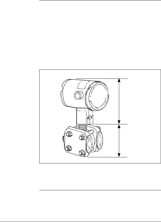
The transmitter measures the process pressure and transmits an output signal proportional to the measured variable over a 4 to 20 milliampere, two-wire loop. Its major components are an electronics housing and a meter body as shown in Figure 1 for a typical differential pressure model transmitter.
Figure 1 Typical ST 3000 Differential Pressure Transmitter.
Electronics
Housing
Meter Body
The ST 3000 can transmit its output in either an analog 4 to 20 milliampere format or a digital DE protocol format for direct digital communications with our TPS system, Allen-Bradley PLCs and other control systems.
Continued on next page
2 |
ST 3000 Release 300 and SFC Model STS103 User’s Manual |
6/08 |
1.2 ST 3000 Smart Transmitters, Continued
About the transmitter, continued
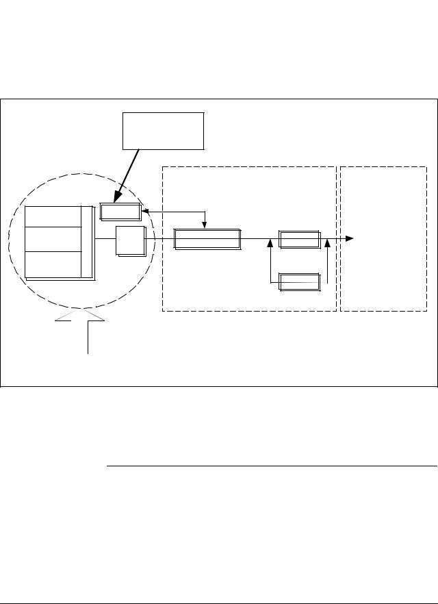
Besides the process variable (PV) output, the transmitter also provides its meter body temperature as a secondary variable which is only available as a read-only parameter through the SFC when the transmitter is in its analog mode. See Figure 2.
Figure 2 Functional Block Diagram for Transmitter in Analog Mode of Operation.
|
|
Factory |
|
|
|
|
|
Characterization |
|
|
|
|
|
Data |
|
|
|
Meter Body |
|
|
Electronics Housing |
||
|
|
|
|
||
DP or PP |
|
PROM |
|
|
|
|
|
|
|
|
|
Sensor |
Multiplexer |
|
|
|
|
Temperature |
A/D |
Microprocessor |
D/A |
Proportional 4 to |
|
Sensor |
|
|
|
20 mA PV output. |
|
Static Pressure |
|
|
|
(Digital signal |
|
Sensor |
|
|
|
|
imposed during |
|
|
|
|
Digital I/O |
SFC |
|
|
|
|
communications) |
|
|
|
|
Modular Electronics |
Terminal Block |
|
Pressure |
|
|
|
|
|
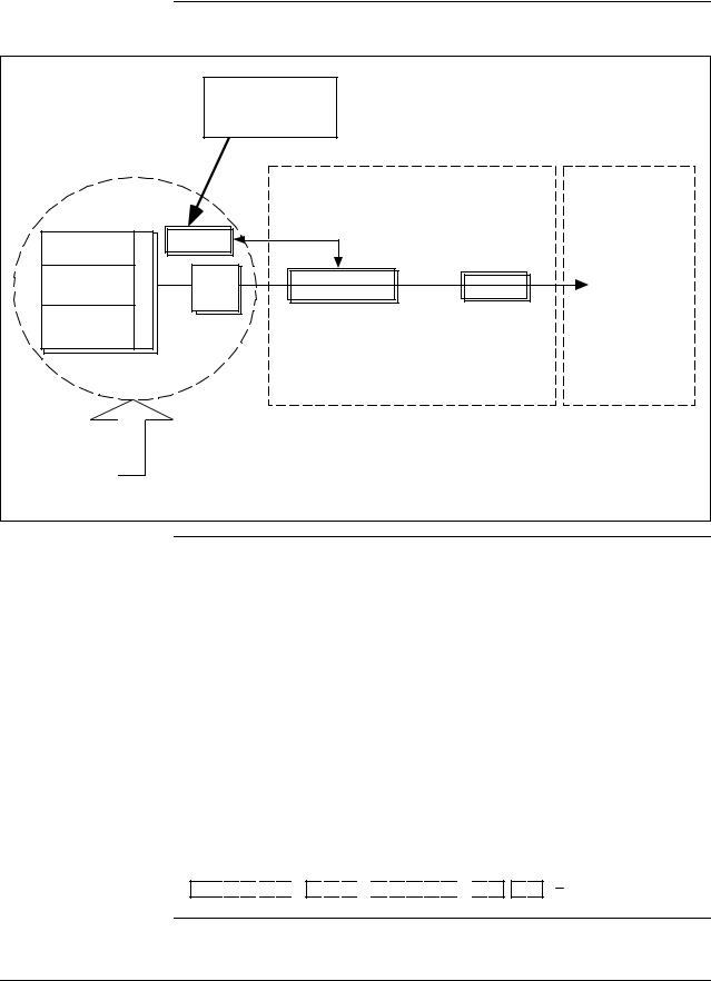
When the transmitter is in its DE mode, the process variable is available for monitoring and control purposes; and the meter body temperature is also available as a secondary variable for monitoring purposes only.
See Figure 3.
Continued on next page
6/08 |
ST 3000 Release 300 and SFC Model STS103 User’s Manual |
3 |
1.2ST 3000 Smart Transmitters, Continued
Figure 3 Functional Block Diagram for Transmitter in Digital DE Mode of Operation.
|
|
Factory |
|
|
|
|
|
Characterization |
|
|
|
|
|
Data |
|
|
|
Meter Body |
|
|
Electronics Housing |
||
|
|
|
|
||
DP or PP |
|
PROM |
|
|
|
|
|
|
|
|
|
Sensor |
Multiplexer |
|
|
|
|
Temperature |
A/D |
Microprocessor |
Digital I/O |
Digital signal |
|
Sensor |
|
|
|
broadcasts PV |
|
|
|
|
|
||
Static Pressure |
|
|
|
in floating point |
|
Sensor |
|
|
|
|
format over |
|
|
|
|
|
20 mA loop. |
|
|
|
Modular Electronics |
Terminal Block |
|
Pressure |
|
|
|
|
|
Series and model number data
Honeywell’s line of ST 3000 Smart Transmitters includes these two series designations:
•Series 100
•Series 900
Each series includes several models to meet various process pressure measurement and interface requirements. Each transmitter comes with a nameplate located on the top of the electronics housing that lists its given “model number”. The model number format consists of a Key Number with several Table selections as shown below.
|
ype |
sic |
T |
|
|
Ba |
|
Key Number
S 
 T
T 
 D
D 
 1
1 
 2
2 
 0
0 

|
|
|
|
|
|
ly |
|
|
|
|
|
|
b |
|
|
|
|
|
|
|
m |
|
|
|
y |
|
|
se |
|
|
|
|
d |
|
|
As |
|
|
s |
r |
Bo |
|
e |
|
|
|
|
|
|
|
|
n |
|||
|
|
|
ng |
|
|
t |
|
ete |
|
la |
|
|
io |
|
|
|
|
|
p |
|
|||
M |
|
F |
|
|
|
O |
|
Table I |
Table II |
|
|
Table III |
|
||
E 
 1
1 
 H
H

 0
0 
 0
0 
 0
0 
 0
0 
 0
0 

 S
S 
 B , 1
B , 1 
 C
C
|
ion |
|
at |
c |
|
Identifi |
|
|
y |
r |
|
to |
|
ac |
|
F |
|
Table IV
X X X X
Continued on next page
4 |
ST 3000 Release 300 and SFC Model STS103 User’s Manual |
6/08 |

1.2 ST 3000 Smart Transmitters, Continued
Series and model number data, continued
ATTENTION
Transmitter adjustments
You can quickly identify what series and basic type of transmitter you have from the third and fourth digits in the key number. The letter in the third digit represents one of these basic transmitter types:
A = Absolute Pressure D = Differential Pressure F = Flange Mounted
G = Gauge Pressure
R = Remote Seals
The number in the fourth digit matches the first digit in the transmitter Series. Thus, a “1” means the transmitter is a Series 100 and a “9” is a Series 900.
For a complete breakdown of the Table selections in your model number, please refer to the appropriate Specification and Model Selection Guide that is provided as a separate document. However, a description of the available Table III options is given in Appendix A of this manual for handy reference.
Previous models of the ST 3000 transmitter with designations of Series 100, Series 100e, Series 600, and Series 900 have been supplied at various times since the ST 3000 was introduced in 1983. While all these transmitters are functionally alike, there are differences in housing and electronics design. This manual only applies for Release 300, Series 100 transmitters with software version 3.0 or greater and Release 300, Series 900 transmitters with software version b.0 or greater. See the procedure on page 50 to use the SFC to check your transmitter’s software version.
Release 300 transmitters can be identified by the “R300” designation on the nameplate.
Except for optional zero and span adjustments, the ST 3000 has no physical adjustments. You need an SFC to make any adjustments in an ST 3000 transmitter. Alternately, certain adjustments can be made through the Universal Station if the transmitter is digitally integrated with a Honeywell TPS system; or through a PC running Honeywell SCT 3000 software.
ST 3000 Transmitters Table 1 illustrates the present ST 3000 pressure transmitter family. presently available
Continued on next page
6/08 |
ST 3000 Release 300 and SFC Model STS103 User’s Manual |
5 |

1.2ST 3000 Smart Transmitters, Continued
Table 1 ST 3000 Pressure Transmitter Family.
Transmitter Type |
Series 100 Model |
Series 900 Model |
Differential |
STD1xx |
STD9xx |
Pressure |
|
|
Differential Pressure |
STF1xx |
STF9xx |
with Flange on One |
|
|
Side |
|
|
Dual-Head Gauge |
Not Available |
STG9xx |
Pressure |
|
|
In-Line Gauge and |
STG1xL |
STG9xL |
Absolute Pressure |
STA1xL |
STA9xL |
|
Gauge and Absolute |
STG1xx |
STG9xx |
Pressure |
STA1xx |
STA9xx |
|
Continued on next page
6 |
ST 3000 Release 300 and SFC Model STS103 User’s Manual |
6/08 |
1.2ST 3000 Smart Transmitters, Continued
Table 1 ST 3000 Pressure Transmitter Family, continued.
Transmitter Type |
|
Series 100 Model |
|
Series 900 Model |
||||
|
|
|
|
|
|
|
|
|
|
|
|
|
|
|
|
|
|
|
|
|
|
|
|
|
|
|
Flange-Mount |
STF1xx |
STF9xx |
Liquid Level |
|
|
Differential Pressure |
STR1xx |
STR9xx |
|
with Remote |
|||
|
|
||
Diaphragm Seals |
|
|
Flush Mount |
Not Available |
STG93P |
|
|
High Temperature |
STG14T |
Not Available |
|
||
|
STF14T |
|
|
|
|
|
|
|
|
|
|
|
|
|
|
|
|
|
|
|
|
|
|
|
|
|
|
|
|
|
|
|
|
|
|
|
|
|
|
|
|
|
|
|
|
|
|
|
|
|
|
|
|
|
|
|
|
|
|
|
|
|
|
|
|
|
|
|
|
|
|
|
|
|
|
|
|
|
|
|
|
|
|
|
|
|
|
|
|
|
|
|
|
|
|
|
|
|
|
|
|
|
|
|
|
|
|
|
|
|
|
|
|
|
|
|
|
|
|
|
|
|
|
|
|
|
|
|
|
|
|
|
|
|
|
|
|
|
|
|
|
|
|
|
|
|
|
|
|
|
|
|
|
|
|
|
|
|
|
|
|
|
|
|
|
|
|
|
|
|
|
|
|
|
|
|
|
|
|
|
|
|
|
|
|
|
|
|
|
|
|
|
|
|
|
|
|
|
|
|
|
|
|
|
|
|
|
|
|
|
|
|
|
|
|
|
|
|
|
|
|
|
|
|
|
|
|
|
|
|
|
|
|
|
|
|
|
|
|
|
|
|
|
|
|
|
|
|
|
|
|
|
|
|
|
|
|
|
|
|
|
|
|
|
|
|
|
|
|
|
|
|
|
|
|
|
|
|
|
|
|
|
|
|
|
|
|
|
|
|
|
|
|
|
|
|
|
|
|
|
|
6/08 |
ST 3000 Release 300 and SFC Model STS103 User’s Manual |
7 |
||||||||||||||||||||
1.3Smart Field Communicator
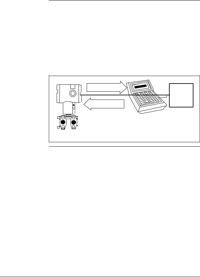
About SFC communications
The portable, battery-powered SFC serves as the common communication interface device for Honeywell’s family of Smartline Transmitters. It communicates with a transmitter through serial digital signals over the 4 to 20 milliampere line used to power the transmitter. A request/response format is the basis for the communication operation. The transmitter’s microprocessor receives a communication signal from the SFC, identifies the request, and sends a response message.
Figure 4 shows a simplified view of the communication interface provided by an SFC.
Figure 4 Typical SFC Communication Interface.
Response |
Power |
|
|
||
4 to 20 mA line |
Supply and |
|
Receiver |
||
Request |
||
|
SFC
|
|
|
|
|
|
STR3001 |
|
ST 3000 |
|||||
|
|
|||||
Purpose of SFC |
The SFC allows you to adjust transmitter values, or diagnose potential |
|
|
problems from a remote location such as the control room. You can use |
|
|
the SFC to: |
|
|
• Configure: |
Define and enter the transmitter’s operating parameters |
including
–range values,
–output conformity,
–damping time,
–tag number (ID), and more
• |
Monitor: |
Read the input pressure to the transmitter in |
|
|
engineering units and the transmitter’s output in |
• |
|
percent. |
Display: |
Retrieve and display data from the transmitter or SFC |
|
• |
Change Mode |
memory. |
|
||
|
of Operation: |
Tell transmitter to operate in either its analog (4-20 |
|
|
mA) mode or its digital enhanced (DE) mode. |
|
|
|
|
|
Continued on next page |
8 |
ST 3000 Release 300 and SFC Model STS103 User’s Manual |
6/08 |

1.3 Smart Field Communicator, Continued
Purpose of SFC, continued
SFC model differences
• Check Current |
|
Output: |
Use the transmitter to supply the output current |
desired |
for verifying analog loop operation, troubleshooting, |
or calibrating other components in the analog loop.
• Troubleshoot: Check status of transmitter operation and display diagnostic messages to identify transmitter, communication, or operator error problems.
As Honeywell’s family of Smartline Transmitters has evolved, the SFC has been changed to meet new model and functionality requirements. Besides different software versions, some major differences exist between these four SFC model designations.
•STS100
•STS101
•STS102
•STS103
Table 2 summarizes the differences between the four SFC models for reference.
Table 2 |
SFC Model Differences |
|
|
|
|
|
|
|
If SFC |
Then it is compatible |
And additional functions |
|
model is. . . |
with. . . |
include . . . |
|
|
|
|
|
STS100 |
Analog only ST 3000 smart |
Not applicable |
|
|
pressure transmitters |
|
|
|
|
|
|
STS101 |
Analog only ST 3000 smart |
Corrects Reset, Failsafe Direction |
|
|
pressure transmitters, if |
and Sensor Temperature |
|
|
SFC software version is less |
indication. |
|
|
than 5.0. |
|
|
|
Analog and Digital (DE) |
Changing the mode from analog |
|
|
mode ST 3000 pressure |
to digital or digital to analog, |
|
|
transmitters and STT 3000 |
configuration parameters for STT |
|
|
temperature transmitters, if |
3000 and scratch pad |
|
|
SFC software version is 5.0 |
configuration area for ST 3000. |
|
|
or greater. |
|
|
|
|
|
|
|
|
Continued on next page |
6/08 |
ST 3000 Release 300 and SFC Model STS103 User’s Manual |
9 |

1.3 Smart Field Communicator, Continued
SFC model differences, continued
ATTENTION
|
Table 2 |
SFC Model Differences, continued |
|
|
If SFC |
Then it is compatible |
And additional functions |
|
model is. . . |
with. . . |
include . . . |
|
|
|
|
|
STS102 |
Analog and Digital (DE) |
Changing the mode from analog |
|
|
mode ST 3000 pressure |
to digital or digital to analog. |
|
|
transmitters, STT 3000 |
Configuration parameters for |
|
|
temperature transmitters, |
Magnew 3000 as well as scratch |
|
|
and MagneW 3000 |
pad configuration area. |
|
|
electromagnetic flowmeters. |
|
|
|
|
|
|
STS103 |
Same as STS102 plus new |
Two-line, 16-character per line |
|
|
multivariable transmitters - |
display. Made “SAVE” and |
|
|
SCM 3000 Smart Coriolis |
“RESTORE” functions part of |
|
|
Flowmeter and SGC 3000 |
configuration menu instead of |
|
|
Smart Gas Chromatograph. |
dedicated keys. Configuration |
|
|
|
parameters for SCM 3000 and |
|
|
|
SGC 3000. |
|
|
SMV 3000 Smart |
Configuration parameters for |
|
|
Multivariable Transmitters, if |
SMV 3000 |
|
|
SFC software version is 4.2 |
|
|
|
or greater. |
|
|
|
SMV 3000 with superheated |
SMV 3000 configuration |
|
|
steam algorithm and |
parameters for superheated steam |
|
|
thermocouple input, if SFC |
algorithm and thermocouple |
|
|
software version is 4.4 or |
inputs. |
|
|
greater. |
|
|
|
Release 300 Series 100 and |
Local Smart Meter configuration |
|
|
900 ST 3000 pressure |
parameters. |
|
|
transmitters, if SFC software |
|
|
|
version is 5.0 or greater. |
|
|
|
|
|
|
|
|
|
The keystroke actions and prompt displays referenced in this manual are for the SFC model STS103. While the SFC model STS103 does have a two-line instead of a one-line display, many of the basic keystrokes and configuration parameter prompts for ST 3000 pressure transmitters are identical to those in the model STS102.
If you will be using a model STS102 SFC, you must refer to the SFC Smart Field Communicator Operating Guide 34-ST-11-10 for keystroke details. But, be aware that transmitter functions will be limited to only those that are supported by the Model STS102 SFC.
10 |
ST 3000 Release 300 and SFC Model STS103 User’s Manual |
6/08 |
1.4Transmitter/SFC Order
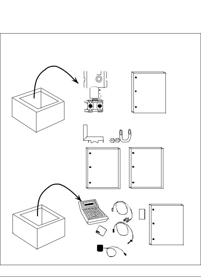
Order components |
Figure 5 shows the components that would be shipped and received for |
|
a typical ST 3000 transmitter and SFC order. |
Figure 5 Typical ST 3000 Transmitter and SFC Order Components.
Ordered
Series 100 ST 3000 Differential pressure transmitter with optional mounting bracket
Smart Field Communicator with optional battery charger
Shipped |
Received |
|
ST 3000 |
ST 3000
Installation
Guide
Mounting Bracket (Optional)
|
|
|
|
|
|
|
|
|
|
|
|
|
|
|
|
|
|
|
|
|
|
|
|
|
|
|
|
|
|
|
|
|
|
|
|
|
|
|
|
|
|
|
|
|
|
|
|
|
|
|
|
|
|
|
|
|
|
|
|
|
Quick |
|
ST 3000 |
|
|
|
|
Shipped |
|||
User'sManual |
|
|
|
|
Reference |
separately, |
||
|
|
|
|
|
|
|
Guide |
if ordered |
|
|
|
|
|
|
|
|
|
|
|
|
|
|
|
|
|
|
|
|
|
|
|
|
|
|
|
|
SFC |
|
SFC |
|
|
Operating |
|
|
|
Guide |
|
|
|
Card |
|
|
Battery |
Leads |
|
|
Pack |
|
|
|
|
Battery |
|
|
|
Charger |
|
|
|
(optional) |
|
|
|
|
Continued on next page |
6/08 |
ST 3000 Release 300 and SFC Model STS103 User’s Manual |
11 |
|

1.4Transmitter/SFC Order, Continued
About documentation Various documents are available for reference describing how to install, configure and operate the ST 3000 transmitter:
•ST 3000 Smart Transmitter Installation Guide Using SFC Model STS103 34-ST-33-39: One copy is shipped with every transmitter. This document provides information for checking, installing, and wiring the ST 3000 transmitter for operation.
•ST 3000 Smart Transmitter and SFC Smart Field Communicator Model STS 103 User’s Manual 34-ST-25-14: One or more copies are sent to the address designated on the order when specified. This document provides detailed information for installing, wiring, configuring, starting up, operating, maintaining, and servicing the ST 3000 transmitter. This is the main reference manual for the ST 3000 transmitter and it overlaps some data in the previously listed Installation Guide 34-ST-33-39 and in the following Operating Guide 34-ST-11-14 to minimize cross reference.
•ST 3000 Smart Transmitter Quick Reference Guide 34-ST-09-06: Shipped with User’s Manual. This document provides abbreviated versions of procedures for installing, wiring, configuring, calibrating and troubleshooting the ST 3000 transmitter for quick reference.
•Smart Field Communicator Model STS103 Pocket Card 34-ST-11-15: One card is shipped with every SFC. This card provides quick reference of keystroke actions for selected transmitter interface tasks.
•Smart Field Communicator Model STS103 Operating Guide 34-ST- 11-14: One copy is shipped with every SFC. This document provides detailed SFC information and keystroke actions for interfacing with these Honeywell Smartline Transmitters.
–ST 3000 Smart Pressure Transmitter (Non Release 300 models)
–STT 3000 Smart Temperature Transmitter
–MagneW 3000 Smart Electromagnetic Flowmeter
–SMV 3000 Smart Multivariable Transmitter
•Smartline Configuration Toolkit SCT 3000 Installation and Start-up Guide 34-ST-10-08: One copy is shipped when the SCT 3000 software application is ordered.
12 |
ST 3000 Release 300 and SFC Model STS103 User’s Manual |
6/08 |
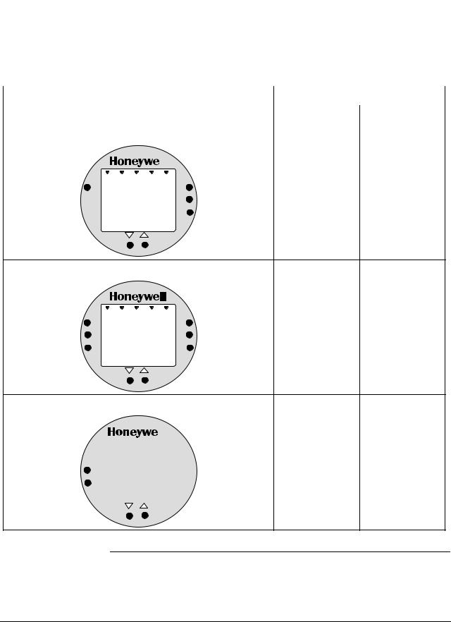
1.5Local Smart Meter Options
Option availability |
Depending upon your transmitter model, it can be equipped with one of |
||||||
|
|
|
the available Local Smart Meter and/or Zero and Span Adjust options as |
||||
|
|
|
shown in Table 3. |
|
|
||
Table 3 |
Local Smart Meter Available Options |
|
|
||||
|
|
|
|
|
|||
|
|
Option Description |
Available with Transmitter Series |
||||
|
|
|
|
|
|
|
|
|
|
|
|
|
|
100 |
900 |
|
|
|
|
|
|
|
|
|
Local Smart Meter only |
|
|
|
|
|
|
|
|
VAR |
|
|
UPPER |
|
|
|
|
|
|
|
|
||
|
|
|
|
|
|
||
|
|
SEL. |
|
|
VALUE |
Yes |
Yes |
|
|
0 |
% |
100 |
|||
|
|
|
|
|
UNITS |
|
|
|
|
|
|
|
SET |
|
|
|
|
|
|
|
LOWER |
|
|
|
|
|
|
|
VALUE |
|
|
Local Smart Meter with Zero and Span Adjustments |
|
|||
VAR |
|
|
UPPER |
|
SEL. |
|
|
VALUE |
Yes |
0 |
% |
100 |
Yes * |
|
SPAN |
|
|
UNITS |
|
|
|
|
SET |
|
ZERO |
|
|
LOWER |
|
|
|
|
VALUE |
|
Local Zero and Span Adjustments only
|
Yes * |
Yes |
|
SPAN
ZERO
* Except draft range, model STD110
Continued on next page
6/08 |
ST 3000 Release 300 and SFC Model STS103 User’s Manual |
13 |
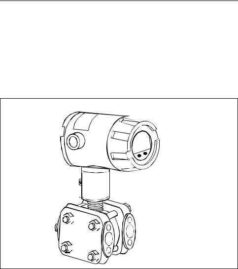
1.5Local Smart Meter Options, Continued
About the options |
Each Local Smart Meter and/or Zero and Span Adjust option comes as a |
|
separate assembly mounted on the transmitter’s Printed Wiring |
|
Assembly (PWA) mounting bracket. The meter option assembly |
|
includes a cable and plug assembly for mating with a connector on the |
|
transmitter’s PWA. A meter end-cap which includes a window is |
|
supplied on the electronics side of the transmitter’s housing so you can |
|
view the meter display with the end cap installed. See Figure 6. |
Figure 6 ST 3000 with Local Smart Meter Option.
Electronics
Housing
 Local Smart
Meter Option
|
|
|
|
|
|
|
|
|
|
|
|
|
|
|
|
|
|
|
|
|
|
|
|
|
|
|
|
|
|
|
|
|
|
|
|
|
|
|
|
|
|
|
|
|
|
|
|
|
|
|
|
|
|
|
|
|
|
|
|
|
|
|
|
|
|
|
|
|
|
|
|
|
|
|
|
|
|
|
|
|
|
|
|
|
|
|
|
|
|
|
|
|
|
|
|
|
|
|
|
|
|
|
|
|
|
|
|
|
|
|
|
|
|
|
|
|
|
|
|
|
|
|
|
|
|
|
|
|
|
|
|
|
|
|
|
|
|
|
|
|
|
|
|
|
|
|
|
|
|
|
|
|
|
|
|
|
|
|
|
|
|
|
|
|
|
|
|
|
|
|
|
|
|
|
|
|
|
|
|
|
|
|
|
|
|
|
|
|
|
|
|
|
|
|
|
|
|
|
|
|
|
|
|
|
|
|
|
|
|
|
|
|
|
|
|
|
|
|
|
|
|
|
|
|
|
|
|
|
|
|
|
|
|
|
|
|
|
|
|
|
|
|
|
|
|
|
|
|
|
|
|
|
|
|
|
|
|
|
|
|
|
|
|
|
|
|
|
|
|
|
|
|
|
|
|
|
|
|
|
|
|
|
|
|
|
|
|
|
|
|
|
|
|
|
|
|
|
|
|
|
|
|
|
|
|
|
|
|
|
|
|
|
|
|
|
|
|
|
|
|
|
|
|
|
|
|
|
|
|
|
|
|
|
|
|
|
|
|
|
|
|
|
|
|
|
|
|
|
|
|
|
|
|
|
|
|
|
|
|
|
|
|
|
|
|
|
|
|
|
|
|
|
|
|
|
|
|
|
|
|
|
|
|
|
|
|
|
|
|
|
|
|
|
|
|
|
|
|
|
|
|
|
|
|
|
|
|
|
|
|
|
|
|
|
|
|
|
|
|
|
|
|
|
|
|
|
|
|
|
|
|
|
|
|
|
|
|
|
|
|
|
|
|
|
|
|
|
|
|
|
|
|
|
|
|
|
|
|
|
|
|
|
|
|
|
|
|
|
|
|
|
|
|
|
|
|
|
|
|
|
|
|
|
|
|
|
|
|
|
|
|
|
|
|
|
|
|
|
|
|
|
|
|
|
|
|
|
|
|
|
|
|
|
|
|
|
|
|
|
|
|
|
|
|
|
|
|
|
|
|
|
|
|
|
|
|
|
|
|
|
|
|
|
|
|
|
|
|
|
|
|
|
|
|
|
|
|
|
|
|
|
|
|
|
|
|
|
|
|
|
|
14 |
ST 3000 Release 300 and SFC Model STS103 User’s Manual |
6/08 |
|||||||||||||||||||||||

Section 2 —Quick Start Reference
2.1Introduction
Section Contents |
This section includes these topics: |
|
|
|
Section |
Topic |
See Page |
|
2.1 Introduction |
.................................................................................. |
15 |
|
2.2 Getting ST 3000 .............................Transmitter On-Line Quickly |
16 |
|
About this section |
This section assumes that the ST 3000 transmitter has been installed and |
||
|
wired correctly, and is ready to be put into operation. It also assumes |
||
|
that you are somewhat familiar with using the SFC and that the |
|
|
|
transmitter has been configured correctly for your application. If the |
||
|
transmitter has not been installed and wired, you are not familiar with |
||
|
SFC operation, and/or you do not know if the transmitter is configured |
||
|
correctly, please read the other sections of this manual before starting up |
||
|
your transmitter. |
|
|
|
This section provides a list of typical start-up tasks and tells you where |
||
|
you can find detailed information about performing the task. |
|
|
6/08 |
ST 3000 Release 300 and SFC Model STS103 User’s Manual |
15 |

2.2Getting ST 3000 Transmitter On-Line Quickly
Quick start-up tasks |
|
|
Table 4 lists common start-up tasks for an ST 3000 transmitter using an |
|||
|
|
|
SFC and gives an appropriate section in this manual to reference for |
|||
|
|
|
more information about how to do the task. The start-up tasks are listed |
|||
|
|
|
in the order they are commonly completed. |
|
||
|
Table 4 |
Start-up Tasks Reference |
|
|
||
|
|
|
|
|
|
|
|
|
|
Task |
Description |
|
Reference Section |
|
|
|
|
|
|
|
|
|
|
1 |
Put analog loop into manual |
Appropriate vendor documentation |
|
|
|
|
|
mode. |
for controller or recorder used as a |
|
|
|
|
|
|
receiver in analog loop with |
|
|
|
|
|
|
ST 3000 transmitter. |
|
|
|
|
|
|
|
|
|
|
|
2 |
Connect SFC to transmitter and |
5.2 |
|
|
|
|
|
establish communications. |
|
|
|
|
|
|
|
|
|
|
|
|
3 |
Check or set tag ID. |
6.3 |
|
|
|
|
|
|
|
|
|
|
|
4 |
Identify transmitter’s mode of |
5.3 |
|
|
|
|
|
operation. |
|
|
|
|
|
|
|
|
|
|
|
|
5 |
Change mode of operation, if |
5.4 |
|
|
|
|
|
required. |
|
|
|
|
|
|
|
|
|
|
|
|
6 |
Check/set output form |
6.4 |
|
|
|
|
|
(Linear/Square Root). |
|
|
|
|
|
|
|
|
|
|
|
|
7 |
Check/set damping time. |
6.5 |
|
|
|
|
|
|
|
|
|
|
|
8 |
Check/set Lower Range Value |
6.7 |
(See 6.8 for local zero and |
|
|
|
|
and Upper Range Value. |
span adjustments) |
|
|
|
|
|
|
|
|
|
|
|
9 |
Run optional output check for |
7.3 |
|
|
|
|
|
analog loop. |
|
|
|
|
|
|
|
|
|
|
|
|
10 |
Check zero input and set, if |
7.4 |
- See Step 9 in Table 39. |
|
|
|
|
required. |
7.8 |
- See Step 9 in Table 43. |
|
|
|
|
|
||
|
|
|
|
|
|
|
|
|
|
11 |
Check transmitter status. |
8.2 |
|
|
|
|
|
|
|
|
|
|
|
12 |
Setup local Smart Meter, if |
6.11 or 6.12 |
|
|
|
|
|
applicable. |
|
|
|
|
|
|
|
|
|
|
|
|
13 |
Write data in scratch pad |
8.4 |
|
|
|
|
|
memory, if desired. |
|
|
|
|
|
|
|
|
|
|
|
|
14 |
Store all changes in the |
6.13 |
|
|
|
|
|
transmitter's non-volatile |
|
|
|
|
|
|
memory by pressing [SHIFT] and |
|
|
|
|
|
|
[ENTER]. |
|
|
|
|
|
|
|
|
|
|
|
|
|
|
|
|
16 |
ST 3000 Release 300 and SFC Model STS103 User’s Manual |
6/08 |
 Loading...