


T7200, T7300 and Q7300
Programmable Commercial
Thermostats and Subbases
The T7200, T7300 Thermostats and Q7300 Subbases control commerical single zone heating, ventilating and air conditioning (HVAC) equipment.
■One model can be used for single-stage and multistage applications.
■7-day programming—two occupied/unoccupied periods per day.
■Individual temperature setpoints for: —Occupied heat and cool. —Unoccupied heat and cool.
■Proportional plus integral control—eliminates temperature fluctuations and thermostat tampering.
■Intelligent Recovery™—automatically optimizes start time depending on building load.
■Intelligent Fan™—energizes fan on call for heating or cooling only. Fan can be configured to run continuously in occupied mode.
■Automatic heat/cool changeover.
■Universal Versaguard™ Thermostat Guard available for T7200 and T7300/Q7300.
■Locking setpoints and schedules eliminate tampering (use keyboard security).
■One thermostat can be used for heat pump or conventional control.
■Optional remote sensors.
■Configurable to vary fan and reversing valve operation.
■Use with Q7300 to interface with C7400/W7459 Economizer System for total integration of rooftop control.
■Convenient overrides allow temporary changes.
■Battery backup saves program and maintains clock time during power failure.
■Auxiliary contacts available for use with economizer.
CONTENTS |
|
Specifications ................................................ |
2 |
Ordering Information .................................... |
2 |
Recycling Notice ............................................ |
4 |
Installation .................................................... |
4 |
Temperature Averaging Networks |
|
(See Fig. 5-9) ........................................ |
5 |
Set Q7300 Subbase DIP Switches ............. |
6 |
Set Thermostat DIP Switches .................... |
9 |
Set Thermostat Mini-Jumper .................. |
11 |
Program the Thermostat ............................. |
12 |
Checkout ...................................................... |
13 |
Test Mode ................................................ |
13 |
Operation .................................................... |
15 |
Cross Reference .......................................... |
18 |
Wiring Diagrams ......................................... |
22 |
Troubleshooting .......................................... |
45 |
J. A. • Rev. 12-95 • |
|
• ©Honeywell Inc. 1995 |
|
|
|
1 |
6363-4038-4038—-77 |

T7200/T7300/Q7300
SPECIFICATIONS • ORDERING INFORMATION
Specifications
IMPORTANT: The specifications given in this publication do not include normal manufacturing tolerances. Therefore, this unit may not exactly match the listed specifications. This product is tested and calibrated under closely controlled conditions, and some minor differences in performance can be expected if those conditions are changed.
T7200 AND T7300 THERMOSTATS
•T7200A is an autochangeover programmable commercial thermostat to be used with a single stage conventional heat/cool system.
•T7200B is an autochangeover programmable commercial thermostat to be used withasinglestageheatpump system.
•T7300A is a fully configurable programmable commercial thermostat to be used with a Q7300 Subbase.
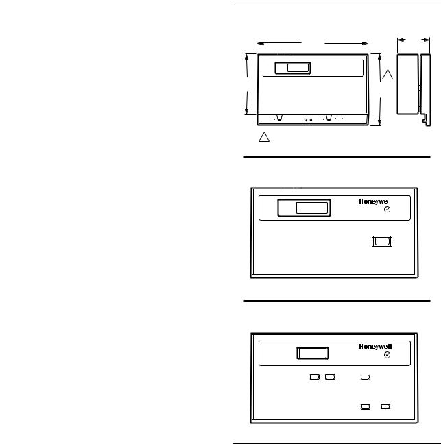
•T7300B is a fully configurable programmable commercial thermostat with the 3-HOUR OVERRIDE key in the cover, to be used with a Q7300 Subbase. (See Fig. 2).
•T7300C is a fully configurable programmable commercial thermostat with limited access cover for easy programming. Cover includes Set Heat, Set Cool, Warmer, Cooler and Occupied/Unoccupied keys. Use with Q7300 Subbase. (See Fig. 3).
Q7300 SUBBASE
Q7300 Subbases provide features listed in Table 1.
TABLE 1—Q7300 SUBBASE FEATURES.
|
|
|
|
|
|
|
|
|
|
Fan |
|
|
|
Model |
System Switch |
|
Switch |
LEDs |
Application |
Selectable Output |
Q7300Aa,b |
None |
|
None |
None |
Conventional |
1 heat-1 cool; 1 heat-2 cool |
Q7300B |
Heat-Off-Cool-Auto |
|
Auto-On |
|
|
2 heat-1 cool; 2 heat-2 cool |
Q7300C |
Em. Ht.-Heat-Off- |
|
|
Em. Ht., |
1 stage heat pump compressor with |
1 heat-1 cool; 2 heat-1 cool |
|
Cool-Auto |
|
|
Aux. Ht. |
auxiliary heat |
|
|
|
|
|
|
2 stage heat pump compressor with |
1 heat-1 cool; 2 heat-1 cool; |
|
|
|
|
|
auxiliary heat |
3 heat-1 cool |
Q7300D |
|
|
|
None |
1 stage heat pump compressor with |
1 heat-1 cool; 2 heat-1 cool |
|
|
|
|
|
auxiliary heat |
|
|
|
|
|
|
2 stage heat pump compressor with |
1 heat-1 cool; 2 heat-1 cool; |
|
|
|
|
|
auxiliary heatc |
3 heat-1 cool |
Q7300E |
None |
|
|
|
Conventional |
1 heat-1 cool; 2 heat-2 cool |
Q7300F |
|
|
None |
Aux. Ht. |
1 stage heat pump compressor with |
1 heat-1 cool; 2 heat-1 cool |
|
|
|
|
|
auxiliary heat |
|
|
|
|
|
|
2 stage heat pump compressor with |
1 heat-1 cool; 2 heat-1 cool; |
|
|
|
|
|
auxiliary heat |
3 heat-1 cool |
Q7300G |
Heat-Off-Cool-Auto |
|
|
None |
Conventional 1 stage heat with |
1 heat-3 cool (fixed) |
|
|
|
|
|
3-stage cool |
|
Q7300L |
None |
|
Auto-On |
Heat Cool |
2 stage heat (ML984 actuator/ |
1 heat-1 cool; 2 heat-1 cool |
|
|
|
|
|
V5013 Valve) 1 stage cool |
|
aSelect models do not have auxiliary relay output. The auxiliary relay output is used with an ecomonomizer for minimum position control based on programmed time schedule. Can also be used for switching other external equipment.
bQ7300A1000 model configures for 1 heat-1 cool only (fixed).
cUses conventional terminal designations. Compressor changeover is controlled by the heat pump equipment.
Ordering Information
When purchasing replacement and modernization products from your TRADELINE® wholesaler or distributor, refer to the Tradeline
Catalog or price sheets for complete ordering number, or specify— |
|
|
1. |
Order number. |
3. Order additional system components and system accessories |
2. |
Accessories, if desired. |
separately. |
If you have additional questions, need further information, or would like to comment on our products or services, please write or phone:
1.Your local Home and Building Control Sales Office (please check the white pages of your phone directory).
2.Home and Building Control Customer Relations Honeywell, 1885 Douglas Drive North Minneapolis, Minnesota 55422-4386
In Canada—Honeywell Limited/Honeywell Limitée, 35 Dynamic Drive, Scarborough, Ontario M1V 4Z9. International Sales and Service Offices in all principal cities of the world. Manufacturing in Australia, Canada, Finland, France, Germany, Japan, Mexico, Netherlands, Spain, Taiwan, United Kingdom, U.S.A.
63-4038—7 |
2 |
THERMOSTAT
ELECTRICAL RATING: 24 to 30 Vac, 50/60 Hz. SYSTEM CURRENT DRAW: 6 VA maximum at 30 Vac,
50 or 60 Hz.
OUTPUT RELAY DRAW: See Table 2.
TABLE 2—MAXIMUM AMPS AT 30 VAC.
|
|
|
Relay |
Running (A) |
Inrush (A) |
Fan |
1.6 |
3.5 |
Heat |
1.6 |
3.5 |
Cool |
1.6 |
7.5 |
Auxillary (Economizer) |
1.6 |
3.5 |
TEMPERATURE:
Ratings:
Ambient: 40°F to 110°F (4°C to 43°C). Shipping: -30°F to +150°F (-34°C to +65°C).
Display Accuracy: ±1°F (±1°C). Setpoint:
Range: 45°F to 95°F (7°C to 35°C). Differential: 2°F (1°C).
Default Settings: See Table 3.
TABLE 3—DEFAULT SETPOINTS.
|
|
|
Control |
Occupied |
Unoccupied |
Heating |
68°F (20°C) |
55°F (13°C) |
Cooling |
78°F (26°C) |
90°F (32°C) |
REMOTE SENSOR WIRING TEMPERATURE OFFSET: Temperature offset occurs with 500 ft (157m) to 1000 ft (305m) of 2-wire cable. See Table 4.
TABLE 4—TEMPERATURE OFFSET.
|
|
|
|
Temperature |
|
|
|
Range |
18 AWG |
20 AWG |
22 AWG |
50-90°F |
-0.4°F |
-0.7°F |
-1.0°F |
10-32°C |
-0.3°C |
-0.4°C |
-0.6°C |
MINIMUM STAGE OPERATION TIME: Conventional Heat: Two minutes On or Off. Compressor: Two minutes On and four minutes Off.
HUMIDITY RATINGS: 5% to 90% RH, noncondensing. CLOCK ACCURACY: ±1 minute per month.
BATTERY BACKUP: Up to 60 hours with fresh 9-volt alkaline battery. Mallory MN11604™ or equivalent.
FINISH: Beige thermostats with brown subbases or Premier White™ thermostats with light gray subbases.
DIMENSIONS: See Fig. 1. T7300 Doors: See Fig. 2.
MOUNTING MEANS: T7200 Thermostat mounts on a wallplate. The T7300 mounts on the Q7300 Subbase. The Q7300 and wallplate mount horizontally on a wall or outlet box with two no. 6 x 32 screws (included).
T7200/T7300/Q7300
SPECIFICATIONS
Fig. 1—Thermostat and subbase dimensions in in. (mm).
8 |
(204) |
1-3/4 |
|
(41) |
|||
|
|
1
4
(102) 4-5/8
(118)
EM. HEAT |
AUX. HEAT |
FAN |
|
AUTO ON |
EM. HEAT HEAT OFF COOL |
M4404
1 T7300/Q7300 ONLY.
Fig. 2—T7300B door.
OCCUPIED • |
|
|
|
|
|
UNOCCUPIED • |
ENVIRONMENTAL |
|
CONT UNOC • |
|
|
3 HR OCCUPIED • |
CONTROL |
|
3 HOUR
OCCUPIED
M4421
Fig. 3—T7300C door.
OCCUPIED •
UNOCCUPIED • |
|
|
ENVIRONMENTAL |
|
|
|
CONTROL |
|
SET |
SET |
WARMER |
TO ADJUST HEAT |
|
|
|
PRESS SET HEAT THEN |
HEAT |
COOL |
|
PRESS WARMER OR COOLER |
|
TO ADJUST COOLING
PRESS SET COOL THEN
PRESS WARMER OR COOLER
FOR AFTER HOURS
PRESS OCCUPIED UNOCCUPIED
FOR BUSINESS HOURS OCCUPIED
PRESS OCCUPIED UNOCCUPIED AGAIN
COOLER UNOCCUPIED
TO ACCESS FULLY PROGRAMMABLE TIME AND TEMPERATURE FEATURES LIFT COVER
M4422
ACCESSORIES:
—229997BU T7300B Conversion Kit. (See Fig. 2).
—229997BY T7300A Conversion Kit. (See cover photo).
—229997CE T7300C Conversion Kit. (See Fig. 3).
—231054AA White Door Assembly for T7300C. (See Fig. 3.
—231055AA White Door Assembly for T7300B. (See Fig. 2).
—231056AA White Door Assembly for T7300A. (See cover photo).
—4074EEP Hardware for door and hinge pin assembly.
3 |
63-4038—7 |

T7200/T7300/Q7300
SPECIFICATIONS • RECYCLING • INSTALLATION
— 4074EFS Bag Assembly (two sheet metal screws and |
— T7147A1002 Remote Temperature Sensor and Over- |
||
two machine screws). |
ride Module. |
||
— 4074EKA Bag Assembly (Allen wrench and four |
— T7147A1010 Remote Temperature Sensor and Over- |
||
Allen head screws). |
ride Module. |
||
— 4074ENE Hinge Pin Assembly. |
— T7147A1028 Remote Temperature Sensor and Over- |
||
— C7400 Enthalpy Sensor. |
ride Module. |
||
— M7415 Damper Actuator. |
— R8222 Switching Relay. |
||
— T675A Temperature Control. |
— W950A System Supervisor. |
||
— T7022A1010 Remote Temperature Sensor. |
— W859D Packaged Economizer. |
||
— T7047C1025 Remote Temperature Sensor. |
— W7459 Economizer Logic Module. |
||
— T7047G1000 Remote Temperature Sensor. |
|
|
|
|
|
|
Recycling Notice |
|
|
M3375 |
|
|
|
|
|
If this control is replacing a control that contains mercury in a sealed tube, do not place your old control in the trash.
Contact your local waste management authority for instructions regarding recycling and the proper disposal of
this control, or of an old control containing mercury in a sealed tube.
Installation
WHEN INSTALLING THIS PRODUCT…
1.Read these instructions carefully. Failure to follow them could damage the product or cause a hazardous condition.
2.Check the ratings given on the product to make sure the product is suitable for your application.
3.Installer must be a trained, experienced service technician.
4.Allow thermostat to warm to room temperature before operating.
5.After installation is complete, check out product operation as provided in these instructions.
 CAUTION
Disconnect power supply before beginning installation to prevent electrical shock or equipment damage.
LOCATION
Thermostat Without Remote-Mounted Temperature Sensor
Install the thermostat about 5 ft (1.5m) above the floor in an area with good air circulation at average temperature. See Fig. 4.
Do not mount the thermostat where it can be affected by:
—drafts or dead spots behind doors, in corners or under cabinets.
—hot or cold air from ducts.
—radiant heat from the sun, fireplace, or appliances.
—concealed pipes and chimneys.
—unheated (uncooled) areas such as an outside wall behind the thermostat.
Thermostat With Remote-Mounted Temperature Sensor(s)
Install the thermostat in an area that is accessible for setting and adjusting the temperature and settings.
Install the remote-mounted sensor(s) about 5 ft (1.5m) above the floor in an area with good air circulation at average temperature. See Fig. 4.
Do not mount the sensor(s) where it can be affected by:
—drafts or dead spots behind doors, in corners or under cabinets.
—hot or cold air from ducts.
—radiant heat from the sun, fireplace, or appliances.
—concealed pipes and chimneys.
—unheated (uncooled) areas such as an outside wall behind the thermostat.
If more than one remote sensor is required, they must be arranged in a temperature averaging network consisting of two, three, four, five, or nine sensors. Instal as shown in Fig. 5-9.
REPLACE AN EXISTING THERMOSTAT OR NEW INSTALLATION
Replace An Existing Thermostat
Turn off all sources of power for the thermostat. Remove any existing wallplate or subbase from the wall. To avoid miswiring later, label or write down each wire color with the letter or number on the wiring terminal as the wire is removed.
63-4038—7 |
4 |

T7200/T7300/Q7300
INSTALLATION
Fig. 4—Location for installing thermostat or remote-mounted sensor.
YES
NO
NO
5 FEET
[1.5 METERS]
NO
M4385
Fig. 5—Two T7047G1000 Sensors providing a temperature averaging network for a T7300/ Q7300 Thermostat/Subbase.
|
Q7300 |
T |
T |
T7047G1000 |
T7047G1000 |
T |
T |
T |
T |
Fig. 7—Four T7047C1025 Sensors providing a temperature averaging network for a T7300/ Q7300 Thermostat /Subbase.
|
|
Q7300 |
|
|
T |
T |
|
T7047C |
|
T7047C |
|
T |
T |
T |
T |
M3421
Fig. 6—Two T7047C1025 and one T7047G1000 |
T7047C |
|
|
T7047C |
|
Sensors providing a temperature averaging |
|
|
|
|
|
network for a T7300/Q7300 Thermostat/Subbase. |
T |
T |
|
T |
T |
|
|
|
|
|
|
Q7300 |
|
T |
T |
|
|
|
M3420 |
T7047C |
|
|
T |
T |
|
|
T7047G1000 |
|
T7047C |
T |
T |
T |
T |
|
|
|
M3418 |
5 |
63-4038—7 |

T7200/T7300/Q7300
INSTALLATION
Fig. 8—Five T7047G1000 Sensors providing a temperature averaging network for a T7300/ Q7300 Thermostat/Subbase.
|
Q7300 |
|
|
|
|
|
T |
T |
|
|
|
T7047G |
|
T7047G |
|
|
|
T |
T |
T |
T |
T7047G |
|
T7047G |
|
T7047G |
|
T |
T |
|
|
|
|
||
T |
T |
T |
T |
|
|
|
|
|
|
|
M3422 |
Fig. 9—Nine T7047C1025 Sensors providing a temperature averaging network for a T7300/ Q7300 Thermostat/Subbase.
|
|
Q7300 |
|
|
|
|
|
T |
T |
|
|
T7047C |
|
T7047C |
|
T7047C |
|
T |
T |
T |
T |
T |
T |
T7047C |
|
T7047C |
|
T7047C |
|
T |
T |
T |
T |
T |
T |
T7047C |
|
T7047C |
|
T7047C |
|
T |
T |
T |
T |
T |
T |
M3419
New Installation
Run cable to a hole at the selected wall location for the thermostat and pull about 3 in. (76 mm) of wire through the opening. Color-coded, 18-gauge thermostat cable with at least one conductor for each wiring terminal is recommended. Good service practice recommends selecting a cable with one or two extra conductors than the immediate application requires.
If using remote temperature sensor(s) or LAN override switch module, refer to the mounting instructions included with the device for wiring cable requirements. Route cable away from sources of electrical noise.
IMPORTANT: The remote sensor(s) or override switch wires must be in a shielded cable if bundled or placed in the same conduit with the cooling control wires. Earth ground the shield at the thermostat.
SET Q7300 SUBBASE DIP SWITCHES
NOTE: Subbase dip switches are not available on the T7200 Wallplate.
The Q7300 Subbase provides the T7300 Thermostat with an interface to the single zone HVAC system. See Table 5 for DIP switch settings. The subbase DIP switches are located on the front and to the right of the wiring terminals. See Fig. 10. Set the DIP switches for the system being controlled.
TABLE 5—SUBBASE DIP SWITCH SETTINGS.
|
|
|
Switch |
Setting |
Function |
1a |
OFF |
1 stage heat |
|
ONb |
2 stage heat |
2a |
OFF |
1 stage cool |
|
ONb |
2 stage cool |
3 |
OFF |
Proportional control (allows droop) |
|
ONb |
Proportional plus integral (P+I) |
|
|
control (droopless) |
4c |
ONb |
Energizes fan on cool only |
|
OFF |
Energizes fan on heat and cool |
5 |
ONb |
Use internal sensor |
|
OFF |
Use remote sensor |
aNo effect on 1 heat/1 cool (Q7300A) or 1 heat/3 cool (Q7300G) models.
bFactory setting.
cNo effect on heat pump systems.
MOUNT SUBBASE OR WALLPLATE
The subbase or wallplate can be mounted on a horizontal outlet box or directly on the wall. For an outlet box installation, go to step 3.
63-4038—7 |
6 |

T7200/T7300/Q7300
INSTALLATION
1. For a wall installation, hold subbase or wallplate in position and mark holes for the anchors. See Fig. 4. Wall anchors must be obtained locally. Be careful that the wires do not fall back into the wall opening. Set aside subbase or wallplate.
2.Drill four 3/16 in. (4.8 mm) holes and gently tap anchors into the holes until flush with the wall.
3.Pull wires through the cable opening. See Fig. 11.
Fig. 10—Setting subbase DIP switches.
|
B |
|
|
A3 |
A2 |
A1 |
W2 |
Y2 |
T |
T |
|
1 |
|
|
|
|
|
|
|
|
|
|
|
|
O |
N |
|
|
|
|
|
|
|
|
|
|
|
|
|
1 |
2 |
3 |
4 |
5 |
|
Y1 |
G |
RC |
RH |
|
CA1 |
CA2 |
CA3 |
CA4 |
CA5 |
|
|
|
|
|
|
|
|
LED1 |
LED2 COM |
|
|
|
|
|
|
|
|
|
1 CONFIGURATION OF ILLUSTRATED SWITCH IS: |
|
|
|
|
|
|
||||||||
1 |
– ON |
|
|
|
|
|
|
|
|
|
|
|
|
|
2 |
– OFF |
|
|
|
|
|
|
|
|
|
|
|
|
|
3 |
– OFF |
|
|
|
|
|
|
|
|
|
|
|
|
M4401 |
4 |
– ON |
|
|
|
|
|
|
|
|
|
|
|
|
|
|
|
|
|
|
|
|
|
|
|
|
|
|
||
5 |
– ON |
|
|
|
|
|
|
|
|
|
|
|
|
|
Fig. 11—Installing subbase on outlet box or on wall.
B |
|
|
A3 |
A2 |
A1 |
W2 |
Y2 |
T |
T |
Y1 |
G |
RC |
RH |
|
CA1 |
CA2 |
CA3 |
CA4 |
CA5 |
|
|
|
LED1 |
LED2 COM |
|
|
|
|
|
SHEET METAL
SCREWS
MOUNTING TO WALL BOARD
MACHINE
SCREWS
OR |
|
|
|
|
|
|
|
|
|
B |
|
|
A3 |
A2 |
A1 |
W2 |
Y2 |
T |
T |
Y1 |
G |
RC |
RH |
|
CA1 |
CA2 |
CA3 |
CA4 |
CA5 |
|
|
|
LED1 |
LED2 COM |
|
|
|
|
|
M4410
MOUNTING TO HORIZONTAL 2 X 4 JUNCTION BOX
7 |
63-4038—7 |
T7200/T7300/Q7300
INSTALLATION
4.Secure the subbase or wallplate with the screws provided. Do not fully tighten the screws.
5.Level the subbase or wallplate for appearance only. Leveling is not required for operation. Securely tighten the screws.
WIRE SUBBASE OR WALLPLATE
IMPORTANT: Most equipment manufacturers size system transformers for the equipment installed at the factory. Before connection, be sure that the system transformer can supply the T7200 OR T7300 and Q7300 with adequate power (6 VA). If less than 6 VA is available, install a separate 24 Vac transformer.
 CAUTION
Disconnect power supply before beginning installation to prevent electrical shock or equipment damage.
All wiring must comply with local electrical codes and ordinances.
IMPORTANT: Use 18 gauge, solid-conductor wire whenever possible. If using 18 gauge stranded wire, no more than 10 wires can be used. Do not use larger than 18 gauge wire.
Follow equipment manufacturer’s wiring instructions when available. See Fig. 23-46 for wiring diagrams. To wire subbase, proceed as follows:
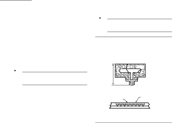
1. Connect the correct wires to the terminals as shown in applicable diagram; the terminal barrier allows straight or wraparound wiring connection. See Fig. 12. A letter code is located near each terminal for identification. Typical terminal designation and wiring connections are listed in Table 6. Connect remote temperature sensor or override switch module.
NOTE: If a remote sensor is used, be sure that the Q7300 DIP switch 5 is placed in the OFF position.
 CAUTION
Never install more than one wire per terminal unless using factory-supplied jumper with spade terminal.
Fig. 12—Barrier configuration. Keep wiring restricted to recessed area surrounding terminals.
FOR STRAIGHT
INSERTION –
STRIP 5/16 in. [8 mm]

 FOR WRAPAROUND – RESTRICT
  STRIP 7/16 in. [11 mm] WIRING TO
THIS AREA
FRONT VIEW OF
TERMINAL AREA
WIRING TO BE BELOW |
TOP SURFACE |
THIS SURFACE |
OF SUBBASE |
CROSS-SECTIONAL VIEW OF |
|
TERMINAL AREA |
M3062 |
2.Firmly tighten each terminal screw. Loose or intermittent wire connections can cause inconsistent system operation.
3.Fit wires as close as possible to the subbase. Push excess wire back into the hole.
4.Plug hole with nonflammable insulation to prevent drafts from affecting the thermostat.
Refer to Fig. 23-46 for typical hookups. When system installation is complete, perform the initial power up procedure in the Checkout section.
63-4038—7 |
8 |
|
|
|
|
|
T7200/T7300/Q7300 |
||
|
|
|
|
|
|
|
|
|
|
|
|
|
INSTALLATION |
||
|
|
TABLE 6—TERMINAL DESIGNATIONS. |
|
|
|
|
|
|
|
|
|
|
|
|
|
Standard |
Alternate |
|
|
|
|
|
|
Terminal |
Designations Or |
|
|
|
|
|
|
Designation |
Customer Specials |
Typical Connection |
Function |
Terminal Type |
|
||
B |
|
Heating damper motor; changeover valve/relay |
Output |
24 Vac powered contact |
|
|
|
|
|
|
|
|
|
||
E |
K |
Emergency heat relay |
Output |
24 Vac powered contact |
|
|
|
G |
F |
Fan relay coil |
Output |
24 Vac powered contact |
|
|
|
O |
R |
Cooling damper motor; changeover valve/relay |
Output |
24 Vac powered contact |
|
|
|
|
|
|
|
|
|
|
|
R |
V |
Power connection to transformer (internally |
Input |
|
|
|
|
|
|
connected for heating and cooling) |
|
|
|
|
|
RC |
|
Power connection to cooling transformer |
Input |
|
|
|
|
|
|
|
|
|
|
|
|
RH |
|
Power connection to heating transformer |
Input |
|
|
|
|
W1 |
H1, R3 |
Stage 1 heating control |
Output |
24 Vac powered contact |
|
|
|
W2 |
H2, Y, R4 |
Stage 2 heating control |
Output |
24 Vac powered contact |
|
|
|
|
|
|
|
|
|
||
W3 |
|
Stage 3 heating control |
Output |
24 Vac powered contact |
|
|
|
Y1 |
C1, M |
Stage 1 cooling control |
Output |
24 Vac powered contact |
|
|
|
Y2 |
C2 |
Stage 2 cooling control |
Output |
24 Vac powered contact |
|
|
|
|
|
|
|
|
|
||
Y3a |
|
Stage 3 cooling controla |
Output |
24 Vac powered contact |
|
|
|
X |
X1,X2,C |
Common connection |
Input |
|
|
|
|
|
|
|
|
|
|
|
|
T |
|
Remote sensorb |
Input |
|
|
|
|
|
L, C, H |
HSII control panel |
|
|
|
|
|
|
|
|
|
|
|
|
|
|
O |
Momentary circuit, changeover |
|
|
|
|
|
LED1, |
A,A1,A2,Z,C,L |
LEDs |
Annunciation |
|
|
|
|
LED2, COM |
|
|
|
|
|
|
|
|
|
|
|
|
|
|
|
|
T |
External temperature readout, T relay |
|
|
|
|
|
|
R1, R2 |
LO and HI speed fan relays |
|
|
|
|
|
|
RS |
Cooling contactor |
|
|
|
|
|
|
|
|
|
|
|
|
|
Y |
M |
Compressor contactor |
|
|
|
|
|
A1, A2, A3 |
|
Auxiliary relay |
Output |
Dry contact |
|
|
|
CA1-CA5 |
|
Remote overrideb |
Input |
Low power |
|
|
|
aQ7300G only.
bShielded cable can be required in some installations where electrical interference (noise) can cause control problems.
SET THERMOSTAT DIP SWITCHES
The thermostat DIP switches provide the thermostat with an interface to the single zone HVAC system. See Table 7 for DIP switch settings. The thermostat DIP switches are located on the back of the thermostat. See Fig. 13. Set the DIP switches for the desired thermostat features and the system being controlled.
IMPORTANT: The thermostat configuration must match the application, or the control logic will not function properly.
TABLE 7—THERMOSTAT DIP SWITCH SETTINGS
|
|
|
Switch |
Setting |
Function |
1 |
ONa |
°F display |
|
OFF |
°C display |
2 |
ONa |
12 hour clock display |
|
OFF |
24 hour clock display |
3 |
ONa,b |
Intermittent fan operation in occupied |
|
|
period |
|
OFF |
Continuous fan operation in occupied |
|
|
period |
4 |
|
Nonfunctional switch |
5 |
ONa |
Keyboard is used for programming |
|
OFF |
Keyboard disabled, but can be used to |
|
|
review program, perform overrides |
|
|
and make clock changes. |
aFactory setting.
bQ7300B,C,D,E,L: fan switch will override this switch setting.
Q7300A,F,G: no override is available.
9 |
63-4038—7 |
T7200/T7300/Q7300
INSTALLATION
Fig. 13—Setting thermostat DIP switches.
T7300 ONLY |
|
|
|
|
|
||||
HEAT PUMP |
|
|
|
|
CONV |
|
|
|
|
°F - TEMP |
12 HR. TIME |
INT - FAN |
|
ON - KEYBD |
°F - TEMP |
12 HR. TIME |
INT - FAN |
|
- KEYBD |
ON |
45 |
90 |
|
|
|
|
|
|
|
|
|
|
|
|
ON |
45 |
|
|
|
1 |
2 |
3 |
4 |
5 |
|
|
|
|
|
°C 24 |
CON |
|
OFF |
|
|
|
|
|
|
|
|
|
|
|
1 |
2 |
3 |
4 |
5 |
|
|
|
|
|
°C |
24 |
CON |
|
OFF |
M4085A |
|
|
|
|
|
|
|
|
|
Fig. 14—Setting thermostat mini-jumper for conventional or heat pump system.
T7300 ONLY |
|
|
|
|
||||
1 |
|
|
|
|
2 |
|
|
|
HEAT PUMP |
|
|
|
|
CONV |
|
|
|
°F - TEMP |
12 HR. TIME |
INT - FAN |
|
ON - KEYBD |
°F - TEMP |
12 HR. TIME |
INT - FAN |
ON - KEYBD |
ON |
45 |
90 |
|
|
||||
1 |
2 |
3 |
4 |
5 |
||||
|
|
|
|
|
||||
°C 24 |
CON |
|
OFF |
|
|
|
|
|
|
|
|
|
|
|
|
90 |
|
1 ONLY PUT MINI-JUMPER IN THIS POSITION WHEN USING Q7300C,D, OR F SUBBASES.
2 ONLY PUT MINI-JUMPER IN THIS POSITION WHEN USING Q7300A,B,E, OR G SUBBASES. |
M4086A |
|
|
63-4038—7 |
10 |
SET THERMOSTAT MINI-JUMPER
NOTE: This operation must be done prior to installing the batteries. If batteries are installed prior to this operation, remove battery for 15 minutes and begin.
The T7300 is factory-set for conventional system control using the Q7300A,B,E,G. If using with a heat pump and Q7300C,D,F, locate the mini-jumper on the back of the T7300. See Fig. 14. Pull the mini-jumper off the two CONV pins and move to the two HEAT PUMP pins. This changes the thermostat to the heat pump algorithm.
If you wish to change the control of the thermostat because a new subbase has been purchased, remove battery for 15 minutes, change mini-jumper position, and re-install battery.
MOUNT THERMOSTAT
 CAUTION
Always disconnect power supply and remove battery from the T7300 before connecting the ribbon cables to prevent electrical shock and equipment damage.
Use the following procedure to connect the T7300 ribbon cables to the Q7300.
1.Check that the 24 Vac power supply is disconnected from the Q7300.
2.Check that the 9 Vdc battery is not installed in the T7300.
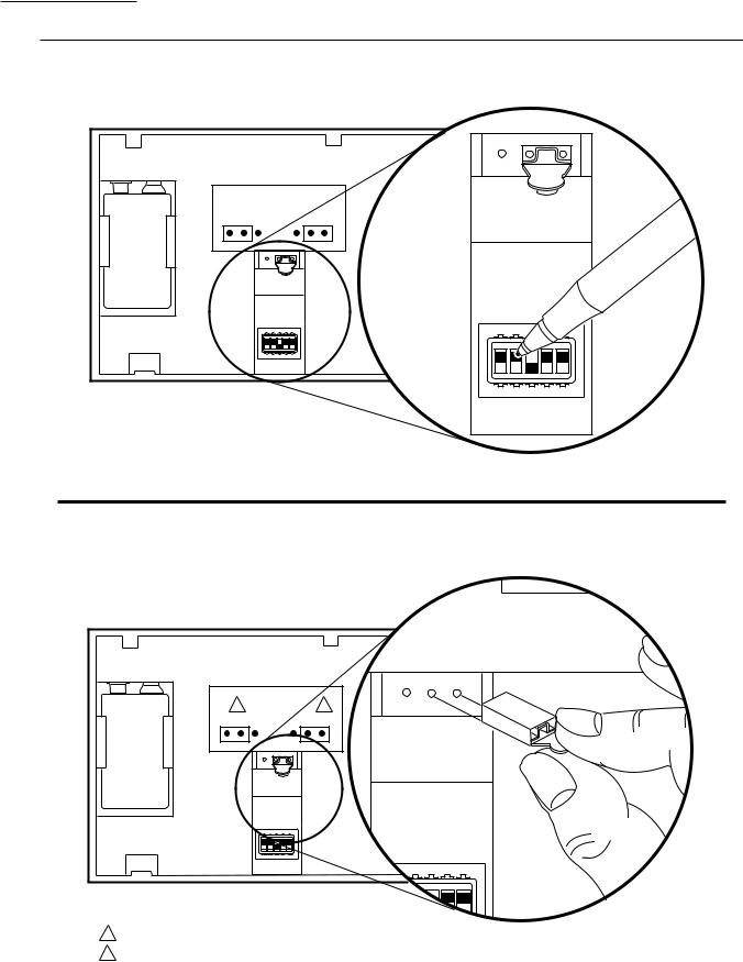
IMPORTANT: First be sure to connect the 12 pin ribbon cable to the Q7300.
3.Connect the 12 pin (larger) ribbon cable to the Q7300. See Fig. 15.
4.Connect the 9 pin (smaller) ribbon cable to the Q7300.
5.If using a 9 Vdc battery, go to the Install Battery Backup section for installation instructions.
Fig. 15—Connecting the pin ribbon cables to the subbase connectors.
9-PIN SUBBASE |
12-PIN SUBBASE |
CONNECTOR |
CONNECTOR |
M4403 |
T7200/T7300/Q7300
INSTALLATION
INSTALL BATTERY (OPTIONAL)
The 9 volt battery is not necessary for the operation of the thermostat, but holds the program during power outages. When the power is restored, the system will resume normal operation. Without the battery, the system will follow the default setpoints. See Table 3. Use the following steps to install a battery:
1.Locate the battery holder on the back of the thermo-
stat.
2.Slide the battery up to the connector until it is firmly seated. See Fig. 16.
NOTE: Observe the polarity when snapping a 9 volt alkaline battery into the holder.
NOTE: The plugs must be firmly seated on the connectors for the thermostat to work properly.
6.Hang the top edge of the thermostat on the subbase hooks. See Fig. 17.
7.Swing down and press on the lower edge until the thermostat snaps in place.
8.Insert and tighten three Allen head screws on the bottom of the thermostat. See Fig. 17.
Fig. 16—Installing optional 9 volt battery.
STEP 1: CONNECT THERMOSTAT
CABLES TO THE SUBBASE.
FIRST CONNECT THE 12 PIN
THEN THE 9 PIN.
BATTERY
STEP 2: SNAP BATTERY INTO PLACE.
SNAPS
STEP 3: SLIDE BATTERY UP TO THE
BATTERY CONNECTOR
UNTIL CONNECTED.
M4408
Fig. 17—Mounting thermostat on subbase.
1
1 DO NOT OVERTIGHTEN SCREWS
M4391
11 |
63-4038—7 |

T7200/T7300/Q7300
PROGRAM THE THERMOSTAT
Program the Thermostat
OVERVIEW
The keyboard is located behind the thermostat flip-up cover. See Fig. 18. There are 16 keys to set, review and modify programmed times and temperatures. The liquid crystal display (LCD) shows day, time or temperature and which programming period is operating.
The thermostat can be set for two occupied and two unoccupied time and temperatures for each day of the week (28 independent settings). The two override keys provide quick temporary programming changes for increased occupant comfort.
IMPORTANT: To program the thermostat, 24 Vac is required (turn on system power) and the keyboard lockout switch (see Fig. 27) must be in the ON-KEYBD position.
Fig. 18—Thermostat programming keys and LCD display.
OCCUPIED • |
|
HEAT |
|
|
|
|
|
UNOCCUPIED • |
11:32 AM |
|
|
|
|
||
CONT UNOC • |
|
|
|
|
|
|
|
3 HR OCCUPIED • |
|
|
|
|
|
|
|
SET |
SET START TIME |
SET TEMPERATURE |
DATA CHANGE |
OVERRIDE |
|||
|
SELECT |
OCCUPIED |
OCCUPIED OCCUPIED |
|
+ |
3 HOUR |
|
CLOCK |
DAY |
START TIME |
HEAT |
COOL |
DISPLAY |
OCCUPIED |
|
|
|
UNOC |
UNOC |
UNOC |
CLEAR |
– |
CONT |
DAY |
COPY |
START TIME |
HEAT |
COOL |
START TIME |
UNOC |
|
|
|
|
|
|
|
|
M4384 |
SET CURRENT TIME/DAY
1.Set the current time by pressing and releasing the CLOCK key once.
2.Press the + or - key until the current time appears on the
LCD.
3.Set the current day by pressing and releasing the DAY key once.
4.Press the + or - key until the current day appears on the
LCD.
NOTE: Su=Sunday; Mo=Monday; Tu=Tuesday; We=
Wednesday; Th=Thursday; Fr=Friday; Sa=Saturday.
SET PROGRAM TIMES
IMPORTANT: The thermostat will remain in occupied mode from the point of initial programming until it encounters the first unoccupied start time. To avoid the unnecessary occupied period following initial programming, set a 12:00 AM unoccupied start time on the thermostat when programmed.
NOTE: The programming times are in intervals of ten minutes; i.e., 8:00, 8:10, 8:20.
1.Press the SELECT DAY key. The display shows the abbreviation for a day.
2.Press and hold the + or - key until the desired day appears.
3.Press the OCCUPIED START TIME key. The program indicator will point to OCCUPIED.
4.Press and hold the + or - key until the desired start time appears.
NOTE: Anytime a start time is not required, press the
CLEAR START TIME key.
5.Press the UNOC START TIME key. The program indicator will point to UNOCCUPIED.
6.Press and hold the + or - key until the desired start time appears.
7.To program a second occupied start time for the selected day, repeat Step 3 until four dashes (----) are displayed or the second start time (if previously programmed) is displayed. Then repeat Step 4.
8.To program a second unoccupied start time for the selected day, repeat Step 5 until four dashes (----) are displayed or the second start time (if previously programmed) is displayed. Then repeat Step 6.
9.Repeat Steps 1 through 8 for each remaining day of the week or refer to the following section, COPY A DAY.
COPY A DAY
1.Press the SELECT DAY key. The display shows the abbreviation for a day.
2.Press and hold the + or - key until the day to be copied from appears.
3.Press the COPY key.
4.Press and hold the + or - key until the day to be copied to appears.
NOTE: The day to be copied from will remain on the display.
5.Press the COPY key a second time to perform the
copy.
6.Repeat Steps 3 to 5 to copy to another day.
SET PROGRAM TEMPERATURE SETPOINTS
NOTE: The setpoint temperature range is 45°F (unoccupied heat) to 95°F (unoccupied cool). The occupied heat setpoint must be at least 2°F less than the occupied cool setpoint.
1. Press the SET TEMPERATURE key (OCCUPIED HEAT, OCCUPIED COOL, UNOC HEAT, or UNOC COOL). The program indicator will point to OCCUPIED or UNOCCUPIED and the LCD will indicate HEAT or COOL.
63-4038—7 |
12 |

2.Press and hold the + or - key until the desired temperature appears.
3.Repeat Steps 1 and 2 until all four temperatures are set.
SET OPERATING DISPLAY
The LCD can show time or temperature. To change the current display, press the DISPLAY key until the desired operating display appears.
CLEAR START TIME
1.Press the SELECT DAY key.
2.Press and hold the + or - key until the desired day appears.
3.Press and hold the OCCUPIED START TIME or the UNOC START TIME key until the time to clear appears.
4.Press and hold the CLEAR START TIME key until the display shows four dashes (----).
NOTE: If there is a second OCCUPIED setting, the start for time this setting will appear instead of four dashes (----).
TEMPORARILY OVERRIDE PROGRAM
There are three overrides available. The 3 hour occupied overrides can be initiated from a remote location or the thermostat. The 3 hour occupied override without + or - keys can also be initiated from the T7300B cover.
NOTE: Pressing the DISPLAY key at anytime will return the thermostat to the program.
3 Hour Occupied
The 3 HOUR OCCUPIED key is used to override the unoccupied program when people need to use the area temporarily (working late, weekends or holidays).
1. Press the 3 HOUR OCCUPIED key to change the unoccupied temperature setting to the occupied setpoint for three hours.
NOTE: The program indicator will point to 3 HR OCCUPIED while the override is in effect.
3 Hour Occupied with + or - Key
T7200/T7300/Q7300
PROGRAM THE THERMOSTAT • CHECKOUT
SET + OR - KEY VALUE
When using the + or - key with the 3 HOUR OCCUPIED key, the + or - key has a preassigned value of 0 to 5°F (default is 0). Use the following steps to check or change the value:
1.Press the 3 HOUR OCCUPIED key. The program indicator will point to 3 HR OCCUPIED.
2.Press the DISPLAY key. The LCD will show a number from 0 to 5.
3.Press the + or - key to change the value.
4.Press the DISPLAY key to return to the program.
Set 3 Hour Occupied Override With + or - Key
The 3 HOUR OCCUPIED key with the + or - key will override the unoccupied program for three hours with the occupied temperature setpoint + the preassigned key value (see Set + or - Key Value section).
1.Press the 3 HOUR OCCUPIED key to change the unoccupied temperature setting to the occupied setpoint for three hours.
2.Press the + key to increase or press the - key to decrease the occupied setpoint by the key value.
EXAMPLE: Unoccupied setpoint is 62°F, occupied setpoint is 70°F and key value is 3°F. Pressing the
3 HOUR OCCUPIED key and the + key will change the setpoint from 62°F to 70°F plus 3°F or 73°F.
Pressing the - key would change the setpoint to 70°F minus 3°F or 67°F.
NOTE: The program indicator will point to 3 HR OCCUPIED while the override is in effect. The LCD will not reflect the key value.
Cont Unoc
The continuous unoccupied override feature holds the setpoint at the unoccupied temperature setpoint until the DISPLAY or CONT UNOC key is pressed. This override is used when the area will be closed for a temporary closing such as a long holiday.
1.Press the CONT UNOC key to hold the temperature at the unoccupied setpoint.
2.Press the CONT UNOC key again to return to the program.
Checkout
OVERVIEW
Check that all wiring is correctly completed and all sensors are installed. The thermostat should be mounted on the wallplate or subbase. If the thermostat has not been programmed, when the power is first turned on, the LCD will show four dashes (----). Without programming, the thermostat will operate from default temperature setpoints (see OPERATION section).
NOTE: It is helpful to program the thermostat before using the Checkout procedure. Refer to the Programming section to set a program.
If the display has two dashes and a degree sign (--°), wait sixty seconds and press the DISPLAY key twice. If the display does not change or is blank, refer to the Troubleshooting section.
TEST MODE
The thermostat has a test mode that aids the installer in performing the checkout. The test mode overrides the minimum on and off times so the checkout can be quickly performed. Press the CLOCK and DAY keys at the same time to start the test mode. All the display segments will appear. See Fig. 19
13 |
63-4038—7 |

T7200/T7300/Q7300
CHECKOUT
 CAUTION
Do not use the test mode for longer than 10 minutes. The test mode overrides the minimum on and off times that protect the system. Equipment damage can result if the thermostat remains in the test mode.
Fig. 19—All segments on display.
AM |
COMM |
TEST MODE |
HEAT |
INDICATOR |
|
PM |
● ● ● |
|
SU MO TU WE TH FR SA |
COOL |
|
BATT |
M4415 |
|
|
|
To discontinue the test mode at any time, press the CLOCK and DAY keys at the same time. The Test Mode Indicators will no longer show on the screen.
HEAT
NOTE: When the thermostat is used with a subbase with subbase and fan switches, set the switches to AUTO.
1.Press the CLOCK and DAY keys at the same time. This starts the test mode.
2.Press the DISPLAY key. See Fig. 20.
Fig. 20—Display when starting test sequence.
|
COMM |
AM |
HEAT |
|
● ● ● |
SU |
COOL |
BATT |
|
|
M4418 |
3.Press the OCCUPIED HEAT key.
4.Press the + key to raise the setpoint 5°F (3°C) above
the room temperature. The heating should start (both stages if multistage), and the fan should run (may be a short delay on forced air systems).
NOTE: It can be necessary to change the OCCUPIED COOL setpoint. However, be aware that OCCUPIED HEAT and OCCUPIED COOL setpoints must have a 2°F difference.
5.Press the OCCUPIED HEAT key.
6.Press the - key to lower the setpoint 5°F (3°C) below
the room temperature. The heating should shut off, followed by the fan shutoff.
When the thermostat has a system switch, move the switch to the HEAT position and repeat steps 3 through 6.
COOL
Move switch to auto.
 CAUTION
Do not operate cooling if outdoor temperature is below 50°F (10°C). Refer to the manufacturer
recommendations.
NOTE: When cooling setting changes, thermostat will wait up to five minutes before turning on the cooling equipment. This delay is to protect the compressor.
1.Press the OCCUPIED COOL key.
2.Press the - key to lower the setpoint 5°F (3°C) below
the room temperature. The cooling should start (both stages if multistage), and the fan should run.
NOTE: It can be necessary to change the OCCUPIED HEAT setpoint. However, be aware that the OCCUPIED HEAT and OCCUPIED COOL setpoints must have a 2°F difference.
3.Press the OCCUPIED COOL key.
4.Press the + key to raise the setpoint 5°F (3°C) above
the room temperature. The cooling and fan should shut off. When the thermostat has a system switch, move the switch to the COOL position and repeat Steps 1 through 4. Move the system switch to the OFF position. All heating
or cooling should stop.
FAN Thermostat
Fan Switch (located on the back of the thermostat):
—CON: Fan operates continuously in the occupied mode.
—INT-FAN: Fan operates directly with the thermostat call for heating or cooling in the occupied mode.
Subbase
NOTE: Subbase fan switch overrides the thermostat fan switch.
Subbase Dip Switch No. 4:
—ON: Fan operates only with cool.
—OFF: Fan operates with heat and cool. Q7300E Fan Switch:
—ON: Fan operates continuously.
—AUTO: Fan operates directly with the thermostat call for heating or cooling.
IMPORTANT:Press theCLOCK and DAYkeys atthe same time to discontinue the test mode. The Test Mode Indicators will no longer show on the screen. See Fig. 19.
63-4038—7 |
14 |

T7200/T7300 RELAY LOGIC
The T7300 contains three switching relays. When the mini-jumper is set for conventional applications, the relays control first stage cooling, first stage heating, and fan. When the mini-jumper is set for heat pump applications, the relays control the heat pump compressor, auxiliary heat, and fan. Because of this change in switching logic, it is important to use Q7300C,D, or F subbases when the T7300 is set for heat pump applications and use Q7300A,B,E,G subbases when the T7300 is set for conventional applications.
The T7200A Relay Logic is for conventional applications. The T7300B Relay Logic is for heat pump applications.
T7200/T7300 AND CONVENTIONAL THERMOSTATS
P+I Control
The T7200/T7300 microprocessor based control requires that the user understands temperature control and thermostat performance. A conventional electromechanical or electronic thermostat does not control temperature precisely at setpoint. Typically, there is an offset (droop) in the control point as the system load changes. This is a phenomenon that most people in the industry know and accept. Many factors contribute to offset including switch differential, thermal lag, overshoot, cycle rates and system load.
The thermostat microprocessor simultaneously gathers, compares and computes data. Using this data, it controls a wide variety of functions. The special proprietary algorithm (program) in the thermostat eliminates the factors causing offset. This makes temperature control more accurate than the conventional electromechanical or electronic thermostats. The temperature control algorithm is called proportional plus integral (P+I) control.
The thermostat sensor, located on the thermostat or remote, senses the current space temperature. The proportional error is calculated by comparing the sensed temperature to the programmed setpoint. The deviation from the setpoint is the proportional error.
The thermostat also determines integral error, which is a deviation based on the length of error time. The sum of the two errors is the (P+I) error. The cycle rate used to reach and maintain the setpoint temperature is computed using the P+I. The addition of the integral error is what differentiates the thermostat from many other electronic and electromechanical thermostats. See Fig. 21.
T7200/T7300/Q7300
OPERATION
Operation
Fig. 21—Proportional temperature control versus P+I temperature control.
|
|
|
|
|
|
|
|
|
THERMOSTAT |
|
|
|
||||
|
|
|
|
|
|
|
|
|
COOL SETPOINT |
|
|
|
|
|||
|
|
|
|
|
|
PROPORTIONAL COOL |
|
|
|
|||||||
|
|
|
|
|
|
CONTROL POINT |
|
|
|
|
|
|
|
|
||
TEMPERATURE |
|
|
|
P+I CONTROL |
|
|
|
|
|
|
|
|
||||
|
|
|
POINT |
|
|
|
P+I CONTROL POINT |
|
|
|
||||||
|
|
|
|
|
|
|
|
|
|
|||||||
|
|
|
|
|
|
|
|
|
|
|
|
|||||
|
|
|
|
|
|
|
|
|
|
|
|
|||||
|
|
|
|
|
|
PROPORTIONAL HEAT |
|
|
|
|||||||
|
|
|
|
|
|
CONTROL POINT |
|
|
|
|
|
|
|
|
||
|
|
|
THERMOSTAT |
|
|
|
|
|
|
|
|
|||||
|
|
|
|
|
|
|
|
|
|
|
||||||
|
|
|
HEAT SETPOINT |
|
|
|
|
|
|
|
|
|||||
|
|
|
|
HEATING |
|
|
|
COOLING |
|
|
|
|
|
|||
|
|
|
|
|
|
|
|
|
|
|
|
|||||
|
|
|
|
|
|
|
|
|
|
|
|
|
|
|
|
|
|
|
|
|
|
|
|
|
|
|
|
|
|
|
|
|
|
100 |
50 |
0 |
50 |
|
|
100 |
||||||||||
|
|
|
|
|
|
|
PERCENT LOAD |
M4414 |
||||||||
|
|
|
|
|
|
|
|
|
|
|
|
|
|
|||
|
|
|
|
|
|
|
|
|
|
|
|
|
|
|
|
|
While the thermostat is designed to eliminate droop, allowing droop can be desirable in applications where building visitors are dressed for the weather and their stays are brief. Examples of these applications include fast food restaurants and convenience stores. The droopless feature of the thermostat can be overridden by placing the droop/ droopless select switch located on the subbase in the OFF position. This removes the integral calculation from the thermostat control scheme, allowing only the proportional control to occur.
EQUIPMENT PROTECTION
As part of the operational sequence, the T7200/T7300 microprocessor also incorporates minimum On and Off times for all heating and cooling stages. Minimum On and Off times assure that rapid cycling of equipment will not occur, extending equipment life. Minimum On/Off times for compressor stages are two minutes On and four minutes Off. Minimum On/Off times for heat (electric resistive or gas) are two minutes.
T7200/T7300 THERMOSTAT OPERATION Startup
When power to the thermostat is turned on, a startup and initialization program begins. The startup takes place after total loss of power (24 Vac and battery backup). At this time, the system default values are put into memory (re-
placing the user program that was lost). Default values are heating 68°F (20°C) and cooling 78°F (26°C) for the occu-
pied modes. Unoccupied default values are heating 55°F (13°C) and cooling 90°F (32°C).
15 |
63-4038—7 |
 Loading...