


T7300F/Q7300H Series 2000 Commercial
Thermostats and Communicating
Subbases
|
Contents |
INTRODUCTION ........................................................................................................................... |
3 |
Description of Devices ....................................................................................... |
3 |
Control Application ............................................................................................. |
3 |
Control Provided................................................................................................. |
4 |
Product Names .................................................................................................. |
4 |
Products Covered............................................................................................... |
5 |
Organization of Manual ...................................................................................... |
5 |
Applicable Literature .......................................................................................... |
6 |
Agency Listings .................................................................................................. |
6 |
Abbreviations and Definitions............................................................................. |
6 |
CONSTRUCTION ........................................................................................................................... |
7 |
Performance Specifications ............................................................................... |
8 |
Input/Output Summary .................................................................................. |
8 |
Communications............................................................................................ |
9 |
LonMark® Functional Profile .............................................................................. |
10 |
Configurations .................................................................................................... |
10 |
General.......................................................................................................... |
10 |
APPLICATION STEPS ........................................................................................................................... |
11 |
Overview ............................................................................................................ |
11 |
Step 1. Plan The System.................................................................................... |
11 |
Step 2. Determine Required Network Devices................................................... |
12 |
Step 3. Lay Out Communications and Power Wiring ......................................... |
12 |
LonWorks® Bus Layout ................................................................................ |
12 |
Cable Termination ......................................................................................... |
14 |
Singly Terminated Network Segment ....................................................... |
14 |
Doubly Terminated Daisy-chain Network Segment .................................. |
15 |
Wiring Details ................................................................................................ |
15 |
Step 4. Prepare Wiring Diagrams ...................................................................... |
15 |
General Considerations................................................................................. |
18 |
Step 5. Order Equipment.................................................................................... |
19 |
Step 6. Configure T7300F/Q7300H.................................................................... |
20 |
Step 7. Troubleshooting ..................................................................................... |
20 |
APPENDIX A ........................................................................................................................... |
20 |
Sequence of Operations.................................................................................... |
20 |
USER ADDRESS |
|
NETWORK VARIABLES |
|
See form number 63-4366, Q7300 Communicating Subbase System Integration |
|
User Address Manual. |
|
LonWorks®, LonTalk®, LonMark® and Excel LonSpec™ are U.S. registered trademarks of Echelon® Corporation.
®U.S. Registered Trademark
Copyright © 1998 Honeywell Inc. • All Rights Reserved
634365

T7300F/Q7300H SERIES 2000 COMMERCIAL THERMOSTATS AND COMMUNICATING SUBBASES
LIST OF FIGURES |
|
Fig. 1. Typical T7300F/Q7300H LonWorks® network diagram.......................... |
3 |
Fig. 2. Typical T7300F/Q7300H application....................................................... |
4 |
Fig. 3. T7300F/Q7300H dimensions in in. (mm). ............................................... |
8 |
Fig. 4. Functional Profile Number 8060¾LonMark® Thermostat Object |
|
(Type 09) (Thermostat profile variables not used are grayed). ..................... |
10 |
Fig. 5. Connecting personal computer to LonWorks® Bus. ............................... |
11 |
Fig. 6. Typical topology for T7300F/Q7300H devices in |
|
LonWorks® network..................................................................................... |
13 |
Fig. 7. Wiring layout for two doubly terminated LonWorks® Bus segments. ..... |
13 |
Fig. 8. Wiring layout for one doubly terminated daisy-chain |
|
LonWorks® Bus segment. ............................................................................ |
14 |
Fig. 9. Singly terminated LonWorksÒ Bus termination module. ........................ |
14 |
Fig. 10. Doubly terminated LonWorks® Bus termination modules. ................... |
15 |
Fig. 11. Proper wiring technique. ....................................................................... |
15 |
Fig. 12. Ferrite core wires from Q7300H to digital inputs and outputs. .............. |
15 |
Fig. 13. Typical hookup of T7300F/Q7300H in three-stage heat, |
|
two-stage cool heat pump system................................................................. |
16 |
Fig. 14. Typical hookup of T7300F/Q7300H in three-stage heat, |
|
two-stage cool heat pump system................................................................. |
16 |
Fig. 15. Typical hookup of T7300F/Q7300H in three-stage heat, |
|
three-stage cool conventional system. .......................................................... |
17 |
Fig. 16. Typical hookup of T7300F/Q7300H in two-stage heat, |
|
one-stage cool conventional system. ............................................................ |
17 |
LIST OF TABLES |
|
Table 1. Additional Products. ............................................................................. |
5 |
Table 2. Terminal descriptions and conditions................................................... |
9 |
Table 3. Application Steps. ................................................................................ |
11 |
Table 4. LonWorks® Configuration Rules and Device Node Numbers.............. |
12 |
Table 5. Field Wiring Reference Table ............................................................... |
18 |
Table 6. Ordering Information. ........................................................................... |
19 |
63-4365 |
2 |
T7300F/Q7300H SERIES 2000 COMMERCIAL THERMOSTATS AND COMMUNICATING SUBBASES
INTRODUCTION
Description of Devices
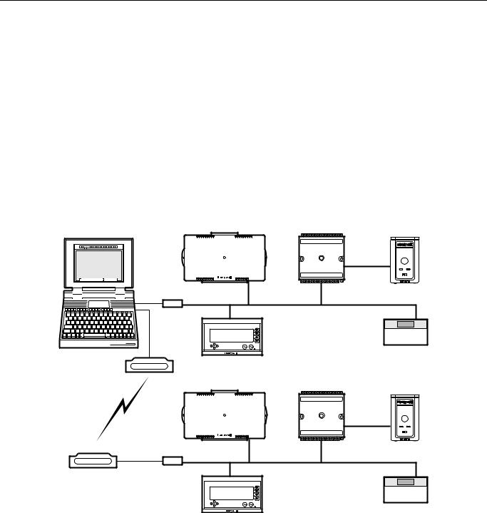
The Q7300H Subbase is a LonMark® certified device that provides networking capability for the T7300F Thermostat in a LonWorks® system using a transformer-coupled Free Topology Transceiver (FTT). See Fig. 1.
The T7300F/Q7300H communicates with all LonMark® devices including the following:
¾Other T7300F/Q7300H Commercial Thermostat/Communicating Subbases.
—Excel 15 S7760A Command Display.
—Excel 10 W7750A,B Constant Volume Air Handler Unit (CVAHU) Controller.
—Excel 15 W7760A Building Manager.
—Excel 10 W7761A Remote Input/Output (RIO) Controller.
Control Application
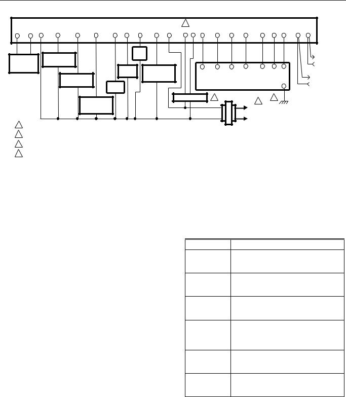
The T7300F/Q7300H Series 2000 Commercial Thermostats and Communicating Subbases control 24 Vac commercial single zone heating, ventilating and air conditioning (HVAC) equipment. In addition, the Q7300H can communicate schedule information and system instructions to other devices in a LonWorks® network. Fig. 2 shows a typical T7300F/Q7300H application in a three-stage heat and two-stage cool heat pump system. For additional T7300F/Q7300H hookups, see Fig. 13, 15, 16.
BUILDING MANAGER |
WALL MODULE |
|||||
NOTEBOOK PC |
1 4 |
8 |
12 |
16 |
|
|
EXCEL 15 |
|
|
|
EXCEL 10 |
||
W7760 |
|
|
|
|
||
|
|
|
|
|
||
|
|
|
|
|
|
CVAHU |
17 |
23 |
30 |
31 |
37 |
44 |
|
RS-232 |
|
|
|
|
|
|
SERIAL |
|
|
|
|
|
|
PORT |
|
|
|
|
|
|
SLTA |
|
|
|
|
|
LonWorks® BUS |
|
|
|
|
S7760 |
T7300 |
|
|
|
|
|
|
||
Back |
Select |
MODEM
RS-232 MODEM SERIAL
PORT
BUILDING MANAGER |
WALL MODULE |
|||||
|
1 4 |
8 |
12 |
16 |
|
|
EXCEL 15 |
|
|
|
EXCEL 10 |
||
W7760 |
|
|
|
|
||
|
|
|
|
|
||
|
|
|
|
|
|
CVAHU |
17 |
23 |
30 |
31 |
37 |
44 |
|
SLTA |
|
|
|
|
S7760 |
LonWorks® BUS |
|
|
|
|
|
T7300 |
|
Back |
Select |
|
M16083B |
Fig. 1. Typical T7300F/Q7300H LonWorks® network diagram.
3 |
63-4365 |
T7300F/Q7300H SERIES 2000 COMMERCIAL THERMOSTATS AND COMMUNICATING SUBBASES
SUBBASE
3
AS AS X |
Y2 |
Y1 |
O |
E G W1 |
B |
R |
A1 A2 C5 |
C4 C3 |
C2 |
C1 T T |
EB EB |
|
|
AUX. |
|
|
|
|
|
|
|
|
DISCHARGE |
COMPRESSOR |
HEAT |
|
|
|
|
|
|
|
LonWorks® |
CONTACTOR 2 |
|
|
|
|
|
|
|
|
||
AIR |
|
|
|
|
|
|
|
|
BUS |
|
|
|
|
|
|
|
|
|
|
||
SENSOR |
FAN |
HEAT |
CA5 |
CA4 |
CA3 |
CA2 |
CA1 |
T |
T |
|
|
RELAY |
CHANGEOVER |
|
|||||||
|
T7147 REMOTE COMFORT ADJUST MODULE |
|
||||||||
|
COMPRESSOR |
VALVE |
LonWorks® |
|||||||
|
CONTACTOR 1 |
|
|
|
|
|
|
GND |
||
|
|
|
|
|
|
|
|
BUS |
||
|
EM. HT. |
|
|
|
|
|
|
|
|
|
|
RELAY |
|
|
|
|
|
|
|
|
|
ECONOMIZER |
2 |
4 |
COOL |
|
1 |
CHANGEOVER |
|
L1 |
VALVE |
|
(HOT) |
|
|
L2 |
1 POWER SUPPLY. PROVIDE DISCONNECT MEANS AND OVERLOAD PROTECTION AS REQUIRED. |
TRANSFORMER |
|
2 |
USE ECONOMIZER INSTRUCTIONS FOR INSTALLATION INSTRUCTIONS. |
|
3 |
USE A1 AND A2 WHEN CONTACTS ARE NORMALLY CLOSED IN OCCUPIED MODE. |
M16056 |
4 CONNECT GND TO EARTH GROUND.
Fig. 2. Typical T7300F/Q7300H application.
Communicating subbases for T7300F Thermostats add value by allowing remote-site access—via telephone lines—for diagnostics, maintenance and monitoring. In addition, the T7300F can act as the user interface for onsite Excel 10 Controllers (after initial installation with Excel LonSpec™) without the need for a personal computer workstation. Through the T7300F/Q7300H Thermostat/Communicating Subbase, a building operator can control Excel 10 devices by setting occupancy schedules, setpoints and additional features.
Control Provided
The Q7300H communicates with other network devices, or nodes, for the purpose of sharing data. Through the network, the T7300F/Q7300H sets and deletes schedules. Schedules can be bypassed by selecting Continuous Unoccupied or Temporary Override. By using network messaging, the Q7300H sets fan operation (ON, AUTO) and system mode (HEAT, COOL, AUTO, OFF, EM HEAT) designated by a remote T7300F. Schedules can be programmed for seven days with four designated periods per day; Occupied 1, Occupied 2, Unoccupied 1 and Unoccupied 2. In external schedule mode, the T7300F changes occupancy through a network-based scheduler. In local schedule mode, the T7300F changes occupancy through an internal scheduler. If the external schedule is not periodically updated, the T7300F defaults to the local schedule.
The T7300F/Q7300H is also able to provide time of day, temporary setpoint, bypass status and additional information to multiple Excel 10 devices by sending instructions from one T7300F/Q7300H to the Excel 10 devices. When the T7300F is configured to schedule temporary setpoint and effective bypass information for other devices, certain restrictions apply such as:
—When the T7300F is scheduling temporary setpoints for Excel 10 devices, the Excel 10 cannot adjust setpoints using the T7770 wall module.
—When the T7300F is providing effective bypass information to Excel 10 devices, the Excel 10 cannot change the bypass status using the T7770 wall module.
Product Names
When combined with the T7300F Series 2000 Commercial Thermostat, the Q7300H Communicating Subbase communicates with other devices in a LonWorks® network. The thermostat and subbase are available in the following models:
Part Number |
Product Description |
Q7300H2003 Communicating subbase with O and B terminals for three-stage heat, two-stage cool heat pump system.
Q7300H2011 Communicating subbase without O and B terminals for three-stage heat, twostage cool heat pump system.
Q7300H2029 Communicating subbase for three-stage heat, three-stage cool conventional system.
Q7300H2037 Communicating subbase for two-stage heat, one-stage cool conventional system with valve two-position heat output.
T7300F2002 Series 2000 Commercial Electronic Thermostat without system and fan switching.
T7300F2010 Series 2000 Commercial Electronic Thermostat with system and fan switching.
63-4365 |
4 |

T7300F/Q7300H SERIES 2000 COMMERCIAL THERMOSTATS AND COMMUNICATING SUBBASES
Products Covered |
Organization of Manual |
This System Engineering manual describes how to apply the T7300F Thermostat and Q7300H Communicating Subbase and related accessories to typical applications. Devices include:
T7300F Series 2000 Commercial Thermostat. Q7300H Series 2000 Communicating Subbase. Excel 15 W7760A Building Manager.
Excel 10 Controllers, as follows:
W7750A,B Constant Volume Air Handler Unit (CVAHU) Controller.
W7761 Remote Input/Output (RIO) Controller.
Other products: Q7751A,B Bus Router.
Q7760A Serial LonTalk® Adapter. Q7740A,B FTT Repeaters. 209541B FTT Termination Module.
See Table 1 for additional products.
This manual is divided into four basic sections:
1.Introduction. Provides an overview of the T7300F/Q7300H, discusses related devices, lists additional literature, and provides a glossary of abbreviation and terms.
2.Construction. Describes T7300F/Q7300H features, network connections and dimensions.
3.Application Steps. A step-by-step procedure that provides the information necessary to plan and lay out the T7300F/Q7300H application and accurately order materials.
4.Appendix. Appendix A provides a sequence of operations for configuring network controllers.
The organization of the manual assumes a project is being engineered from start to finish. If you are changing an existing system, refer to the Table of Contents for relevant sections.
Table 1. Additional Products.
Part Number |
Product Description |
Comments |
|
|
|
R8242A |
Contactor, 24 Vac coil, DPDT. |
— |
|
|
|
AT72D, AT88A, etc. |
Transformers. |
— |
|
|
|
4074EYD |
Wallplate for T7770 Wall Modules. |
For covering an existing hole in a |
|
|
wall. |
|
|
|
— |
Serial Interface Cable, male DB-9 to female DB-9 or |
Obtain locally from any computer |
|
female DB-25. |
hardware vendor. |
|
|
|
Honeywell (US only) |
LonWorks® Bus (plenum): 22 AWG (0.325 sq mm) |
Level IV, 140°F (60°C) rating. |
AK3791 (one twisted pair) |
twisted pair solid conductor, nonshielded or Echelon® |
|
AK3792 (two twisted pairs). |
approved shielded cable. |
|
|
|
|
Honeywell (US only) |
LonWorks® Bus (nonplenum): 22 AWG (0.325 sq mm) |
Level IV, 140°F (60°C) rating. |
AK3781 (one twisted pair) |
twisted pair solid conductor, nonshielded or Echelon® |
|
AK3782 (two twisted pairs). |
approved shielded cable. |
|
|
|
|
Honeywell AK3725 (US only), |
Inputs: 18 AWG (1.0 sq mm) five wire cable bundle. |
Standard thermostat wire. |
typical or equivalent. |
|
|
|
|
|
Honeywell AK3752 (US only), |
Outputs/Power: 14 to 18 AWG (2.0 to 1.0 sq mm). |
NEC Class 2, 140°F (60°C) rating. |
typical or equivalent. |
|
|
|
|
|
Honeywell AK3702 (US only), |
18 AWG (1.0 sq mm) twisted pair. |
Non-plenum. |
typical or equivalent. |
|
|
|
|
|
Honeywell AK3712 (US only), |
16 AWG (1.3 sq mm) twisted pair. |
Non-plenum. |
typical or equivalent. |
|
|
|
|
|
Honeywell AK3754 (US only), |
14 AWG (2.0 sq mm) two conductor. |
Non-plenum. |
typical or equivalent. |
|
|
|
|
|
5 |
63-4365 |

T7300F/Q7300H SERIES 2000 COMMERCIAL THERMOSTATS AND COMMUNICATING SUBBASES
Applicable Literature
The following list of documents contains general information related to the T7300F/Q7300H Series 2000 Commercial Thermostats and Communicating Subbases.
Form No. |
Title |
|
|
62-0125 |
T7300F Series 2000 Commercial |
|
Microelectronic Conventional or Heat |
|
Pump Thermostat Installation Instructions |
|
|
62-0155 |
Q7300H Series 2000 Commercial |
|
Thermostat Installation Instructions |
|
|
74-2976 |
Excel LonSpec™ Specification Data |
|
|
74-2977 |
Excel LonSpec™ Software Release |
|
Bulletin |
|
|
74-2937 |
Excel LonSpec™ User’s Guide |
|
|
74-2982 |
Light Commercial Building Solutions |
|
System Specification Data |
|
|
74-2865 |
E-Bus Wiring Guidelines User’s Guide |
|
|
74-2967 |
Excel 15 W7760A Building Manager |
|
Specification Data |
|
|
95-7565 |
Excel 15 W7760A Building Manager |
|
Installation Instructions |
|
|
74-2969 |
Excel 15 W7760A Building Manager |
|
System Engineering |
|
|
74-2956 |
Excel 10 W7750A,B CVAHU Controller |
|
Specification Data |
|
|
95-7521 |
Excel 10 W7750A,B CVAHU Controller |
|
Installation Instructions |
|
|
74-2958 |
Excel 10 W7750A,B CVAHU Controller |
|
System Engineering |
|
|
74-2698 |
Excel 10 W7761A RIO Controller |
|
Specification Data |
|
|
95-7539 |
Excel 10 W7761A RIO Controller |
|
Installation Instructions |
|
|
74-2699 |
Excel 10 W7761A RIO Controller System |
|
Engineering |
|
|
74-2697 |
T7770A, B, C, D, E, F, G Wall Module |
|
Specification Data |
|
|
95-7538 |
T7770A, B, C, D, E, F, G Wall Module |
|
Installation Instructions |
|
|
95-7554 |
209541B Termination Module Installation |
|
Instructions |
|
|
Agency Listings
European Community Mark (CE): Conforms to requirements of European Consortium Standards.
ABBREVIATIONS AND DEFINITIONS
Application—A specific Building Control function.
Binding—The process of logically connecting network variables in one node to network variable(s) in other node(s). Binding is performed by a network management node that writes the binding information into the EEPROM memory of all the neuron's involved. The binding information is saved in the network image of each neuron.
Building Manager—A LonMark® certified device that can be used to monitor and control HVAC equipment and other miscellaneous loads in a distributed network.
Command Display—A device that can be used to monitor and change parameters.
Control Loop—A primitive control function. A type of function in a node that includes processes, loops and programs. A node can contain one or more control loops. (In Excel 10 class devices, the control loop occupies the entire node.)
CVAHU—Excel 10 Constant Volume Air Handler Unit
Controller.
Excel 10s—A family of application - specific HVAC controllers such as the Excel 10 CVAHU and Excel 10 RIO.
HVAC—Heating, Ventilating and Air Conditioning.
I/O—Input/Output.
LonWorks® Network —A data network based on neurons communicating with each other using the LonTalk® protocol.
Mandatory Mechanisms/Objects/Network Variables—
Mandatory mechanisms and network variables that are implemented in all the Excel 10 devices.
NamedObject—Objects that have names are called NamedObjects. These objects are visible on the network as functional independent entities and are accessed by name. Typical examples of NamedObjects are Controllers, ControlLoops and LogicFunction blocks.
Network Management Node—A LonWorks® node that is responsible for configuring the network, installing the nodes, binding the network variables between nodes, and general network diagnostics.
63-4365 |
6 |

T7300F/Q7300H SERIES 2000 COMMERCIAL THERMOSTATS AND COMMUNICATING SUBBASES
Network Variables—A class of variables defined in Neuron C that allows communication over the LonWorks® network to other nodes on the network. An output network variable in one node can be bound to corresponding input network variable(s) in other node(s). Changing the value of the output network variable in one node causes the new value to be automatically communicated to the bound input network variable(s) in other node(s). When an input network variable is updated, an nv_update_occurs event is posted at the receiving node(s) so that the application program can take action based on the change. A network management node that explicitly reads and/or writes the network variable can also poll network variables. Network variables can contain one data field (one or two bytes) or multiple data fields (a structure).
Node—A device implementing layers one through six of the LonTalk® protocol including a Neuron® Chip, transceiver, memory, and support hardware.
Notebook PC—Portable personal computer.
Optional Mechanism/Object/Network Variables—
Optional mechanisms and variables that shall be implemented on an as-needed basis. However, a different mechanism or network variable cannot be implemented if an existing optional mechanism or network variable can perform the same function.
Programmable Controller—A controller that has a variable number of control loops of different types and is user-programmed to execute an application. The user can select the number and type of control loops. The user also has the capability of generating new types of control loops.
Recovery Mode or Recovery Period—The time in unoccupied periods when the temperature control is adjusting the control setpoint so that the space temperature reaches the occupied setpoint when the schedule change occurs.
RIO—Excel 10 Remote Input/Output device.
RTC—Real Time Clock.
Schedule—The structure that defines the occupancy states, setpoints and the time of the changes between these states.
SGPU—Significant Event Notification and Guaranteed
Periodic Update.
SGPUC—Significant Event Notification and Guaranteed Periodic Update with Change Field.
SLTA—Serial LonTalk® Adapter. Adapts the transformer coupled LonTalk® messages to the RS-232 Serial Port.
SNVT—Standard Network Variable Type.
SCPT—Standard Configuration Parameter Type.
CONSTRUCTION
The T7300F Thermostat has a keypad for setting system parameters, a corresponding LCD display and a flip-down keypad cover. The T7300F Thermostat mounts on the Q7300H Subbase.
The Q7300H Communicating Subbase includes LonWorks® Bus terminals and a jack for temporary network connections to a personal computer. A service pin push button provides service messaging to physically locate the device on the LonWorks® network. The subbase mounts horizontally on the wall or on a
2 in. x 4 in. junction box.
Fig. 3 shows T7300F/Q7300H dimensions.
7 |
63-4365 |

T7300F/Q7300H SERIES 2000 COMMERCIAL THERMOSTATS AND COMMUNICATING SUBBASES
 6-11/16 (170)
1/16 (2)
 3-3/16 (77)
 1-3/8 (35)
1-7/8
(47)
4-1/8
(105)
 1-11/16
  (43)
(43)
7-5/16 (186) |
7/8 |
|
|
|
(22) |
|
|
Set Program |
|
Set Temperature |
||
Run |
Occupied |
Unoccupied |
|
Occupied |
Unoccupied |
|
Program |
Day |
|||||
Start Time |
Start Time |
Temp |
Temp |
|||
Temporary |
Set Current |
Clear |
Copy |
|
Heat/Cool |
|
Occupied |
Day/Time |
Start Time |
|
Settings |
||
Continous |
|
|
|
System |
Fan |
|
Unoccupied |
|
|
|
|||
Change
Time/Temp
4-5/8
(117)
M16086A
Fig. 3. T7300F/Q7300H dimensions in in. (mm).
Performance Specifications
Electrical Ratings:
Power: 20 to 30 Vac, 50/60 Hz.
System Current: 6 VA maximum at 30 Vac, 50 or 60 Hz.
Temperature Ratings:
Setpoint Range: Heating: 40°F to 90°F (4°C to 32°C; Cooling: 45°F to 90°F (7°C to 32°C).
Operating: 40°F to 110°F (4°C to 43°C). Shipping: -20°F to +130°F (-29°C to +54°C). Display Accuracy: ±1°F (+0.5°C).
Differential:
2°F (1°C).
Humidity Ratings:
5% to 90% RH, noncondensing.
Input/Output Summary:
Table 2 summarizes the T7300F/Q7300H Thermostat/Subbase inputs and outputs.
63-4365 |
8 |
 Loading...