


 Loading...
HC900 Hybrid Controller
Communications
User Guide
51-52-25-111 12/07 Revision: 10
Honeywell Process Solutions

Copyright, Notices, and Trademarks
Printed in U.S.A. – © Copyright 2007 by Honeywell
Revision 10 – 12/07
Warranty/Remedy
Honeywell warrants goods of its manufacture as being free of defective materials and faulty workmanship. Contact your local sales office for warranty information. If warranted goods are returned to Honeywell during the period of coverage, Honeywell will repair or replace without charge those items it finds defective. The foregoing is Buyer's sole remedy and is in lieu of all other warranties, expressed or implied, including those of merchantability and fitness for a particular purpose. Specifications may change without notice. The information we supply is believed to be accurate and reliable as of this printing. However, we assume no responsibility for its use.
While we provide application assistance personally, through our literature and the Honeywell web site, it is up to the customer to determine the suitability of the product in the application.
Honeywell Process Solutions
512 Virginia Drive
Fort Washington, PA 19034
Modbus is a registered trademark of MODICON, Inc.
Windows is an addressed trademark of Microsoft Inc.
The omission of a name from this list is not to be interpreted that the name is not a trademark.
Reference: Modicon Modbus Protocol Reference Guide - PI-MBUS-300 Rev. G
ii |
HC900 Hybrid Controller Communications User Guide |
Revision 10 |
|
|
12/07 |

About This Document
Abstract
This document provides information specific to the communications interface for Honeywell’s HC900 Controller. The protocol supported for connection to the controller’s Ethernet network port is Modbus/TCP (Modbus RTU protocol in a TCP/IP wrapper). . The document includes a summary of all HC900 data available (primarily floating point) for Modbus RTU access read and write including methods for access.
Contacts
World Wide Web
The following lists Honeywell’s World Wide Web sites that will be of interest to our customers.
Honeywell Organization |
WWW Address (URL) |
|
|
Corporate |
http://www.honeywell.com |
Honeywell Process Solutions |
http://hpsweb.honeywell.com |
IM&C Technical tips |
http://content.honeywell.com/ipc/faq |
|
|
Telephone
Contact us by telephone at the numbers listed below.
Country |
Organization |
Phone Number |
|
|
|
|
|
United States and Canada |
Honeywell |
1-800-423-9883 |
Tech. Support |
|
|
1-800-525-7439 |
Service |
|
|
|
|
Revision 10 |
HC900 Hybrid Controller Communications User Guide |
iii |
12/07 |
|
|

|
Contents |
|
1. |
INTRODUCTION ................................................................................................... |
1 |
1.1 |
Overview ........................................................................................................................................ |
1 |
1.2 |
Modbus/TCP Interface ................................................................................................................... |
1 |
1.3 |
Modbus RTU RS232/RS485 Communication Ports ...................................................................... |
5 |
2. IEEE 32-BIT FLOATING POINT REGISTER INFORMATION.............................. |
7 |
|
2.1 |
IEEE Floating Point Data Format................................................................................................... |
7 |
3. MODBUS DOUBLE REGISTER FORMAT ......................................................... |
10 |
|
3.1 |
IEEE Floating Point Formats........................................................................................................ |
11 |
3.2 |
Unsigned/signed 32-bit Register Formats .................................................................................... |
13 |
4. MODBUS/TCP & MODBUS RTU FUNCTION CODES....................................... |
17 |
|
4.1 |
Function code definitions ............................................................................................................. |
17 |
4.2 |
Fixed Modbus Map ...................................................................................................................... |
18 |
4.3 |
Function Code 01 – Read Digital Output Status .......................................................................... |
20 |
4.4 |
Function Code 02 - Read Digital Input Status.............................................................................. |
29 |
4.5 |
Function Code 03Read Holding (Data) Registers...................................................................... |
30 |
4.6 |
Function Code 04 - Read Input Registers..................................................................................... |
32 |
4.7 |
Function Code 05 - Force Single Digital Output.......................................................................... |
34 |
4.8 |
Function Code 06 - Preset Single Register................................................................................... |
35 |
4.9 |
Function Code 08 - Loopback Message ....................................................................................... |
36 |
4.10 Function Codes 16 (10h) - Preset Multiple Registers............................................................... |
37 |
|
4.11 Function Code 17 (11h) - Report HC900 ID ............................................................................ |
38 |
|
5. MODBUS RTU EXCEPTION CODES ................................................................. |
40 |
|
5.1 |
Introduction .................................................................................................................................. |
40 |
6. PARAMETERS ACCESSIBLE WITH FUNCTION CODE 03, 06,10H ................ |
42 |
|
6.1 |
Overview ...................................................................................................................................... |
42 |
6.2 |
Fixed Map..................................................................................................................................... |
44 |
6.3 |
Miscellaneous Parameters ............................................................................................................ |
48 |
6.4 |
Loop Values ................................................................................................................................. |
49 |
6.5 |
Analog Input - Function Code 03................................................................................................. |
54 |
6.6 |
Variables....................................................................................................................................... |
55 |
6.7 |
Time.............................................................................................................................................. |
56 |
iv |
HC900 Hybrid Controller Communications User Guide |
Revision 10 |
|
|
12/07 |

6.8 |
Set Point Programmer ................................................................................................................... |
57 |
6.9 |
Signal Tags ................................................................................................................................... |
64 |
6.10 |
Scheduler .................................................................................................................................. |
66 |
6.11 |
Sequencer .................................................................................................................................. |
74 |
6.12 |
Stage ......................................................................................................................................... |
78 |
6.13 |
Ramp ......................................................................................................................................... |
81 |
6.14 |
Hand/OFF/Auto Control ........................................................................................................... |
83 |
6.15 |
Alternator .................................................................................................................................. |
84 |
6.16 |
Device Control .......................................................................................................................... |
90 |
6.17 |
User Defined Signals and Variables ......................................................................................... |
91 |
6.18 |
Custom map parameters ............................................................................................................ |
91 |
INDEX |
......................................................................................................................... |
101 |
SALES ...............................................................................................AND SERVICE |
104 |
|
Revision 10 |
HC900 Hybrid Controller Communications User Guide |
v |
12/07 |
|
|

Tables
Table 1-1 Modbus RTU Message Formats ________________________________________________ 5 Table 3-1 Modbus Double Register Format Selections ______________________________________ 10 Table 3-2 IEEE Floating Point Number Examples in FP B Format ____________________________ 12 Table 4-1 Modbus/TCP and Modbus RTU Function Codes Definitions_________________________ 17 Table 4-2 Maximum Number of Objects (fixed map only) ___________________________________ 18 Table 4-3 Maximum Number of Registers Allowable per Request_____________________________ 19 Table 4-4 DI/DO Address Map (v2.4 and higher, up to 32-channel) ___________________________ 21 Table 4-5 Rack #1 DI/DO Address map (version 2.4 and higher, up to 32-channel)____________________ 22 Table 4-6 DI/DO Address Map (Firmware version 2.3 and earlier, 16 channels max) ______________ 26 Table 4-7 Rack #1 DI/DO address map (v2.3 and earlier, up to 16-channel) _____________________ 26 Table 4-8 HC900 AI Address Mapping supported by Function Code 03 ________________________ 30 Table 4-9 HC900 AI Address Mapping supported by Function Code 04 (v2.3) ___________________ 32 Table 4-10 HC900 AI Address Mapping supported by Function Code 04 (v2.4 and higher) _________ 32 Table 5-1 Modbus RTU Data Layer Status Exception Codes _________________________________ 41 Table 6-1 Fixed Map (listed by increasing address) ________________________________________ 44 Table 6-2 Miscellaneous Parameters ____________________________________________________ 48 Table 6-3 Loop Values_______________________________________________________________ 49 Table 6-4 Analog Input Value Addresses - Function Code 03 ________________________________ 54 Table 6-5 Variables _________________________________________________________________ 55 Table 6-6 Time parameters ___________________________________________________________ 56 Table 6-7 Steps to Download a Setpoint Program using Modbus Function Codes 3, 6, 16 __________ 58 Table 6-8 Steps to Upload a Setpoint Program using Modbus Function Codes 3, 6, 16_____________ 58 Table 6-9 Set Point Programmer parameters ______________________________________________ 59 Table 6-10 SP Programmer Segments ___________________________________________________ 62 Table 6-11 Signal Tags ______________________________________________________________ 64 Table 6-12 SP Scheduler Addresses _____________________________________________________ 67 Table 6-13 Steps to Download a Setpoint Schedule using Modbus Function Codes 3, 6, 16 _________ 67 Table 6-14 Steps to Upload a Setpoint Schedule using Modbus Function Codes 3, 6, 16 ___________ 68 Table 6-15 Scheduler Parameters ______________________________________________________ 68 Table 6-16 Scheduler #1 Segment Fixed Addresses ________________________________________ 70 Table 6-17 Schedule Segments 1-50 ____________________________________________________ 71 Table 6-18 Sequencers 1-4 Parameters Fixed Addresses _____________________________________ 74 Table 6-19 Sequencer 1-4 Step 1 Fixed Addresses__________________________________________ 74 Table 6-20 Sequencer 1-4 State Fixed Addresses___________________________________________ 75 Table 6-21 Sequencer Parameters ______________________________________________________ 75 Table 6-22 Stage Parameters __________________________________________________________ 78 Table 6-23 Ramp Parameters__________________________________________________________ 81 Table 6-24 HOA Control Parameters____________________________________________________ 83 Table 6-25 Alternator Parameters ______________________________________________________ 84 Table 6-26 Device Control parameters __________________________________________________ 90 Table 6-27 User Defined Registers _____________________________________________________ 91 Table 6-28 Custom map Loop parameters ________________________________________________ 92 Table 6-29 Custom map Push Button and Four Selector Switch parameters ______________________ 92 Table 6-30 Custom map AGA Gross parameters ___________________________________________ 93 Table 6-31 Custom map AGA Detail parameters ___________________________________________ 93 Table 6-32 Custom map Calendar Event parameters ________________________________________ 94 Table 6-33 Custom map XYR5000 Base Station block parameters _____________________________ 98 Table 6-34 Custom map XYR5000 Transmitter block parameters______________________________ 98
vi |
HC900 Hybrid Controller Communications User Guide |
Revision 10 |
|
|
12/07 |

Table 6-35 Custom map XYR6000 Transmitter block parameters______________________________ 99 Table 6-36 Custom map UDC Loop block parameters_______________________________________ 99 Table 6-37 Custom map UDC Loop 2 block parameters ____________________________________ 100
Revision 10 |
HC900 Hybrid Controller Communications User Guide |
vii |
12/07 |
|
|

Figures
Figure 1-1 Modbus RTU Protocol within a TCP/IP Frame ____________________________________ 2 Figure 1-2 Ethernet 10/100Base-T Network Connections_____________________________________ 4 Figure 2-1 IEEE Floating Point Data format _______________________________________________ 7 Figure 3-1 IEEE Floating Point Formats _________________________________________________ 12
viii |
HC900 Hybrid Controller Communications User Guide |
Revision 10 |
|
|
12/07 |

Introduction
Overview
1. Introduction
1.1 Overview
Communication interfaces
The HC900 controller provides Modbus communication support on three communication interfaces.
•Network port: Modbus TCP on an Ethernet connection
•Serial Port S1 RS232/RS485 selectable port. (Default RS232.): Modbus RTU
•Serial Port S2 RS232/RS485 selectable port. (Default RS485.): Modbus RTU
View or print addresses
You can print out the Modbus addresses of various parameters of the configuration (signal tags, PID loops, SP programmer, etc.) using the HC Designer report functions. With HC Designer Ver. 2.1 and later, these reports may also be exported to .csv files for view/manipulation in a spreadsheet and possible import to other HMI applications.
Fixed map or custom map
The type of addressing available: fixed or custom.
Fixed map |
Custom map |
|
|
Contains limited types of parameters in limited |
More parameters to choose from. Quantities are limited |
quantities (e.g., 32 loops max) |
only by available addresses. (e.g.,can have >32 loops.) |
|
Certain blocks can be assigned to the custom map that |
|
are not available in the fixed map. (See section 6.18.) |
|
|
Objects of each type (e.g. loops 1-24, SP |
Objects (e.g. loop) can be assigned any address or to |
Programmers 1-4, etc.) are grouped and limited to |
multiple addresses and are not limited to certain ranges. |
certain address ranges. |
|
|
|
All parameters of a single object are addressed. For |
You can select which parameters of an object are |
example, a PID loop has over 40 parameters and they |
mapped. For example, you can assign only 3 of a loop’s |
all are mapped. |
40+ parameters to the map (such as PV, SP, output), |
|
thereby increasing efficiency. |
|
|
Editing is limited to |
Edits are virtually unlimited. Uses fixed map settings but |
-moving an object to another address within its allowed |
can be edited or rebuilt as needed without the fixed |
map’s limitations. Custom partitions can be created for |
|
range. |
organizing data however you prefer. |
-assigning up to 1000 signals and variables to |
|
addresses reserved for that purpose. |
|
|
|
Available in all HC900 configuration versions |
Available in HC900 configuration version 4.0 and higher |
|
|
1.2 Modbus/TCP Interface
Introduction
HC900 controllers support the Modbus/TCP (also called Modbus TCP/IP or Modbus Ethernet) protocol for communications with third party HMI and SCADA software via a direct Ethernet TCP/IP connection.
Revision 10 |
HC900 Hybrid Controller Communications User Guide |
1 |
12/07 |
|
|
Introduction
Modbus/TCP Interface
The controller’s Ethernet 10/100Base-T Host port is used for the Modbus/TCP connection. Ethernet TCP allows multiple concurrent connections to hosts for data interchange. The HC900 (C30/C50) supports 5 concurrent host connections using Modbus/TCP protocol messaging via this port; HC900 (C70/C70R) supports 10.
Interface Preparation
ATTENTION
To access the controller you must have a current Hybrid Control Designer configuration file available. Some data is referenced relative to number, such as Signal Tags and Variables.
Other principal blocks, such as PID blocks, have offsets for parameter access dependent on the order in which the blocks were placed on the Function Block Diagram.
It is strongly recommended that you upload the controller configuration using the Hybrid Control Designer configuration tool to assure that you have a current configuration.
The Hybrid Control Designer tool provides a series of reports for use in Modbus Address identification. The "Tag Information" report lists the variables and Signal Tags in numeric order along with their Modbus Addresses.
A "Block Modbus Address" report lists the starting addresses for all principal blocks configured, identifying the offset.
Modbus/TCP Protocol
Modbus/TCP protocol, developed by Groupe Schneider’s Modicon Division, is a popular, open standard for data interchange over Ethernet TCP/IP networks using a Modbus RTU command structure.
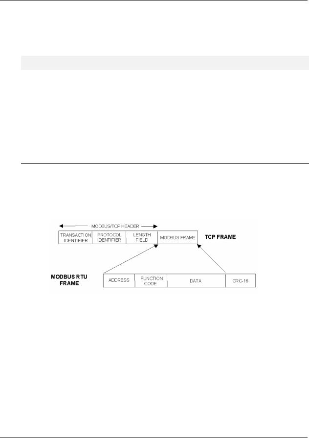
It is simply an encapsulation of Modicon’s Modbus RTU protocol within a TCP/IP frame as shown below, which includes header information and the Modbus frame.
Figure 1-1 Modbus RTU Protocol within a TCP/IP Frame
The Open Modbus/TCP Specification is followed with respect to the physical, data link, and network layers. The message structure within the Modbus frame uses standard Modbus RTU function codes.
The Address part of the Modbus frame is not used (set to 00) since there is no sub-addressing intended or required. The controller IP address is the identifying address, set independently at the controller.
The error checking is supported by TCP/IP network protocols and not part of the Modbus frame.
The Transaction Identifiers and Protocol Identifiers in the header are normally all 0’s (4 bytes total) while the Length field identifies the number of bytes in the Modbus frame. The controller will transmit the correct number of bytes for the remainder of the frame. However, the controller does not check this field for messages received.
The standard IEEE 32-bit floating point and 16-bit integer formats are used.
2 |
HC900 Hybrid Controller Communications User Guide |
Revision 10 |
|
|
12/07 |
Introduction
Modbus/TCP Interface
Parameter Addressing
The definition in Table 6-1 is the fixed map overview listing starting and ending addresses.
Greater detail for parameter addressing relating to a particular function class (e.g, loops, setpoint programmer, signal tags) is in referenced sub-sections. Function Codes 1, 2, 3, 4, 5, 6, 8, 16 (10h), and 17 (11h) are supported (see Table 4-1 Modbus/TCP and Modbus RTU Function Codes Definitions).
Examples for read or write access to parameters supported by the various function codes are provided in Sections 4.3 through 4.11.
Reference
The Open Modbus/TCP Specification can be obtained at the Modicon website:
http://www.modicon.com/openmbus/standards/openmbus.htm
HC900 Ethernet Communications Setup
See the HC900 Hybrid Control (HC) Designer Users Guide, Doc. # 51-52-25-110 or respective HC Designer Help Files for setting up the following network parameters:
IP Address, Subnet Mask (optional), Default Gateway IP Address (optional)
1.Be sure the PC, HMI panel, or other Host device has a Network Interface Card (NIC) with an IP address (fixed or DHCP served) that allows access to controllers on the same or other subnet. Consult your IT department or network administrator for allocating IP addresses to the controllers as required.
2.You will need to set each controller’s IP address prior to network connection since every HC900 controller is shipped with the default IP address of 192.168.1.254. Placing multiple controllers on the same network before they have been given unique IP addresses will cause problems.
3.On the PC, use the Utilities Worksheet in the HC Designer software to set up the serial RS-232 connection to the controller at the desired baud rate. This will require a null modem cable.
4.Select the Set Controller’s Network Parameters button. Using the wizard (bottom radio button), select the PC COM port to be used, then set the controller’s new network parameters including IP address, Subnet Mask (if other than default, 255.255.255.0), and Default Gateway IP address (if required, otherwise leave at default 0.0.0.0). See your IT network administrator for proper entries. (Refer to the on-line help provided with the HC Designer software, Utilities Worksheet, Set Controller’s Network Parameters, for further details on this step).
Note: This setup will require the controller to be placed temporarily in the Program mode. After the new network parameters have been downloaded, the controller will conduct a Cold Start in its transition to RUN. This will cause an initialization if there is a current configuration in the controller.
The fixed IP address of each controller shall be set independently prior to placing on the network. See your IT systems administrator for allocating IP addresses, subnet masks, or default gateway IP address as necessary (network address filtering and routing may be necessary if the controller network access will not to be confined locally within the plant environment).
Revision 10 |
HC900 Hybrid Controller Communications User Guide |
3 |
12/07 |
|
|

Introduction
Modbus/TCP Interface
Ethernet 10/100Base-T Network Connections
Ethernet 10/100Base-T networks operating at 10/100MB/sec. are supported. A typical network arrangement is as shown below.
PC HMI
To other subnets
 Switch
10/100Base-T
10/100Base-T
RS232/RS485
Serial Ports S1 & S2
Ethernet Host Port E1
Ethernet Host Port E2
I/O Port
C70
Run/Pgm
Pgm Run
Run/Pgm |
S1 |
S2 |
E1
E2
I/O
C70 |
S1 |
S2 |
E1 |
E2 |
I/O |
IP Address 193.142.165.45
C70 |
S1 |
S2 |
E1 |
E2 |
I/O |
IP Address 193.142.165.46
Figure 1-2 Ethernet 10/100Base-T Network Connections
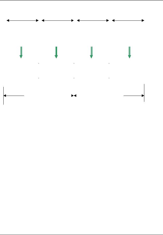
Setting Up the Modbus/TCP Double Register Format
The HC900 predominantly uses an IEEE floating point format for communicating data to software applications providing Modbus/TCP protocol communications drivers. A floating point value is sent as (2) consecutive 16-bit registers, each register of which consists of two 8-bit bytes. Some software packages require the registers and bytes to be sent in a certain order. The controller can be configured to deliver the data in four different byte orders.
The Hybrid Control Designer software tool allows this order to be selected as follows:
1.Using the Utilities Worksheet in the HC Designer software, access the Set Controller Network Parameters button and make the selection to change the Modbus TCP Double Register Format (middle radio button).
2.With the Port selected for downloading this order (using a COM port or Network port), select the appropriate byte order format if the default (FP B) is not appropriate for the application. See Table 3-1, page 10.
3.Select Next and verify (by the response in the dialog box) that the change has been made in the controller. This order can be changed in the RUN mode.
The Modbus TCP double register transmission format selection, FP LB “Little Endian Byte-Swapped”, would be selected for interface to most third party software packages which use this format as standard. The default, FP B “Big Endian” is used with SpecView32 or Honeywell’s PlantScape/Experion/EBI software and follows the “Honeywell” default format of other control and recording products. It should be noted that most PC software packages offer a register (word) swap selection in their driver package anyway, so there should never be an incompatibility.
4 |
HC900 Hybrid Controller Communications User Guide |
Revision 10 |
|
|
12/07 |

Introduction
Modbus RTU RS232/RS485 Communication Ports
1.3 Modbus RTU RS232/RS485 Communication Ports
This implementation is designed to provide a popular data exchange format connecting the HC900 to both Honeywell and foreign master devices via the RS232 and RS485 communication ports. The Modbus RTU allows the instrument to be a citizen on a data link shared with other devices, which subscribe to the Modicon Modbus Protocol Reference Guide PI-MBUS-300 Rev. G specification.
These instruments DO NOT emulate any MODICON type device. The Modbus RTU specification is respected in the physical and data link layers. The message structure of the Modbus RTU function codes is employed and standard IEEE 32-bit floating point and integer formats are used. Data register mapping is unique to the HC900 and other Honeywell instruments. Section 6 describes the parameter mapping for the HC900.
Modbus RTU Message Format
|
Table 1-1 Modbus RTU Message Formats |
Coding system |
8 bit binary |
|
|
Number of data bits per |
10, 11, or 12 Bits |
character |
start bits - 1 |
|
|
|
data bits - 8 |
|
parity bits – 0 or 1 selectable |
|
stop bits – 1 or 2 selectable |
|
|
Parity |
None, odd, even selectable |
|
|
Bit transfer rate |
1200, 2400, 4800, 9600, 19200, 38400, 57600 Selectable |
|
|
Duplex |
Half duplex Transceiver or TX/RX |
|
|
Error checking |
CRC (cyclic redundancy check) |
|
|
Polynomial |
(CRC-16 10100000000001) |
|
|
Bit transfer order |
LSB first |
|
|
End of message |
Idle line for 3.5 or more characters (>1.82 msec for 19200). |
|
|
Modbus RTU Link Layer
The link layer includes the following properties/behaviors:
•Slave address recognition,
•Start / End of Frame detection,
•CRC-16 generation / checking,
•Transmit / receive message time-out,
•Buffer overflow detection,
•Framing error detection,
•Idle line detection.
Errors detected by the physical layer in messages received by the slave are ignored and the physical layer automatically restarts by initiating a new receive on the next idle line detection.
Revision 10 |
HC900 Hybrid Controller Communications User Guide |
5 |
12/07 |
|
|

Introduction
Modbus RTU RS232/RS485 Communication Ports
General Modbus RTU message format
Query message format
[Slave Address, Function Code, Function code dependent data, CRC 16]
Response message format
[Slave Address, Function Code*, Function code dependent data, CRC 16]
* If an error is detected in a valid message the response function code is modified by adding 80 (hex) and the function code dependent data is replaced by an exception response code as described in 5. Modbus RTU Exception Codes .
Between messages, the RS-485 link is in a high impedance state. During this time receiving devices are more susceptible to noise generated false start of messages. Although noise-generated messages are rejected due to address, framing, and CRC checking, they can cause the loss of a good message when they are included in the message stream. In the slave the transmitting device enables its transmitter line diver and forces an idle line state onto the link for three character time slots prior to transmitting. This forces termination of any noise generated messages and improves message frame synchronization.
Modbus RTU Data Layer
The data layer includes:
•Diagnostic loopback,
•Function code recognition / rejection,
•Busy / repoll,
•Data error code generation
Errors detected by the data layer are rejected and the slave responds to the polling device with a Modbustype status exception error. A summary of the Modbus status exception codes is listed in Section 5. Modbus RTU Exception Codes.
6 |
HC900 Hybrid Controller Communications User Guide |
Revision 10 |
|
|
12/07 |
IEEE 32-bit Floating Point Register Information
IEEE Floating Point Data Format
2. IEEE 32-bit Floating Point Register Information
The Modbus interface supports IEEE 32-bit floating point information for several of the function codes.
2.1 IEEE Floating Point Data Format
The formula for calculating the floating point number is:
mantissa x 2 (exponent -127)
(23 bit signed binary with 8 bit biased binary exponent)
|
byte 4 |
|
byte 3 |
|
byte 2 |
|
byte 1 |
3 |
2 |
2 |
1 |
1 |
|
|
|
1 |
4 |
3 |
6 |
5 |
8 |
7 |
0 |
xxxxxxxx |
x.xxxxxxx |
xxxxxxxx |
xxxxxxx |
||||
mantissa (23 bits)
implied binary point for mantissa
exponent (8 bit unsigned value)
sign of the mantissa 0 = positive, 1 = negative
Figure 2-1 IEEE Floating Point Data format
Mantissa and Sign
The mantissa is defined by a sign bit (31) and a 23-bit binary fraction. This binary fraction is combined with an “implied” value of 1 to create a mantissa value, which is greater than or equal to 1.0 and less than 2.0.
The mantissa is positive if the sign bit is zero (reset), and negative if the sign bit is one (set). For example:
DECIMAL |
HEXADECIMAL |
BINARY |
100 |
42C80000 |
01000010 11001000 00000000 00000000 |
The sign bit (31) is zero, indicating a positive mantissa. Removing the sign bits and exponent bits, the mantissa becomes:
HEXADECIMAL BINARY
480000 |
xxxxxxxx x1001000 00000000 00000000 |
Add an “implied” value of one to the left of the binary point:
BINARY
1.1001000 00000000 00000000
Using positioned notation, this binary number is equal to:
10. +(1x2-1 ) +(0x2-2 ) +(0x2-3 ) +(1x2-4 ) =10. +05. +0.0 +0.0 +0.0625 =15625.
Revision 10 |
HC900 Hybrid Controller Communications User Guide |
7 |
12/07 |
|
|

Exponent
The exponent is defined by an unsigned 8-bit binary value (bits 23 through 30). The value of the exponent is derived by performing a signed subtraction of 127 (decimal) from the 8-bit exponent value.
DECIMAL |
HEXADECIMAL |
BINARY |
100 |
42C80000 |
01000010 11001000 00000000 00000000 |
Removing the sign and mantissa bits, the exponent becomes:
DECIMAL |
HEXADECIMAL |
BINARY |
133 |
85 |
x1000010 1xxxxxxx xxxxxxxx xxxxxxxx |
or: |
|
|
1x27 +0x26 |
+0x25 +0x24 |
+0x23 +1x22 +0x21 +1x20 |
Subtract a bias of 127 (decimal) from the exponent to determine its value: 133 – 127 = 6.
Mantissa and Exponent Combination
Combining the mantissa and exponent from the two previous examples:
float number = mantissa x 2exponent
float number = 1.5625 x 26 =15625. x 64 = 100.0
Below is a list of sample float values in IEEE format:
DECIMAL |
HEXADECIMAL |
|
|
100.0 |
42C80000 |
|
|
-100.0 |
C2C80000 |
|
|
0.5 |
3F000000 |
|
|
-1.75 |
BFE00000 |
|
|
0.0625 |
3D800000 |
|
|
1 |
3F800000 |
|
|
0 |
00000000 |
|
|
8 |
HC900 Hybrid Controller Communications User Guide |
Revision 10 |
|
|
12/07 |

IEEE 32-bit Floating Point Register Information
IEEE Floating Point Data Format
Reserved Operands
Per the Standard certain exceptional forms of floating point operands are excluded from the numbering system. These are as follows:
EXCEPTION |
EXPONENT |
MANTISSA |
+/- Infinity |
All 1’s |
All 0’s |
|
|
|
Not-a-Number (NAN) |
All 1’s |
Other than 0’s |
|
|
|
Denormalized Number |
All 0’s |
Other than 0’s |
|
|
|
Zero |
All 0’s |
All 0’s |
|
|
|
Revision 10 |
HC900 Hybrid Controller Communications User Guide |
9 |
12/07 |
|
|

3. Modbus Double Register Format
Data that is 32 bits requires 2 sequential registers (4 bytes) to transfer its data. Data of this type includes IEEE 32bit floating point, 32-bit signed integer and 32-bit unsigned integer. The stuffing order of the bytes into the two registers differs among Modbus/TCP hosts. To provide compatibility, the double register format for the HC900 controller is configurable.
To set the controller’s double register byte order, go to the “Set Controller Network Parameters ” wizard in the "Controller Utilities Function" section of the Utilities Tab on the Hybrid Control Designer and configure “Modbus Double Register Format”. This can be done in the RUN mode.
The selections are:
Table 3-1 Modbus Double Register Format Selections
Selection |
Description |
Byte order |
Notes |
|
|
(See Figure |
|
|
|
2-1) |
|
FP B |
Floating Point Big Endian Format |
4, 3, 2, 1 |
HC900 default |
|
|
|
|
FP BB |
Floating Point Big Endian with |
3, 4, 1, 2 |
|
|
byte-swapped |
|
|
|
|
|
|
FP L |
Floating Point Little Endian Format |
1, 2, 3, 4 |
|
|
|
|
|
FP LB |
Floating Point Little Endian with |
2, 1, 4, 3 |
Modicon and |
|
byte-swapped |
|
Wonderware |
|
|
|
standard |
|
|
|
|
See IEEE Formats on page IEEE Floating Point Formats on page 11 and 32-bit integer formats on page 13.
NOTE: Byte Swapping only applies to Function Codes 3, 4, and 16.
10 |
HC900 Hybrid Controller Communications User Guide |
Revision 10 |
|
|
12/07 |

Modbus Double Register Format
IEEE Floating Point Formats
3.1 IEEE Floating Point Formats
FP B - Floating Point Big Endian Format: |
|
|
||
Bit 31 |
|
|
|
Bit 0 |
|
|
|
|
|
|
E0 M22 M21M20 M19 M18 M17 M16 |
M7 M6 M5 M4 M3 M2 M1 M0 |
||
S E7 E6 E5 E4 E3 E2 E1 |
M15 M14 M13 M12 M11 M10 M9 M8 |
|
||
|
High |
Low |
High |
Low |
|
REGISTER N |
REGISTER N+1 |
|
|
|
(High) |
|
(Low) |
|
S=Sign |
E=Exponent |
M=Mantissa |
|
|
FP BB - Floating Point Big Endian with Byte Swapped Format:
|
|
Bit 31 |
|
|
|
Bit 24 |
Bit 15 |
|
Bit 8 |
||||||||
|
|
|
|
||||||||||||||
|
|
|
|
|
|
||||||||||||
|
|
|
|
|
|
|
|
|
|
|
|
|
|
|
|
|
|
|
|
|
S E7 E6 E5 E4 E3 E2 E1 |
M15 M14 M13 M12 M11 M10 M9 M8 |
|||||||||||||
|
|
|
|
|
|
|
|
|
|
|
|||||||
Bit 23 |
|
Bit 16 |
Bit 7 |
|
|
|
Bit 0 |
|
|
||||||||
|
|
|
|
|
|
||||||||||||
|
|
|
|
|
|
|
|
|
|
|
|
|
|
|
|
|
|
E0 M22 M21M20 M19 M18 M17 M16 |
M7 M6 M5 M4 M3 M2 M1 M0 |
|
|
||||||||||||||
High |
|
Low |
|
High |
|
Low |
|
|
|
|
|
|
|
REGISTER N |
REGISTER N+1 |
|
||||
(High) |
|
|
(Low) |
|
||
S=Sign E=Exponent |
M=Mantissa |
|
|
|
||
continued next page
Revision 10 |
HC900 Hybrid Controller Communications User Guide |
11 |
12/07 |
|
|
FP L - Floating Point Little Endian Format: |
|
|
||
|
Bit 15 |
Bit 8 |
Bit 31 |
Bit 24 |
|
M15 M14 M13 M12 M11 M10 M9 M8 |
S E7 E6 E5 E4 E3 E2 E1 |
||
Bit 7 |
Bit 0 |
Bit 23 |
Bit 16 |
|
M7 M6 M5 M4 M3 M2 M1 M0 |
E0 M22 M21M20 M19 M18 M17 M16 |
|
||
|
High |
Low |
High |
Low |
|
REGISTER N |
|
REGISTER N+1 |
|
|
(High) |
|
(Low) |
|
S=Sign |
E=Exponent M=Mantissa |
|
|
|
FP LB - Floating Point Little Endian with Byte Swapped Format:
|
|
Bit 7 |
|
|
Bit 0 |
Bit 23 |
|
Bit 16 |
||||||||
|
|
|
|
|
||||||||||||
|
|
|
|
|
|
|
|
|
|
|
|
|
|
|
|
|
|
|
M7 M6 M5 M4 M3 M2 M1 M0 |
|
E0 M22 M21M20 M19 M18 M17 M16 |
||||||||||||
Bit 15 |
|
|
Bit 8 |
Bit 31 |
|
Bit 24 |
|
|
||||||||
|
|
|
|
|
||||||||||||
|
|
|
|
|
|
|
|
|
|
|
|
|
||||
M15 M14 M13 M12 M11 M10 M9 M8 |
S E7 E6 E5 E4 E3 E2 E1 |
|
|
|||||||||||||
High |
|
Low |
High |
|
Low |
|
|
|
|
|
|
REGISTER N |
|
REGISTER N+1 |
|
||
(High) |
|
(Low) |
|
||
S=Sign E=Exponent M=Mantissa
Figure 3-1 IEEE Floating Point Formats
Table 3-2 IEEE Floating Point Number Examples in FP B Format
|
|
Value |
|
|
IEEE FP B |
|
Register N |
Register N+1 |
|
||
|
|
(decimal) |
|
|
MSB LSB |
|
high |
low |
high |
low |
|
|
|
|
|
|
|
|
|
|
|
|
|
|
100.0 |
|
|
42C80000h |
42h |
C8h |
00h |
00h |
|
||
|
|
|
|
|
|
|
|
|
|
||
|
55.32 |
|
|
425D47AEh |
42h |
5Dh |
47h |
AEh |
|
||
|
|
|
|
|
|
|
|
|
|
||
|
2.0 |
|
|
40000000h |
40h |
00h |
00h |
00h |
|
||
|
|
|
|
|
|
|
|
|
|
||
|
1.0 |
|
|
3F800000h |
3Fh |
80h |
00h |
00h |
|
||
|
|
|
|
|
|
|
|
|
|
||
|
-1.0 |
|
|
BF800000h |
BFh |
80h |
00h |
00h |
|
||
|
|
|
|
|
|
|
|
|
|
|
|
|
|
|
|
|
|
|
|
|
|
|
|
12 |
|
|
|
|
HC900 Hybrid Controller Communications User Guide |
|
Revision 10 |
||||
|
|
|
|
|
|
|
|
|
|
12/07 |
|
Modbus Double Register Format
Unsigned/signed 32-bit Register Formats
3.2 Unsigned/signed 32-bit Register Formats
The formats descriptions below use the value 12345678 Hex as an example. Where the binary representation is:
|
Byte 4 = 12 Hex |
|
|
|
Byte 3 = 34 Hex |
|
|
|
Byte 2 = 56 Hex |
|
|
|
Byte 1 = 78 Hex |
|
|
|||||||||||||||||||
|
|
|
|
|
|
|
|
|
|
|
|
|
|
|
|
|
|
|
|
|
|
|
|
|
|
|
|
|
|
|
|
|
|
|
Bits |
31 |
30 |
29 |
28 |
27 |
26 |
25 |
24 |
23 |
22 |
21 |
20 |
19 |
|
18 |
17 |
16 |
15 |
14 |
13 |
12 |
11 |
|
10 |
9 |
8 |
7 |
6 |
5 |
4 |
3 |
2 |
1 |
0 |
|
|
|
|
|
|
|
|
|
|
|
|
|
|
|
|
|
|
|
|
|
|
|
|
|
|
|
|
|
|
|
|
|
|
|
|
0 |
0 |
0 |
1 |
0 |
0 |
1 |
0 |
0 |
0 |
1 |
1 |
0 |
|
1 |
0 |
0 |
0 |
1 |
0 |
1 |
0 |
|
1 |
1 |
0 |
0 |
1 |
1 |
1 |
1 |
0 |
0 |
0 |
|
|
|
|
|
|
|
|
|
|
|
|
|
|
|
|
|
|
|
|
|
|
|
|
|
|
|
|
|
|
|
|
|
|
|
FP B – Big Endian Format
The value 12345678 Hex will be represented as follows:
Bit 31 |
|
|
|
|
Bit 0 |
|
|
|
|
||
|
|
|
|
|
|
|
Byte 4 |
Byte 3 |
Byte 2 |
Byte 1 |
|
|
12 Hex |
34 Hex |
56 Hex |
78 Hex |
|
High |
Low |
High |
Low |
|
|
|
|
REGISTER N |
|
|
|
|
REGISTER N+1 |
|
|
|
|||
(High) |
|
|
(Low) |
||
|
|
|
|
|
|
Revision 10 |
HC900 Hybrid Controller Communications User Guide |
13 |
12/07 |
|
|
FP BB – Big Endian Byte Swapped Format
The value 12345678 Hex will be represented as follows:
Bit 23 Bit 16 Bit 31 Bit 24 Bit 7 Bit 0 Bit 15 Bit 8
Byte 3 |
Byte 4 |
Byte 1 |
Byte 2 |
34 Hex |
12 Hex |
78 Hex |
56 Hex |
High |
Low |
High |
Low |
|
|
|
|
REGISTER N |
|
|
|
|
REGISTER N+1 |
|
|
|
|||
(High) |
|
|
(Low) |
||
|
|
|
|
|
|
14 |
HC900 Hybrid Controller Communications User Guide |
Revision 10 |
|
|
12/07 |

Modbus Double Register Format
Unsigned/signed 32-bit Register Formats
FP L – Little Endian Format
The value 12345678 Hex will be represented as follows:
Bit 7 |
Bit 0 Bit 15 |
Bit 8 Bit 23 |
Bit 16 |
Bit 31 |
Bit 24 |
Byte 1 |
Byte 2 |
Byte 3 |
|
|
Byte 4 |
78 Hex |
56 Hex |
34 Hex |
|
|
12 Hex |
High |
Low |
High |
Low |
|
|
|
|
REGISTER N |
|
|
|
|
REGISTER N+1 |
|
|
|
|||
(High) |
|
|
(Low) |
||
|
|
|
|
|
|
Revision 10 |
HC900 Hybrid Controller Communications User Guide |
15 |
12/07 |
|
|
FP LB – Little Endian Byte Swap Format
The value 12345678 Hex will be represented as follows:
Bit 15 |
Bit 8 Bit 7 |
Bit 0 Bit 31 |
Bit 24 |
Bit 23 |
Bit 16 |
Byte 2 |
Byte 1 |
Byte 4 |
|
|
Byte 3 |
56 Hex |
78 Hex |
12 Hex |
|
|
34 Hex |
High |
Low |
High |
Low |
|
|
|
|
REGISTER N |
|
|
|
|
REGISTER N+1 |
|
|
|
|||
(High) |
|
|
(Low) |
||
|
|
|
|
|
|
16 |
HC900 Hybrid Controller Communications User Guide |
Revision 10 |
|
|
12/07 |

Modbus/TCP & Modbus RTU Function Codes
Function code definitions
4.Modbus/TCP & Modbus RTU Function Codes
4.1Function code definitions
The HC900 Modbus protocol uses a subset of the standard Modbus function codes to provide access to processrelated information. These standard function codes provide basic support for IEEE 32-bit floating point numbers, 32-bit unsigned/signed integer and 16-bit integer register representation of instrument’s process data.
Repolling of data is not supported by this instrument.
Table 4-1 Modbus/TCP and Modbus RTU Function Codes Definitions
Function Code |
Name |
Usage |
01 |
Read Coil Status |
Read the state of a digital output |
|
|
|
02 |
Read Input Status |
Read the state of a digital input |
|
|
|
03 |
Read Holding Registers |
Read data in 16-bit Register Format (high/low). Used to read |
|
|
integer or floating point process data. Registers are |
|
|
consecutive and are imaged from the instrument to the host. |
|
|
|
04 |
Read Input Registers |
Provides Read access to any Analog Input Channel |
|
|
positioned in any Rack or Slot. |
|
|
|
05 |
Force Single Coil |
Write data to force a digital output ON/OFF |
|
|
Values of FF 00 forces digital output ON |
|
|
Values of 00 00 forces digital output OFF |
|
|
Values of FF FF releases the force of the digital output |
|
|
All other values are illegal and will not effect the digital output. |
|
|
|
06 |
Preset Single Register |
Write Data in 16-bit Integer Format (high/low) ONLY. |
|
|
|
08 |
Loopback Test |
Used for diagnostic testing of the communications port. |
|
|
|
16 (10h) |
Preset Multiple Registers |
Write Data in 16-bit Format (high/low). Used to write integer |
|
|
and floating point override data. Registers are consecutive |
|
|
and are imaged from the host to the instrument. |
|
|
|
17 (11h) |
Report Device ID |
Read instrument ID and connection information, ROM version, |
|
|
etc. |
|
|
|
Revision 10 |
HC900 Hybrid Controller Communications User Guide |
17 |
12/07 |
|
|

4.2 Fixed Modbus Map
Table 4-2 and Table 4-3 list the the maximum number of Object Addresses and maximum number of registers allowed per request. Also shown are differences between firmware versions 2.3 and 2.4.
Note 1: In versions 4.0 and higher these maximums apply to fixed map but not to the custom map. Note 2: In versions 4.0 and higher function code 03 is not available for analog inputs.
Table 4-2 Maximum Number of Objects (fixed map only)
Note: objects marked with * have multiple parameters and therefore occupy multiple registers. For example, a PID loop has over 40 parameters that can be accessed.
Object Name |
|
Max. No. of Objects |
Function Code |
||||
|
C30 |
|
|
C50/C70/C70R |
|
||
|
|
|
|
|
|
||
Analog Inputs |
|
96/12 slots v2.3 |
|
640 v2.3 |
3: can only access first 8 |
||
|
|
192/12 slots v2.4 |
|
1280 v2.4 |
slots of rack 1. Not available |
||
|
|
|
|
|
|
|
in version 4.0 or higher. |
|
|
|
|
|
|
|
4: can access all slots and |
|
|
|
|
|
|
|
racks |
Discrete Input |
192/12 slots v2.3 |
|
1280 v2.3 |
2 |
|||
|
|
384/12 slots v2.4 |
|
2560 v2.4 |
|
||
Discrete Output/Coil |
192/12 slots v2.3 |
|
1280 v2.3 |
1: read |
|||
|
|
384/12 slots v2.4 |
|
2560 v2.4 |
5: force |
||
Loop* |
8 |
|
32 |
|
3 |
||
Variable Value |
600 |
|
600 |
|
3 |
||
Set Point Programmer Value* |
8 |
|
8 |
|
3 |
||
Segments per Set Point |
50 |
|
50 |
|
3 |
||
Programmer* |
|
|
|
|
|
|
|
Signal tags |
2000 |
|
|
2000 (C50) |
3 |
||
|
|
|
|
|
5000 (C70/C70R) |
|
|
Scheduler Value* |
2 |
|
2 |
|
3 |
||
Segments per Schedule* |
50 |
|
50 |
|
3 |
||
Sequencer* |
4 |
|
4 |
|
3 |
||
Stage* |
8 |
|
8 |
|
3 |
||
|
|
|
|
|
|
||
Ramp* |
8 |
|
8 |
|
3 |
||
Hand-Off-Auto* |
16 |
|
16 |
|
3 |
||
Alternator* |
6 |
|
6 |
|
3 |
||
Device Control* |
16 |
|
16 |
|
3 |
||
User Defined Registers |
1024 |
|
1024 |
|
3 |
||
18 |
HC900 Hybrid Controller Communications User Guide |
Revision 10 |
|
|
12/07 |

Modbus/TCP & Modbus RTU Function Codes
Fixed Modbus Map
Table 4-3 Maximum Number of Registers Allowable per Request
Function |
|
Max. No. of |
Code |
|
Registers |
1, 2 |
2040 bits |
|
|
|
|
3, 4 |
127 Registers |
|
|
63 Floats |
|
|
|
|
5 |
1 |
Coil |
|
|
|
6 |
1 |
Register |
|
|
|
10h |
127 Registers |
|
|
63 Floats |
|
|
|
|
Revision 10 |
HC900 Hybrid Controller Communications User Guide |
19 |
12/07 |
|
|

4.3 Function Code 01 – Read Digital Output Status
Description
Function code 01 (0X references) is used to read a digital output’s ON/OFF status of the HC900 using 16 bit addressing for DO access and data is returned in a binary format mapped into bytes.
The Modbus Comm Digital I/O Channel-to-address mapping is shown starting on page 26. Broadcast is not supported.
Query
The query message specifies the starting Digital Output (DO) and the quantity of DOs to read. The DO address in the message is based on the rack slot and channel number of the digital output being read.
Example Query: Read DO channels 1 to 16, located in Rack #1, Slot #1; from the controller with slave address 1.
Query message format for function code 01
|
Slave |
Function |
Starting |
Starting |
|
Number |
Number |
CRC |
CRC |
|
Address |
Code |
Address |
Address |
|
DO |
DO |
(RTU) |
(RTU) |
|
(00 for TCP) |
|
High |
Low |
|
High |
Low |
|
|
TCP Example |
00 |
01 |
00 |
00 |
00 |
10 |
|
|
|
|
|
|
|
|
|
|
|
|
|
RTU Example |
01 |
01 |
00 |
00 |
00 |
10 |
CRC |
CRC |
|
|
|
|
|
|
|
|
|
|
|
Response
The DO status in the response message is packed as one DO per bit of the data field. Status is indicated as: 1 = ON; 0 = OFF. The LSB of the first data byte contains the DO addressed in the query. The other DOs follow toward the high order end of this byte, and from low order to high order in subsequent bytes.
If the returned DO quantity is not a multiple of eight, the remaining bits in the final data byte will be padded with zeros (toward the high order end of the byte). The byte count field specifies the quantity of data bytes returned.
Example Response: DO channels 2 and 6 located in Rack #1, Slot #1 are on; all others are off.
Response message format for function code 01
|
Slave |
Function |
Byte |
Data |
Data |
CRC |
CRC |
|
Address |
Code |
Count |
|
|
(RTU) |
(RTU) |
|
(00 for TCP) |
|
|
|
|
|
|
|
|
|
|
|
|
|
|
TCP Example |
00 |
01 |
02 |
22 |
00 |
|
|
|
|
|
|
|
|
|
|
RTU Example |
01 |
01 |
02 |
22 |
00 |
CRC |
CRC |
|
|
|
|
|
|
|
|
In the response the status of DOs 1 - 8 is shown as the byte value 22 hex, or 0010 0010 binary. DO 8 is the MSB of this byte, and DO 1 is the LSB. Left to right, the status of DO 8 through 1 is: OFF-OFF-ON-OFF- OFF-OFF-ON-OFF. The status of DOs 9 - 16 are shown a 00hex, or 0000 0000 with the same bit ordering.
20 |
HC900 Hybrid Controller Communications User Guide |
Revision 10 |
|
|
12/07 |

Modbus/TCP & Modbus RTU Function Codes
Function Code 01 – Read Digital Output Status
Digital I/O Channel to Address Mapping
If you have any 32-channel DI/DO modules or if you have firmware version 2.4 or higher you must use the newer maps in Table 4-4 and Table 4-5. However, use the older maps in Table 4-6 and Table 4-7 if:
•Your controller is firmware version 2.3 or earlier or
•You have already mapped out 16-channel DI/DO, have no 32-channel DI/DO modules, and don’t want to change to the newer map.
Note: Up to 16 slots are accommodated in the protocol even though the largest rack available supports 12 slots.
Each DI/DO consumes 1 Modbus bit address.
Decimal addressing is typically non-zero based for DI/DO access (1-based), applicable to coil or register address.
Table 4-4 DI/DO Address Map (v2.4 and higher, up to 32-channel)
Rack |
Channels |
|
Coil number/register number |
Modbus Hex |
||
|
|
|
|
|
Address Range |
|
1* |
1 - 512 |
2001 |
– 2512 |
7D0 |
– 9CF |
|
|
|
|
|
|
|
|
2 |
513 – 1024 |
2513 |
– 3024 |
9D0 |
– BCF |
|
|
|
|
|
|
|
|
3 |
1025 |
– 1536 |
3025 |
– 3536 |
BD0 – DCF |
|
|
|
|
|
|
|
|
4 |
1537 |
- 2048 |
3537 |
– 4048 |
DD0 – FCF |
|
|
|
|
|
|
|
|
5 |
2049 |
- 2560 |
4049 |
- 4560 |
FD0 – 11CF |
|
|
|
|
|
|
|
|
*See Table 4-5 for detailed map of Rack |
#1 |
|
|
|||
|
|
|
|
|
|
|
The coil (register) number for a DI/DO is based on the DI/DO’s position in the card cage. It is determined from the formula:
Coil (register) Number = [(Rack-1)*512] + [(Slot-1)*32] + channel in module + 2000
Example: To monitor a coil (register) located in the 2nd channel of slot 10 of rack 3, the Modbus coil (register) number is:
[(3-1)*512] + [(10-1)*32] + 2 + 2000 = 3314
Some third party software packages will require the 1-based coil/register number to be used for the address while others will require the 0-based hex address.
Revision 10 |
HC900 Hybrid Controller Communications User Guide |
21 |
12/07 |
|
|

Table 4-5 Rack #1 DI/DO Address map (version 2.4 and higher, up to 32-channel)
|
Slot 1 |
|
|
|
Slot 2 |
|
|
|
Slot 3 |
|
|
|
Slot 4 |
|
CH# |
Coil/ |
Addr. |
|
CH# |
Coil/ |
Addr. |
|
CH# |
Coil/ |
Addr. |
|
CH# |
Coil/ |
Addr. |
|
register |
Hex |
|
|
register |
Hex |
|
|
register |
Hex |
|
|
register |
Hex |
|
|
|
|
|
|
|
|
|
|
|
|
|
|
|
32 |
2032 |
7EF |
|
32 |
2064 |
80F |
|
32 |
2096 |
82F |
|
32 |
2128 |
84F |
|
|
|
|
|
|
|
|
|
|
|
|
|
|
|
31 |
2031 |
7EE |
|
31 |
2063 |
80E |
|
31 |
2095 |
82E |
|
31 |
2127 |
84E |
30 |
2030 |
7ED |
|
30 |
2062 |
80D |
|
30 |
2094 |
82D |
|
30 |
2126 |
84D |
29 |
2029 |
7EC |
|
29 |
2061 |
80C |
|
29 |
2093 |
82C |
|
29 |
2125 |
84C |
28 |
2028 |
7EB |
|
28 |
2060 |
80B |
|
28 |
2092 |
82B |
|
28 |
2124 |
84B |
27 |
2027 |
7EA |
|
27 |
2059 |
80A |
|
27 |
2091 |
82A |
|
27 |
2123 |
84A |
|
|
|
|
|
|
|
|
|
|
|
|
|
|
|
26 |
2026 |
7E9 |
|
26 |
2058 |
809 |
|
26 |
2090 |
829 |
|
26 |
2122 |
849 |
25 |
2025 |
7E8 |
|
25 |
2057 |
808 |
|
25 |
2089 |
828 |
|
25 |
2121 |
848 |
|
|
|
|
|
|
|
|
|
|
|
|
|
|
|
24 |
2024 |
7E7 |
|
24 |
2056 |
807 |
|
24 |
2088 |
827 |
|
24 |
2120 |
847 |
23 |
2023 |
7E6 |
|
23 |
2055 |
806 |
|
23 |
2087 |
826 |
|
23 |
2119 |
846 |
|
|
|
|
|
|
|
|
|
|
|
|
|
|
|
22 |
2022 |
7E5 |
|
22 |
2054 |
805 |
|
22 |
2086 |
825 |
|
22 |
2118 |
845 |
21 |
2021 |
7E4 |
|
21 |
2053 |
804 |
|
21 |
2085 |
824 |
|
21 |
2117 |
844 |
20 |
2020 |
7E3 |
|
20 |
2052 |
803 |
|
20 |
2084 |
823 |
|
20 |
2116 |
843 |
|
|
|
|
|
|
|
|
|
|
|
|
|
|
|
19 |
2019 |
7E2 |
|
19 |
2051 |
802 |
|
19 |
2083 |
822 |
|
19 |
2115 |
842 |
18 |
2018 |
7E1 |
|
18 |
2050 |
801 |
|
18 |
2082 |
821 |
|
18 |
2114 |
841 |
|
|
|
|
|
|
|
|
|
|
|
|
|
|
|
17 |
2017 |
7E0 |
|
17 |
2049 |
800 |
|
17 |
2081 |
820 |
|
17 |
2113 |
840 |
16 |
2016 |
7DF |
|
16 |
2048 |
7FF |
|
16 |
2080 |
81F |
|
16 |
2112 |
83F |
|
|
|
|
|
|
|
|
|
|
|
|
|
|
|
15 |
2015 |
7DE |
|
15 |
2047 |
7FE |
|
15 |
2079 |
81E |
|
15 |
2111 |
83E |
14 |
2014 |
7DD |
|
14 |
2046 |
7FD |
|
14 |
2078 |
81D |
|
14 |
2110 |
83D |
|
|
|
|
|
|
|
|
|
|
|
|
|
|
|
13 |
2013 |
7DC |
|
13 |
2045 |
7FC |
|
13 |
2077 |
81C |
|
13 |
2109 |
83C |
12 |
2012 |
7DB |
|
12 |
2044 |
7FB |
|
12 |
2076 |
81B |
|
12 |
2108 |
83B |
11 |
2011 |
7DA |
|
11 |
2043 |
7FA |
|
11 |
2075 |
81A |
|
11 |
2107 |
83A |
|
|
|
|
|
|
|
|
|
|
|
|
|
|
|
10 |
2010 |
7D9 |
|
10 |
2042 |
7F9 |
|
10 |
2074 |
819 |
|
10 |
2106 |
839 |
9 |
2009 |
7D8 |
|
9 |
2041 |
7F8 |
|
9 |
2073 |
818 |
|
9 |
2105 |
838 |
|
|
|
|
|
|
|
|
|
|
|
|
|
|
|
8 |
2008 |
7D7 |
|
8 |
2040 |
7F7 |
|
8 |
2072 |
817 |
|
8 |
2104 |
837 |
7 |
2007 |
7D6 |
|
7 |
2039 |
7F6 |
|
7 |
2071 |
816 |
|
7 |
2103 |
836 |
|
|
|
|
|
|
|
|
|
|
|
|
|
|
|
6 |
2006 |
7D5 |
|
6 |
2038 |
7F5 |
|
6 |
2070 |
815 |
|
6 |
2102 |
835 |
5 |
2005 |
7D4 |
|
5 |
2037 |
7F4 |
|
5 |
2069 |
814 |
|
5 |
2101 |
834 |
4 |
2004 |
7D3 |
|
4 |
2036 |
7F3 |
|
4 |
2068 |
813 |
|
4 |
2100 |
833 |
3 |
2003 |
7D2 |
|
3 |
2035 |
7F2 |
|
3 |
2067 |
812 |
|
3 |
2099 |
832 |
2 |
2002 |
7D1 |
|
2 |
2034 |
7F1 |
|
2 |
2066 |
811 |
|
2 |
2098 |
831 |
|
|
|
|
|
|
|
|
|
|
|
|
|
|
|
1 |
2001 |
7D0 |
|
1 |
2033 |
7F0 |
|
1 |
2065 |
810 |
|
1 |
2097 |
830 |
22 |
HC900 Hybrid Controller Communications User Guide |
Revision 10 |
|
|
12/07 |
Loading...