

Page 1
Operating Instructions
ND 1400
QUADRA-CHEK
(QC 330)
English (en)
2/2010
Page 2

QC-330 Series
User’s Guide
Touch Probe Systems
QC-330 and QC-331
Page 3

QC-330 Series Touch Probe Systems
User’s Guide
Published by
Metronics, Inc.
30 Harvey Road
Bedford, New Hampshire 03110
www.metronics.com
User’s Guide part number: 11A10609 Revision 0
Publishing date: June, 2008
Printed in United States of America
Copyright © 2008 by Metronics, Inc., Bedford, New Hampshire
QC-330 software version: 1.40
All information set forth in this document, all rights to such information, any and all inventions disclosed
herein and any patents that might be granted by employing the materials, methods, techniques or apparatus
described herein are the exclusive property of Metronics Inc., Bedford, New Hampshire.
Terms, conditions and features referenced in this document are subject to change without notice.
No part of this document may be reproduced, stored in a retrieval system, or transmitted in any form or by
any means, electronic, mechanical, photocopying, recording, or otherwise, without prior written permission of Metronics, Inc.. Requests to Metronics, Inc. for permission should be addressed to the Technical
Services Department, Metronics, Inc., 30 Harvey Road, Bedford, New Hampshire 03110.
Limit of liability and disclaimer of warranty
While this guide was prepared with great care, Metronics makes no representations or warranties with
respect to the accuracy or completeness of the contents of this book and specifically disclaims any implied
warranties of merchantability or fitness for a particular purpose. The advice, methods and instructions
contained in this book might not be suitable for your situation. When in doubt regarding suitability, you
are encouraged to consult with a professional where appropriate. Metronics shall not be liable for any loss
of profit or any damages, including but not limited to special, incidental, consequential or other damages.
Trademarks
Metronics, Quadra-Chek and QC-330 are registered trademarks of Metronics, Inc. and its subsidiaries in
the United States and other countries. Other product names used in this document are for identification
purposes only and may be trademarks of their respective owners. Metronics Incorporated disclaims any
and all rights to those marks.
Page 4

Conventions & Terms
QC-330 refers to any of the QC-330 series of instruments. System refers to the QC-330 and the measuring
devices connected to it.
Icons
This guide uses the following icons to highlight information:
WARNINGS
The raised hand icon warns of a situation or condition that can lead to personal injury
or death. Do not proceed until the warning is read and thoroughly understood.
DANGEROUS VOLTAGE
The lightning icon warns of the presence of a dangerous voltage within the product enclosure that might be of sufficient magnitude to cause serious shocks or death. Do not
open the enclosure unless you are a qualified service person approved by Metronics,
Inc., and never open the enclosure while power is connected.
CAUTIONS & IMPORTANT INFORMATION
The exclamation point icon indicates important information regarding equipment
operation or maintenance, or a situation or condition that can lead to equipment malfunction or damage. Do not proceed until the information is read and thoroughly
understood.
NOTE
The note icon indicates additional or supplementary information about an activity or
concept.
Safety & Maintenance Considerations
General safety precautions must be followed when operating the system. Failure to observe these precautions could result in damage to the equipment, or injury to personnel.
It is understood that safety rules within individual companies vary. If a conflict exists between the material
contained in this guide and the rules of a company using this system, the more stringent rules should take
precedence.
Additional safety information is included on the next page and in Chapter 2: Installation.
Page 5
WARNINGS
Disconnect the QC-330 from power before cleaning.
The QC-330 is equipped with a 3-wire power plug that includes a separate ground
connection. Always connect the power plug to a 3-wire grounded outlet. The use of
accessories that remove the third grounded connection such as a 2-wire power plug adapter create
a safety hazard and should not be permitted. If a 3-wire grounded outlet is not available, ask your
electrician to provide one.
DANGEROUS VOLTAGE
Do not open the enclosure unless you are a qualified service person approved by
Metronics, Inc., and never open the enclosure while power is connected. There are no
user-serviceable components or assemblies inside. Refer servicing to qualified service
personnel.
General Maintenance
Disconnect the QC-330 from power and seek the assistance of a qualified service technician if:
• The power cord is frayed or damaged or the power plug is damaged
• Liquid is spilled or splashed onto the enclosure
• The QC-330 has been dropped or the exterior has been damaged
• The QC-330 exhibits degraded performance or indicates a need for service some other way
Cleaning the enclosure
Use only a cloth dampened with water and a mild detergent for cleaning the exterior surfaces. Never use
abrasive cleaners, and never use strong detergents or solvents. Only dampen the cloth, do not use a cleaning
cloth that is dripping wet. Instructions for cleaning the touch screen are different and are given below.
Cleaning the touch screen
The touch screen should be cleaned as described below to prevent scratching or wearing the screen surface
and to prevent liquids from leaking into the enclosure.
Use only a soft, lint-free cloth dampened with water for cleaning the touch screen. Never use abrasive
cloths or paper towels. Never use abrasive cleaners, and never use detergents or solvents. Only dampen
the cloth, do not use a cleaning cloth that is dripping wet. Never spray the screen.
If the screen is badly soiled, the cloth can be dampened with a 50:50 mixture of isopropyl alcohol and
water. Remember, only dampen the cloth, do not use a cleaning cloth that is dripping wet, and never spray
the screen.
Page 6

Contents
Chapter 1 Overview
Overview of the QC-330 features and functions ...............................1
Chapter 2 Installation
Unpacking the QC-330 ......................................................................5
Assembling the mounting stand .........................................................6
Safety considerations .........................................................................6
Power cord and plug ...................................................................6
Electrical wiring and connections ..............................................6
Location and mounting ...............................................................7
Power surge suppressor ..............................................................7
Connecting axis encoders ..................................................................7
Connecting the touch probe input ......................................................8
Connecting a printer ..........................................................................8
Connecting a computer ......................................................................9
Connecting an optional footswitch ....................................................9
Warranty registration form ................................................................10
Repackaging for shipment .................................................................10
Chapter 3 User Interface
LCD Screen functions ........................................................................12
Data display .......................................................................................13
DRO screen ................................................................................13
View screen ................................................................................14
TOL screen .................................................................................15
Measurement functions ......................................................................16
Selecting a measurement type ....................................................16
Accessing programs ....................................................................17
Sending data to a computer from the Extra tab ..........................18
Extra tab functions ......................................................................19
Space menu insert ................................................................19
Divider line menu insert ......................................................19
Transmit feature data ...........................................................19
Data prompt function...........................................................19
Page 7

Contents 2
QC-300 Series User’s Guide
Rotate about axis function ...................................................19
Multiple Extra tabs .....................................................................19
Feature list .........................................................................................20
System functions ................................................................................21
Undo ...........................................................................................21
Probe . holder ..............................................................................21
Reference frame ..........................................................................21
Projection ....................................................................................22
Unit of measure ..........................................................................22
Setup ...........................................................................................22
Command buttons and wide keys ......................................................23
Number keys ......................................................................................24
LCD ON/OFF and deleting feature data ............................................25
Printing reports and sending data ......................................................26
Chapter 4 Quick Start Demonstration
Start recording a program ..................................................................28
Establish a reference frame ................................................................28
Measure a feature ...............................................................................30
Apply tolerances to a feature measurement .......................................30
Print a report ......................................................................................31
Stop program recording .....................................................................31
Run the program ................................................................................31
Chapter 5 Probes
Probe qualification .............................................................................33
Probing technique ..............................................................................35
Auto change/teach function ...............................................................35
Page 8

QC-300 Series User’s Guide
Chapter 6 Measuring
Measurement activities ......................................................................38
The measurement process ..................................................................38
Establishing a reference frame ...........................................................39
Part leveling ................................................................................39
Part skew alignment ...................................................................40
Establishing a datum zero point .................................................41
Saving the reference frame .........................................................43
Saving reference frames manually ......................................43
Saving reference frames automatically ...............................44
Measuring features .............................................................................45
Selecting a projection plane ........................................................45
Probing features ..........................................................................46
Probing with Measure Magic ..............................................46
Probing without Measure Magic .........................................47
Probing a single specific feature type ..........................47
Probing multiple specific feature types ........................47
Probing process ...................................................................48
Supported feature types .......................................................48
Backward/forward annotation .............................................49
Probing specific feature types .............................................50
Probing points ..............................................................50
Probing lines.................................................................51
Probing circles ..............................................................52
Probing arcs ..................................................................53
Probing angles ..............................................................55
Probing distances .........................................................56
Probing planes ..............................................................57
Probing cylinders .........................................................58
Probing cones ...............................................................59
Probing spheres ............................................................60
Constructing features .........................................................................61
Duplicate features .......................................................................61
Extracted features .......................................................................62
Intersection features ....................................................................62
Relation features .........................................................................63
Multipoint features .....................................................................63
Perpendicular/parallel/tangent features ......................................64
Gage line and circle features ......................................................65
Creating features ................................................................................66
Contents 3
Page 9

Contents 4
Chapter 7 Tolerances
Applying tolerances to features ............................................................ 69
Tolerance types ..................................................................................... 74
QC-300 Series User’s Guide
Select a feature from the feature list .............................................. 69
Select the desired fit algorithm ...................................................... 69
Display the TOL screen ................................................................. 69
Select a tolerance ........................................................................... 70
Position tolerances .................................................................. 71
Form tolerances ...................................................................... 71
Orientation tolerances............................................................. 72
Runout tolerances ................................................................... 72
Size tolerances ........................................................................ 72
Enter nominal, limit or tolerance values ........................................ 73
Omitting a tolerance category ....................................................... 73
Position/Bidirectional .................................................................... 74
Points ...................................................................................... 74
Lines ....................................................................................... 74
Circles, arcs and spheres ........................................................ 75
Slots and rectangles ................................................................ 75
Position/True position ................................................................... 76
Points and lines ....................................................................... 76
Circles, arcs, spheres and cylinders ........................................ 76
Position/MMC and LMC (Material conditions) ............................ 77
MMC Circles, arcs and cylinders ........................................... 77
LMC Circles, arcs and cylinders ............................................ 78
Position/Concentricity circles and arcs ......................................... 79
Form/Straightness lines ................................................................. 79
Form/Roundness circles, arcs and spheres .................................... 79
Form/Cylindricity cylinders .......................................................... 80
Form/Flatness planes ..................................................................... 80
Orientation/Perpendicularity lines, cylinders, cones, planes ......... 80
Orientation/Parallelism lines, cylinders, cones ............................. 80
Orientation/Angle angles, cones .................................................... 81
Orientation/Co-planarity planes .................................................... 81
Runout/Circular runout circles, arcs .............................................. 81
Size/Width distances ..................................................................... 82
Size/Radius, diameter, length, width ............................................. 82
Page 10

QC-300 Series User’s Guide
Chapter 8 Programming
Creating programs ................................................................................ 83
Start program recording ................................................................. 84
Enter a program title (or user message) ......................................... 85
Create a reference frame for measurements .................................. 86
Measure a feature (include a message) .......................................... 86
Apply a tolerance ........................................................................... 87
Report results ................................................................................. 87
Stop the program recording .................................................................. 88
Editing Programs .................................................................................. 89
Editing existing steps ..................................................................... 89
Editing program settings ................................................................ 89
Editing tolerances .......................................................................... 90
Editing user prompt messages ....................................................... 91
Inserting or appending new program steps .................................... 92
Running programs ................................................................................ 93
Saving and retrieving programs ............................................................ 94
Saving programs ............................................................................ 94
Retrieving programs ...................................................................... 94
Deleting programs ................................................................................ 96
Contents 5
Chapter 9 Communications
Connecting to a computer ..................................................................... 97
Sending data to a computer ................................................................... 98
Sending data to a printer ....................................................................... 99
Printer format strings ..................................................................... 99
Report formats ............................................................................... 99
Printing a report .................................................................................... 100
Printing feature measurement data ................................................ 100
Printing QC-330 system settings ................................................... 101
RS-232 connector pin designations ...................................................... 102
ASCII Code table .................................................................................. 102
Page 11

Contents 6
Chapter 10 Setup
QC-300 Series User’s Guide
The Setup Menu .................................................................................... 104
Accessing and using the Setup Menu ............................................ 104
Entering the supervisor password........................................... 105
Selecting items from the Setup Menu .................................... 106
Selecting setup parameter choices .......................................... 106
Entering and deleting setup data ............................................ 106
Storing a parameter and advancing to the next step ............... 107
Leaving the setup menu .......................................................... 107
Minimum setup ..................................................................................... 108
Setup screen descriptions ...................................................................... 109
Language screen ............................................................................ 109
Specifying the displayed language ........................................ 109
Supervisor screen ........................................................................... 110
Entering the supervisor password........................................... 110
Keeping setup privileges until the power is cycled ................ 110
Hiding setup parameters from unauthorized personnel .......... 110
Limiting access to program functions .................................... 110
Saving and loading settings .................................................... 111
Encoders screen ............................................................................. 112
Selecting an axis to configure ................................................ 112
Specifying encoder resolution ................................................ 112
Specifying encoder type ......................................................... 112
Calibrating analog encoders ................................................... 113
Selecting reference marks ...................................................... 115
None ................................................................................ 115
Manual............................................................................. 115
Single............................................................................... 115
Absolute .......................................................................... 115
Setting a new machine zero reference .................................... 116
Reversing the encoder count direction ................................... 116
Enabling axis error messages ................................................. 116
Specifying slew limit .............................................................. 116
Squareness screen .......................................................................... 117
Calibrating system squareness................................................ 117
SLEC screen .................................................................................. 118
LEC or SLEC, which is right for my application? ................ 118
LEC (Linear error correction) ................................................ 118
SLEC (Segmented linear error correction) ............................ 120
Page 12

QC-300 Series User’s Guide
Probe screen ................................................................................... 123
Probe holder ........................................................................... 123
Hard probe .............................................................................. 123
Probe active level is high........................................................ 123
Debounce time ........................................................................ 123
Probe to probe delay ............................................................... 124
Direction threshold ................................................................. 124
Qualification diameter ............................................................ 124
Qualify at startup .................................................................... 124
Allow auto change/teach ........................................................ 124
Auto change/teach distance .................................................... 124
Find qual sphere at startup...................................................... 125
Stack length ............................................................................ 125
Measure screen .............................................................................. 127
Annotation .............................................................................. 127
Minimum points required for a feature measurement ............ 127
Probe hit starts measure magic ............................................... 128
Auto save UCS (User Coordinate System) ............................ 128
Distances ................................................................................ 128
Enabling and configuring point filtration ............................... 128
Enabling point filtration .................................................. 129
Specifying a filtration error limit .................................... 129
Specifying a filtration standard deviation range ............. 129
Specifying the min percentage of retained points ........... 129
Display screen ............................................................................... 130
Display resolution .................................................................. 130
Default units of linear measure .............................................. 131
Radix for numeric displays .................................................... 131
Angular units of measure ....................................................... 131
Time formats .......................................................................... 131
Date formats ........................................................................... 131
Display mode switching ......................................................... 132
Configuring the Extra tab ....................................................... 133
Extra tab functions .......................................................... 134
Space menu insert ........................................................... 134
Divider line menu insert .................................................. 134
Data prompt function ...................................................... 134
Axis position ................................................................... 134
Angle ............................................................................... 134
Diameter .......................................................................... 134
Rotate coordinate system ................................................ 134
Contents 7
Page 13

Contents 8
QC-300 Series User’s Guide
Header screen .....................................................................................135
Creating report headers ...............................................................135
Print screen ........................................................................................136
Specifying a data type ................................................................136
Specifying a data destination ......................................................136
Report Type ................................................................................136
Lines per page .............................................................................136
Specifying column separators .....................................................137
Ports screen ........................................................................................138
Baud rate .....................................................................................138
Word length ................................................................................138
Stop bits ......................................................................................138
Parity ...........................................................................................138
EOC delay ..................................................................................138
EOL delay ...................................................................................138
Clock screen .......................................................................................139
Sound screen ......................................................................................140
Miscellaneous screen .........................................................................141
Return to DRO threshold ............................................................141
Touchscreen calibration rows and columns ...............................141
Calibrating the touchscreen ........................................................142
Touch screen cursor ....................................................................142
Touch screen repeat delay ..........................................................142
Touch zone size ..........................................................................143
Screen brightness ........................................................................143
Showing the Extra tab ................................................................143
Hardware screen ................................................................................144
Chapter 11 Problem Solving
Symptoms, possible causes and solutions .........................................146
No image is visible on the LCD screen ......................................146
Values displayed on the LCD screen are incorrect.....................146
Reports are not printed or are incomplete ..................................147
Reports are printed incorrectly ...................................................148
Data cannot be transmitted to a computer ..................................148
Getting help from your distributor .....................................................149
Page 14

QC-300 Series User’s Guide
Chapter 12 Reference Material
Product specifications .................................................................... 151
Electrical ................................................................................. 151
Environmental ........................................................................151
Dimensions ............................................................................. 151
LCD ........................................................................................ 151
ENC tests ................................................................................ 151
Footswitch & handswitch wiring ................................................... 152
RS-232 connector wiring ............................................................... 153
Tolerances ...................................................................................... 154
Concentricity tolerance ........................................................... 154
Reference Features .................................................................154
Least squares best fit .............................................................. 154
Maximum inscribed circle ...................................................... 154
Minimum superscribed circle ................................................. 154
ISO (least radial distance) ...................................................... 154
Chapter 13 Options
Overview ....................................................................................... 155
Contents 9
Index
Page 15
1
Chapter 1:
Overview
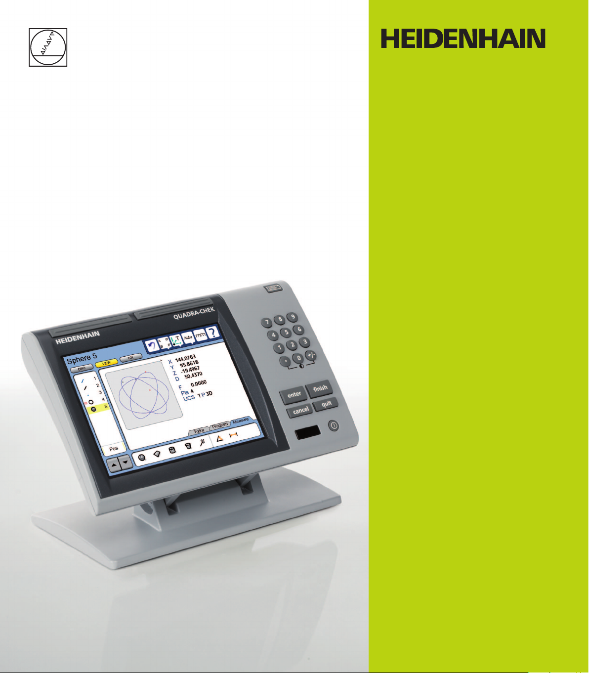
The Quadra-Chek 330 series is a family of
advanced digital readout systems for performing 2, 3 and 4 axis measurements at
very high levels of precision and accuracy.
Dimensional inspection of components can
be made using CMM touch probe systems as
part of in-line production activities or final
quality inspection.
Feature points are entered using fixed, indexing or friction touch probes. Feature type can
automatically be determined by the system
using Measure Magic technology. Level and
skew compensation can be performed on mis-
aligned parts prior to measurements to eliminate
the need for time-consuming fixturing.
1
Overview
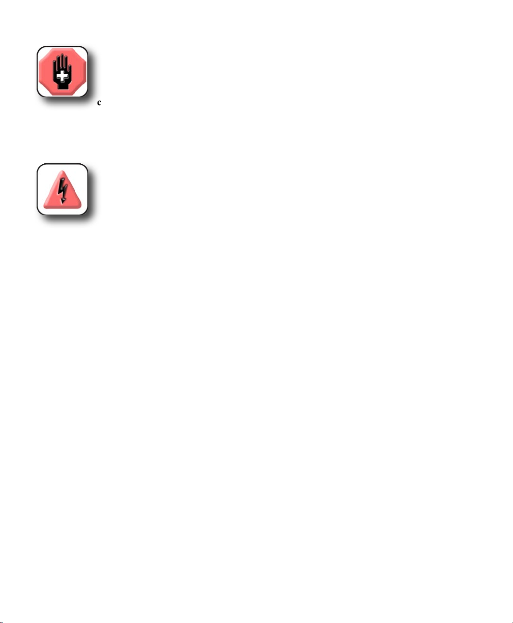
The intuitive interface will be familiar to users of the QC-200 and other Metronics digital readouts. Operators will find the QC-330 easy to understand and use thanks to the large color touch screen LCD display.
The color LCD displays alphanumeric and graphic information for the current measurement, part features
and measurement data clearly on one screen, eliminating the need to page or scroll or navigate for information.
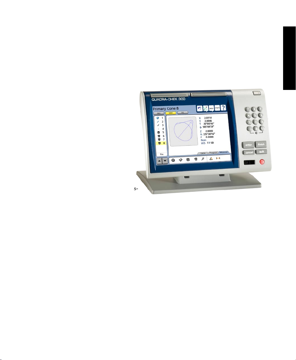
Touch screen controls select the feature to be measured, change operating and display modes, zero axes,
and configure setup parameters. Touch screen controls change to support measurement-specific functions
displayed on the LCD screen.
Front panel keys enter numeric data, turn the LCD on or off and send data to a printer or computer. Two
wide keys located over the LCD can quickly be pressed without looking at the front panel to initiate
frequently used functions programmed by the user. All front panel keys provide tactile sensory feedback,
and key-press operations can be configured to generate an audible sound.
Page 16
2
QC-300 Series User’s Guide
Wide keys
Print/Send data
Touch screen
controls
Numeric keypad
Command keys
Color touch
screen
LCD ON/OFF
Speaker and external speaker jack outputs are provided that can be adjusted for quiet or noisy environments. Ear phones can be plugged into the external speaker jack to facilitate silent operation in quiet
environments.
Sequences of key-presses and touch probe contacts used to perform measurements can be recorded and
stored as programs. These programs can be replayed later to perform complete measurement sequences.
Sequences can be as simple as measuring a line, or can be expanded to include skew adjustment, datuming,
the measurement of multiple features, tolerancing and printing reports of measurement results.
Measurement results can be saved to a USB flash drive, transmitted to a PC over the RS-232 port or printed
on a USB printer.
Page 17
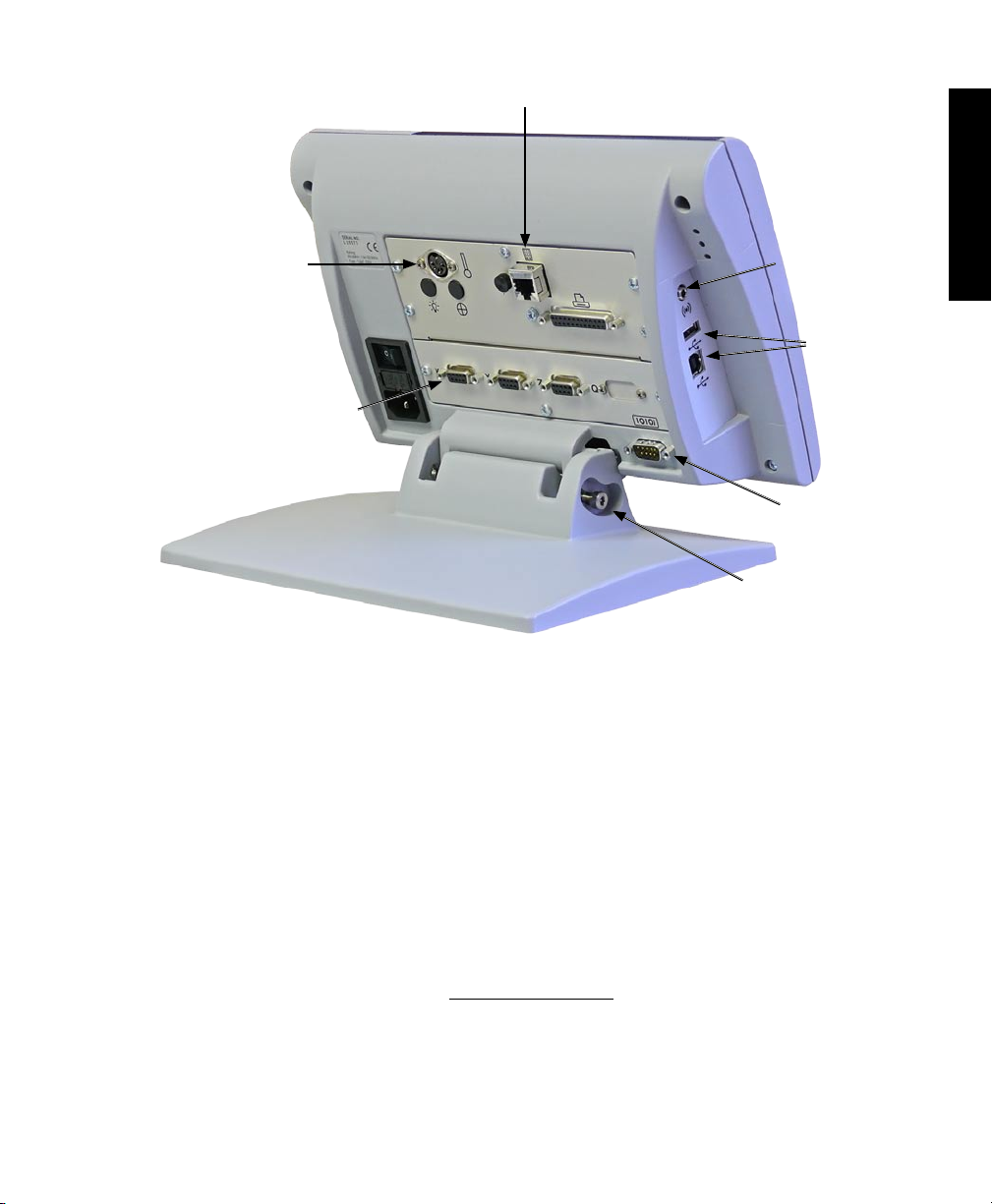
Description of QC-330 Features
External footswitch
3
1
Overview
Touch probe
input
Encoder inputs
The compact ergonomic design and adjustable-tilt front panel of the QC-330 allow users to locate and
mount the instrument in a wide variety of environments that accommodate nearly any viewing requirement. The tilt front panel can be adjusted and secured in any convenient position. Rubber feet on the
bottom prevent slipping when the system is not permanently bolted to a work surface using the bolt holes
provided in the bottom of the mounting stand.
Speaker jack
USB ports
RS-232 port
Tilt adjust
Jacks are provided for an optional foot switch or hand switch. All the optional accessories for the QC-330
are shown in detail at the rear of this guide in Chapter 13: Options.
Page 18

4
QC-300 Series User’s Guide
Page 19
Chapter 2:
Installation
The QC-330 is easy to install in a variety of basic and advanced measurement applications. This chapter
describes how to unpack and install the QC-330. Repackaging instructions are also included for return
shipments and for distributors and OEM customers that are configuring a QC-330 and shipping it to an
end-user.
Unpacking the QC-330
Carefully remove the contents of the shipping carton.
NOTE
Save the carton and packaging materials in case future return shipment becomes
necessary.
5
2
Installation
Inspect the components listed below for shipping damage. The contents of the carton includes:
• QC-330 instrument • Mounting stand and hardware
• Power cord • Warranty registration card
Shipments of other optional equipment in separate cartons might include:
• RS-232 serial cable • QC-Wedge software
• Foot switch or hand switch
If any components were damaged in shipment, save the packaging materials for inspection and contact
your shipping agent for mediation. Contact your Metronics distributor for replacement parts.
Page 20
6
QC-300 Series User’s Guide
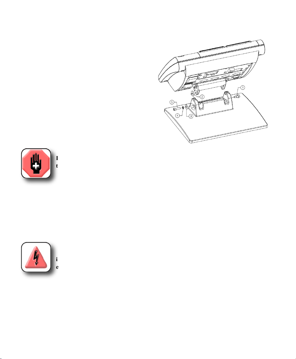
Assembling the mounting stand
The QC-330 is secured to the swivel slots of the mounting stand by a shoulder
screw, a cap screw and associated washers.
Assemble the QC-330 to the mounting stand as shown.
Tighten the shoulder screw (1), and then tighten the cap
screw (5) and washers (3 & 4) so that the QC-330 will
be secure when adjusted to the desired tilt position.
Safety considerations
The QC-330 is completely enclosed and no hazardous outputs can come in contact with the user. Safety considerations
are related to power connections and physical mounting.
WARNING
If the QC-330 falls from its mounting location, serious personal injury or damage to
the equipment can result.
Power cord and plug
Do not locate the power cord where it can be walked on or will create a tripping hazard. Connect the 3-wire
power plug to only a 3-wire grounded outlet. Never connect 2-wire to 3-wire adapters to the power cord
or remove the third ground wire to fit the plug into a 2-wire electrical outlet. Modifying or overriding the
third-wire ground creates a safety hazard and should not be permitted.
DANGEROUS VOLTAGE
Always disconnect the power cord from the source of AC power before unplugging
it from the QC-330 power connector. The AC voltage available at electrical outlets is
extremely dangerous and can cause serious injury or death.
Electrical wiring and connections
Perform regular inspections of all connections to the QC-330. Keep connections clean and tight. Locate
cables away from moving objects. Do not create tripping hazards with power cords, input/output cables or
other electrical wiring.
Use shielded cables to connect to the serial RS-232 port. Make certain that cables are properly terminated
and firmly connected on both ends.
Page 21
Safety and Power
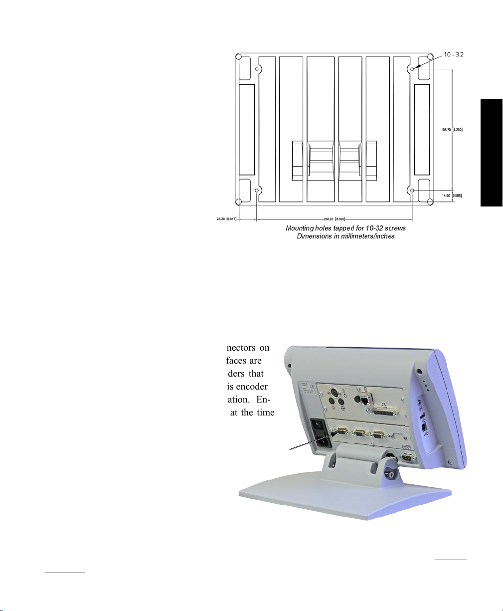
Location and mounting
Rest the QC-330 on a flat, stable surface,
or bolt it to a stable surface from the bottom using four 10/32 screws fastened in
the pattern shown at the right.
Power surge suppressor
Connect the QC-330 to power through a high-quality power surge suppressor. Surge suppressors limit the
amplitude of potentially damaging power line transients caused by electrical machinery or lightning. When
a surge suppressor is not used, power line transients can corrupt system memory or damage circuits.
7
2
Installation
Connecting axis encoders
Axis encoders are attached to interface connectors on
the rear of the QC-330. Many encoder interfaces are
available to match the wide variety of encoders that
can be used with the QC-330. The type of axis encoder
connectors will vary depending on the application. En-
coder inputs are specified as analog or TTL at the time
of purchase and cannot be changed in
the field.
X, Y, Z and Q axis
1 Verify that the QC-330 is off.
2 Connect the axis encoders tightly
to their connectors. An axis label is provided near each connector. Do not overtighten
the connector screws.
Encoder input parameters must be configured later using the Encoder setup screen. Please refer to Chapter
10: Setup for details regarding encoder setup.
input connectors
Page 22
8
QC-300 Series User’s Guide
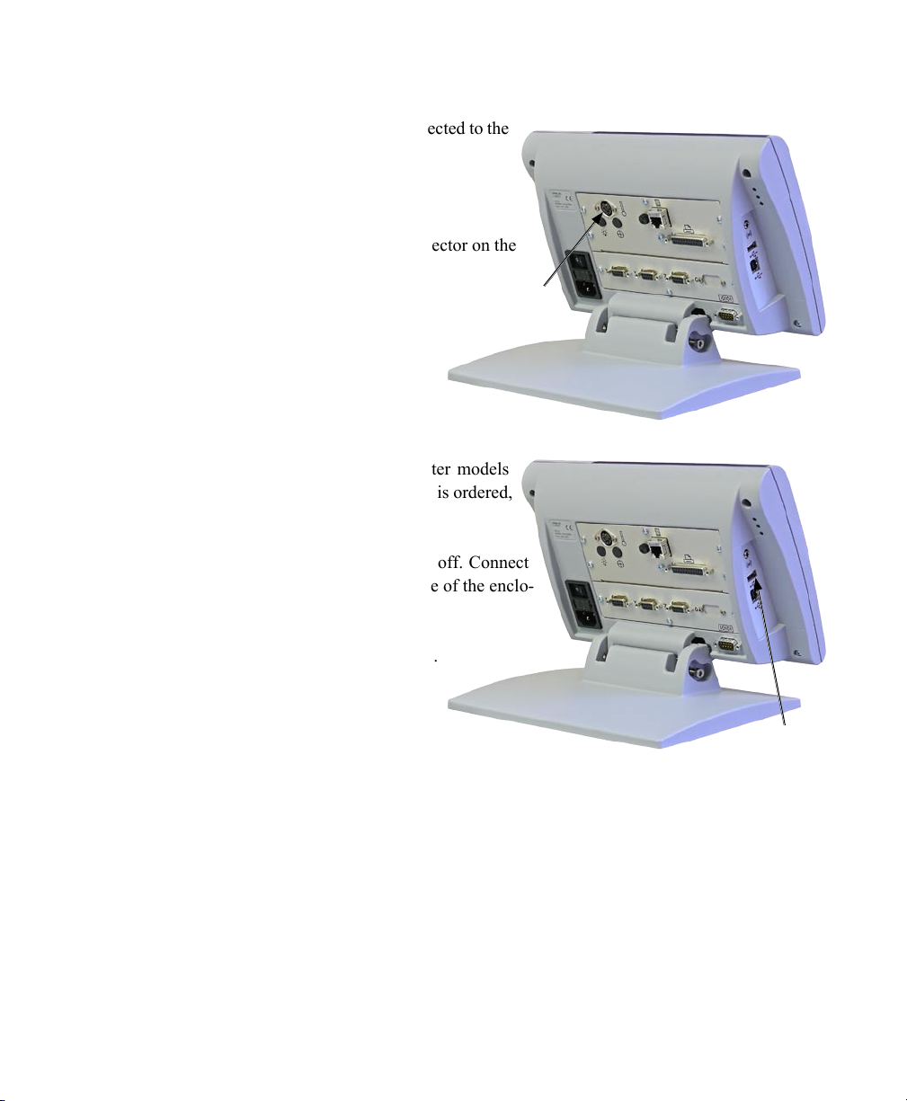
Connecting the touch probe input
The fixed or manually indexed touch probe is connected to the
Renishaw® connector on the rear of the QC-330.
1 Verify that the QC-330 is off.
2 Connect the touch probe to the Renishaw connector on the
rear panel.
Touch probe
connector
Connecting a printer
The QC-330 supports certain USB printers. Printer models
should be specified by Metronics when the QC-330 is ordered,
or approved by Metronics later.
1 Verify that the QC-330 and printer power are off. Connect
the USB printer to the USB Type A port on the side of the enclo-
sure.
2 Make sure the USB cable plug is fully inserted.
USB printer
port
Page 23
Connections
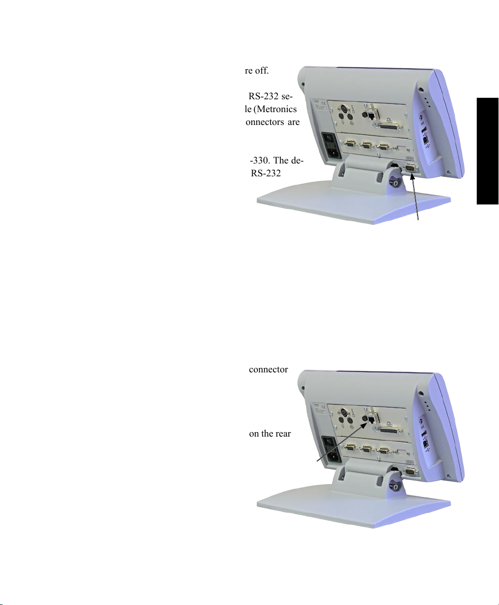
Connecting a computer
1 Verify that the QC-330 and computer power are off.
2 Connect a computer COM port to the QC-330 RS-232 se-
rial port using a standard straight-through serial cable (Metronics
part number 11B12176). Make sure the cable connectors are
tight, but do not overtighten the connector screws.
3 Apply power to the computer, and then the QC-330. The de-
fault QC-330 settings for communication over the RS-232
serial port are shown here.
• Baud rate: 1200
• Parity: None
• Data bits: 7
• Stop bits: 1
• Flow control: Hardware
4 Launch the computer application that will be used to communicate with the QC-330, and configure the
communication properties of the COM port to match those of the QC-330.
RS-232 serial port
connector
9
2
Installation
Connecting an optional footswitch
The optional foot switch is connected to the RJ-45 connector
on the rear of the QC-330.
1 Verify that the QC-330 is off.
2 Connect the foot switch to the RJ-45 connector on the rear
connector panel.
Footswitch connector
Page 24
10
QC-300 Series User’s Guide
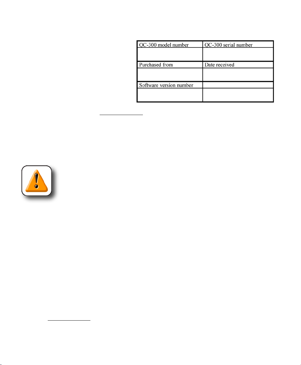
Warranty registration form
The warranty registration form included in
the shipping carton should be completed and
mailed as soon as possible. Also record the
purchase and warranty information here so
that it will be readily available later to support
any necessary interactions with distributor or
factory technical support personnel.
The software version can be found in the
Hardware setup screen. Refer to Chapter 10: Setup for screen descriptions.
Repackaging for shipment
Repackage the QC-330 in the original packaging as received from the factory, or equivalent. It is not
necessary to ship the base when shipping the QC-330 for repair.
CAUTION
The original packaging must be duplicated and the LCD must be inserted face-up to
prevent damage to the LCD screen.
Pay special attention to the following instructions:
1 Connect any loose mounting hardware to the QC-330 instrument
2 Repackage the foam and cardboard carton inserts as originally shipped from the factory.
3 Place the QC-330 into shipping carton with the LCD facing up.
4 Replace the warranty card and slip sheets found at the top of the carton. The “Before you begin” slip
sheet should be inserted last.
What’s next?
Proceed to Chapter 10: Setup to configure your QC-330 for use. Follow the instructions for Minimum Setup
requirements.
Page 25
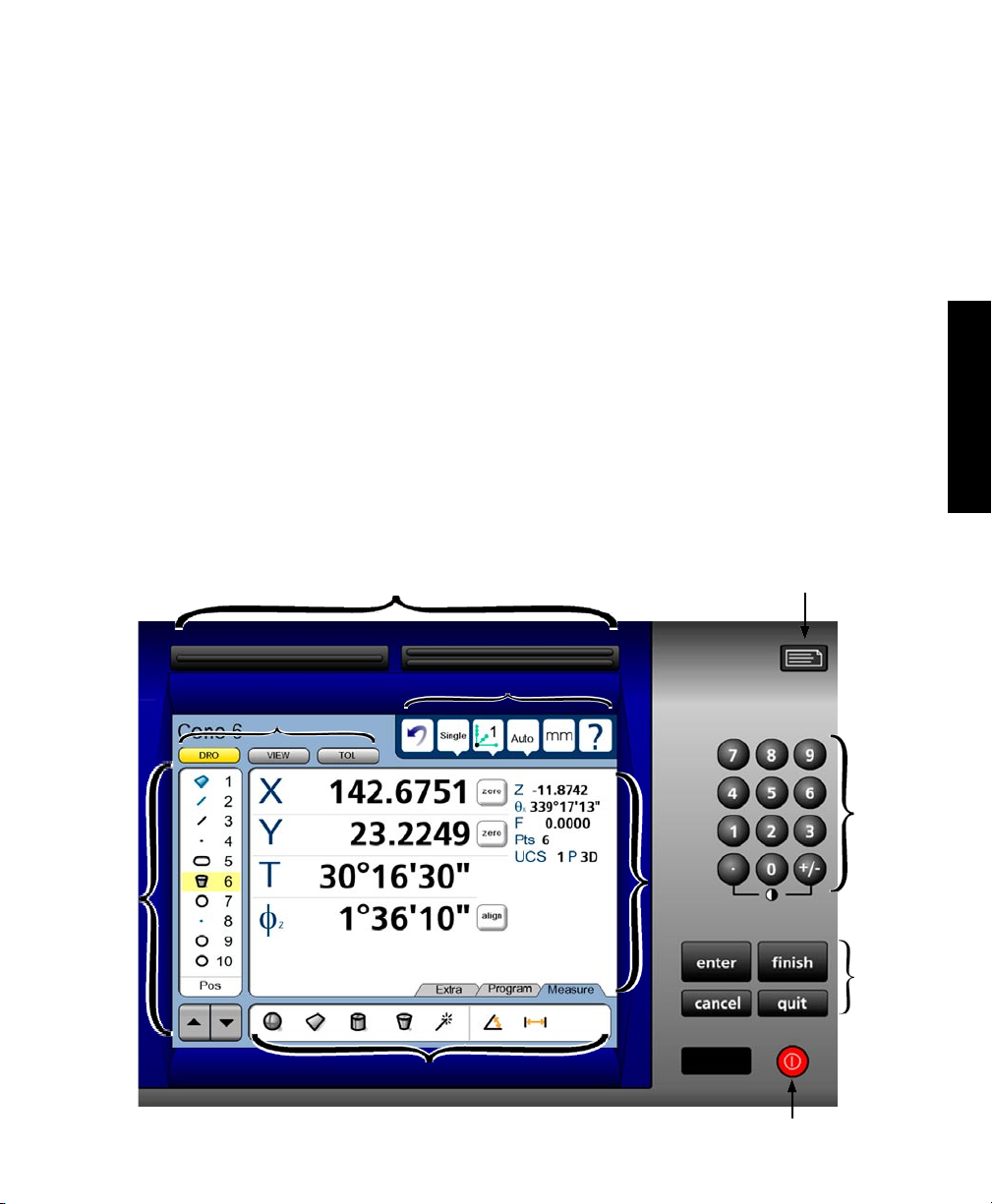
Chapter 3:
User Interface
The QC-330 user interface consists of hardware front panel buttons and number keys that work in cooperation with software menus, buttons, and data fields shown on the color LCD touch screen. The hardware/
software interface is divided into the function areas listed and shown below.
• Screen functions • Command buttons and wide keys
• Data display • Number keys
• Measurement functions • LCD ON/OFF or delete features
• Feature list • Printing reports and sending data
• System functions
Screen functions
Wide keys
System functions
Printing reports
and sending data
11
3
User Interface
Feature
list
Number
keys
Data
display
Command
buttons
Measure functions
LCD ON/OFF
and delete features
Page 26
12
QC-300 Series User’s Guide
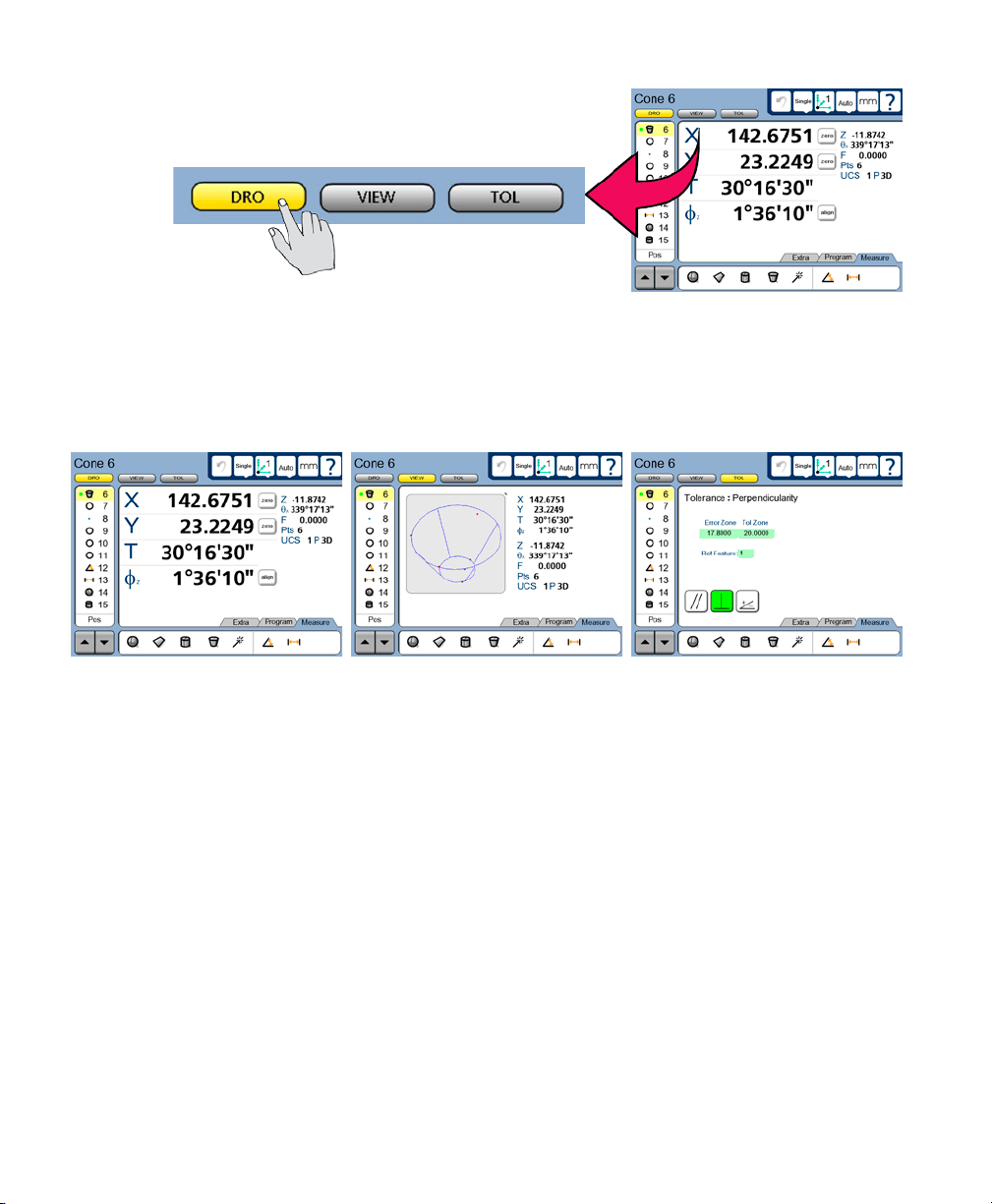
LCD Screen functions
The LCD functions are used to select screens that support operator
activities.
Touch a button to select the desired screen.
• DRO Displays the digital readout
• VIEW Displays the selected feature’s data cloud and physical geometry
• TOL Displays the tolerance screens for entering and editing tolerances
DRO screen VIEW screen TOL screen
Page 27
LCD Screen Functions
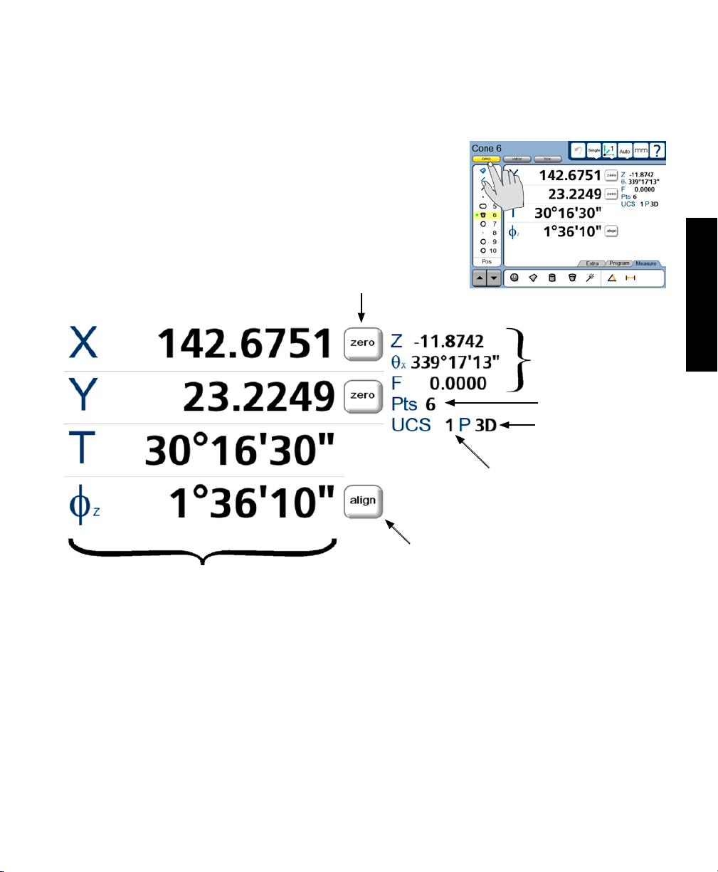
Data display
Data is displayed on the DRO, View and Tol screens.
DRO screen
Press the DRO button to display the DRO screen. Measurement data,
reference frame, projection, part alignment controls and part datum
controls are shown on the DRO screen.
Part datum
controls
13
3
User Interface
Feature data:
minor coefcients
Data points
Projection
Feature data:
major coefcients
Reference frame ID
Part alignment control
Page 28
14
QC-300 Series User’s Guide
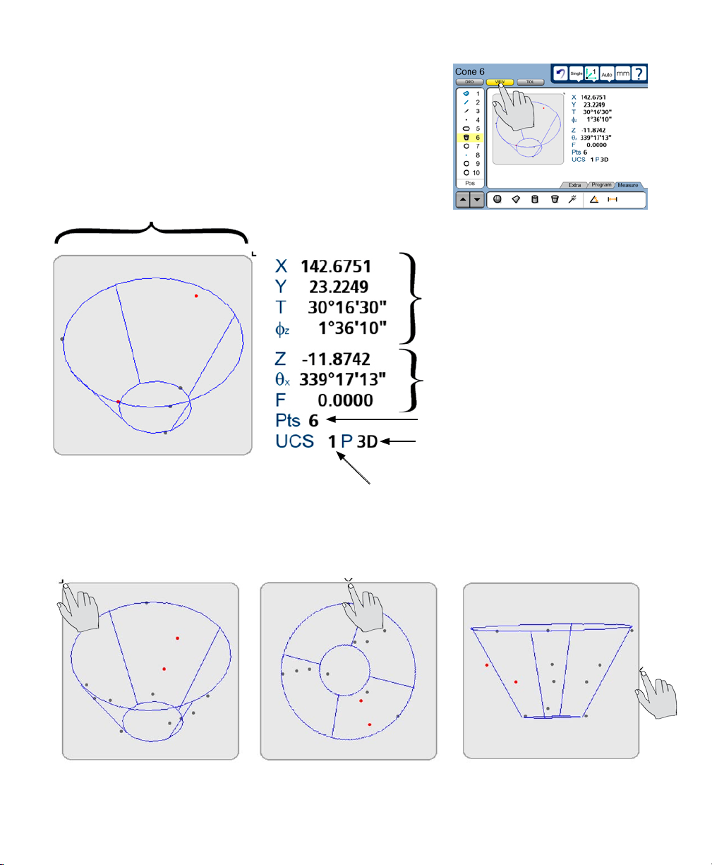
View screen
Press the VIEW button to display the VIEW screen. Measurement
data, reference frame, projection and an image of the data cloud and
resulting feature geometry are shown on the View screen.
Data cloud and
feature geometry
Feature data:
major coefcients
Feature data:
minor coefcients
Data points
Projection
Reference frame ID
The view of the feature geometry is rotated by touching center or corner points at the edge of the image or
by touching and dragging across the screen.
Page 29
LCD Screen Functions
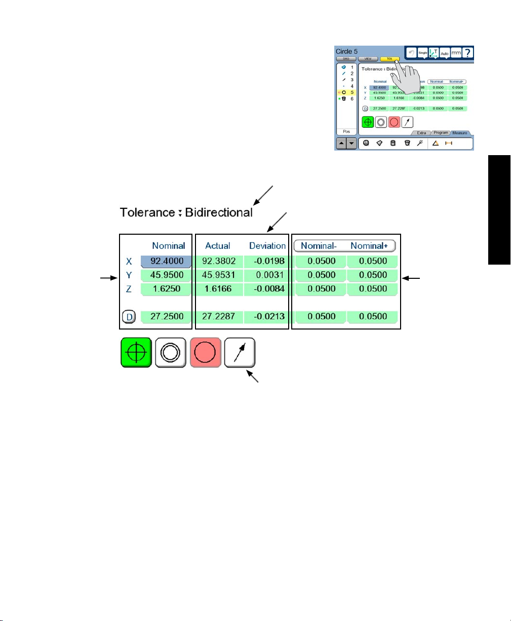
TOL screen
Press the TOL button to display the Tolerance screen. Tolerance data,
tolerance type selections and tolerance specification fields are shown
on the TOL screen.
15
Specication
of nominal
values
Tolerance
type
Measurement
results
Tolerance type selection controls
3
User Interface
Tolerance
specications
Page 30
16
QC-300 Series User’s Guide
Measurement functions
The measurement functions are divided into three tabbed areas:
• Measure Select a measurement type, such as circle, line or sphere
• Program Record, edit or play back a program of measurement steps
• Extra Send data to the RS-232 port
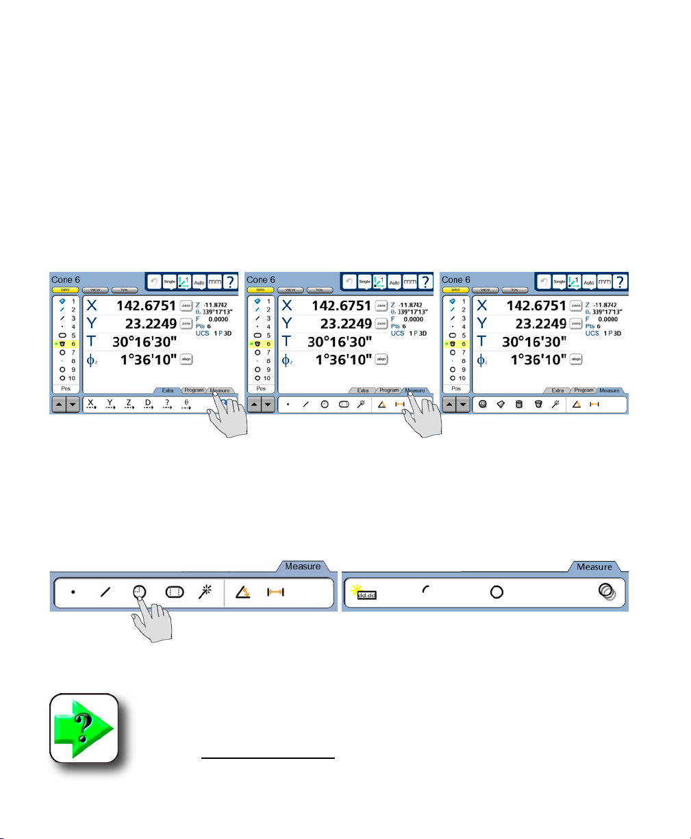
Selecting a measurement type
Measurement types are selected from the Measure tab. Touch the Measure tab repeatedly to display icons
in the measure tab for the different 2D and 3D measurement types.
Touch the Measure tab to display
measurement types...
Touch a measure icon to select the desired measurement type. In some cases, such as when selecting
circles and slots, related measurement types will also be presented as shown in this example of touching
the circle icon to display the arc measure type.
Touching the circle measure icon... displays circle and arc measurement types
NOTE
Details regarding performing measurements and the use of measurement tools are
provided in Chapter 6: Measuring.
then touch the Measure tab repeatedly to alternately display 2D and 3D
measurement types
Page 31

Measurement Functions
Accessing programs
Programming functions are accessed from the Program tab. Touch the Program tab to display a list of
programs and show programming tools. Details regarding programming and the use of programming tools
are provided in Chapter 8: Programming.
Touch the Program tab... to display programs and programming tools
17
3
User Interface
Touch a program tool icon to play, record, edit, copy, stop or add a user message to a measurement program. In the Edit mode, completed program steps are shown in the feature list.
Programming tools shown before recording Programming tools shown during recording
Run a program Run a program
Record a program Stop recording
Open edit mode Open edit mode
Copy a program Include user message
Select a drive
Copy to drive
Page 32

18
QC-300 Series User’s Guide
Sending data to a computer from the Extra tab
Touch a data icon shown in the Extra tab to send the corresponding data element for the current position
or selected feature to a computer over the RS-232 serial port. Touch the Extra tab again to display more
data choices.
Touch the Extra tab... to display the data choice icons
NOTE
The Extra tab sends data only to the RS-232 port and is configured in the Display
setup screen. Please refer to Chapter 10: Setup for details.
The data sent to the RS-232 serial port always correspond to the information displayed in the DRO screen.
The information types are shown in the upper-left corner of the screen and are:
• Current position (no feature selected)
• Feature measurement (feature selected)
NOTE
Touching an icon for an inappropriate data type produces no result. For example,
touching the diameter icon when a circle feature is selected in the feature list sends
diameter data to the serial port, however, touching the diameter icon when a line is
selected produces no result.
The Extra tab is typically used to send abbreviated data to the RS-232 serial port since complete reports or
screens of data can be sent using the Print function described in Chapter 10: Setup. However, a complete
data set can be sent for a feature from the Extra tab by touching the required series of icons in succession.
The transmission of data to the serial port from the Extra tab can be included in programs, like any other
measurement, tolerancing or reporting activity.
Page 33

Measurement Functions
Extra tab functions
Space menu insert
The space insert is included in the Extra tab to separate control functions into groups on the tab.
Divider line menu insert
The divider line insert is included in the Extra tab to separate control functions into groups on the tab
without using a space insert.
19
Transmit feature data
When the user touches any transmit data
icon, the corresponding measurement
data will be transmitted to the RS-232 serial port for the feature highlighted in the feature list.
Data prompt function
The data prompt function is included in the Extra tab to send a user-defined measurement such as
X position, Y position, radius or angle to the RS-232 serial port. When the user touches the data
prompt function, a prompt message is displayed and the user selects the desired piece of measurement data
to be transmitted.
Rotate about axis function
When the user touches the rotate about axis function, an axis dialog box is displayed for axis selection and rotation angle entry.
Multiple Extra tabs
Multiple Extra tabs might be necessary to display all the Extra tab functions available. Touch the Extra tab
repeatedly to access multiple tabs.
3
User Interface
Touch the Extra tab...
to show alternate functions
Page 34

20
QC-300 Series User’s Guide
Feature list
The feature list provides access to all features that have been measured,
constructed or created. Features are selected by touching them in the
feature list, and are then viewed or toleranced in other screens.
When the feature list contains too many entries to be displayed on a
single screen, the arrow keys at the bottom of the list are used to scroll
up or down through all features.
Selected features... can be viewed... or toleranced in other screens
When editing programs, program steps are also shown in the feature
list.
Page 35

Feature List and System Functions
21
System functions
System functions support a wide variety of measurement and setup
activities. System functions include:
• Undo
• Probe holder
• Reference frame
• Projection
• Unit of measure (mm/Inch)
• Setup
Undo
The undo function is very similar to the Windows® undo function and erases the last measurement
or feature list activity. The Undo function only erases the last step, sequences of steps cannot be
erased using undo.
Probe holder
The probe holder button shows which of the touch probes has been
selected. Touching the probe holder button displays the probe Properties dialog box which shows probe size, offsets and controls for probe
qualification and data reset.
System functions
3
User Interface
Reference frame
The reference frame button shows the active reference frame. Touching the reference
frame button displays a drop down menu of previously saved reference frames. Any of
the previously saved reference frames can be selected.
Page 36

22
Projection
The projection button shows the active 2D or 3D projection plane or coordinate system.
Touching the projection button displays a drop down menu of available 2D projection
planes or 3D coordinate systems that can be selected. Auto instructs the system to choose
the projection plane or coordinate system that best matches the current measurement
activities.
Unit of measure
The unit of measure button toggles the linear unit of measure between metric and English. Touch the mm/in button to toggle the units of measure.
Setup
The setup button provides access to the system setup screens required for configuring QC-330
measurement and operation. Touch the setup button to display the setup screens. Access to the
setup menu is given through two introductory screens that show the software version, the system
options and a caution regarding the use of setup functions.
QC-300 Series User’s Guide
Setup screen tools will be made available to those who can provide a valid supervisor password.
NOTE
Detailed descriptions of all setup functions and tools are contained in
Chapter 10: Setup.
Page 37

Command Buttons and Wide Keys
Command buttons and wide keys
The command buttons and wide keys are primarily used to support measurement and setup activities.
The command wide keys are duplicates of the Enter and Finish functions which are the most frequently
used command buttons, and can be located and pressed easily by the operator without looking at the front
panel.
Wide keys
23
Enter Finish
Command
buttons
• Enter Enters a point (or points) into a measurement, or enters a value into a measurement
data field, tolerance data field, communication data field or a setup data field
• Finish Completes a measurement, tolerancing or setup session
• Cancel Removes the last point from a measurement, deletes a feature from the feature list,
or removes the last character from a data or text field
• Quit Cancels a measurement in progress, ends a setup session without saving new settings
or ends a programming session
3
User Interface
NOTE
Details regarding the use of the command keys are provided in Chapter 6: Measuring,
and are distributed throughout the remainder of this user guide.
Page 38

24
QC-300 Series User’s Guide
Number keys
The number keys are used to enter data into feature constructions and creations, tolerances, programs, and
setup data fields.
Numbers are entered into data fields in the conventional manner, and can be erased when necessary by
backspacing over them using the Cancel button.
Number
keys
Page 39

Number Keys and LCD On/Off
LCD ON/OFF and deleting
feature data
The LCD screen can be turned off without cycling
power when the QC-330 will be idle for an extended
period and it is desirable to retain the original machine zero encoder references. Press the red LCD
ON/OFF button to toggle the LCD on and off.
25
When the LCD ON/OFF button is pressed, the operator is given the opportunity to turn the LCD off
or to erase all feature data and resume operation
without turning the LCD off. If the operator presses
the Enter key to delete feature data, the system will
ask for confirmation. If confirmation is given, the
feature data and datums will be permanently deleted.
You will be asked to press Enter... and to conrm the delete... then the features will be deleted
CAUTION
Delete feature data only when you have saved the data in a report, transmitted it to
a computer file or are sure that you no longer need them. Once the data are deleted,
they cannot be restored.
3
User Interface
Page 40

26
QC-300 Series User’s Guide
Printing reports and sending
data
Feature data shown on the DRO screen or contained
in the feature list can be printed in reports using the
USB port or sent to a computer over the RS232 serial port. In either case, the printing of reports and
the transmission of measurement data is initiated by
pressing the Print button.
NOTE
Report printing and data transmission are configured in the Print
setup screen described in Chapter 10: Setup. Printing and data
transmission are described in Chapter 9: Communication.
Page 41

Chapter 4:
Quick Start Demonstration
This chapter demonstrates the operation of the QC-330 system. The demonstration is provided as a means
of quickly helping experienced operators to use the system. This demonstration will be most helpful if you
perform the measurements and other activities as you follow along.
The demonstration will use the Metronics 3D Demo part to establish a measurement reference frame,
measure a part feature, apply a tolerance, print a tolerance report and save all these activities as a program
that can be recalled and run again later.
27
4
Quick Start
A 3D Demo part is shipped with each system
When the program is run, the series of required points
will be indicated by a green arrow that moves over the
part outline in the View screen. The user need only
probe locations indicated by the arrow to complete
measurements.
The demonstration will be performed using an indexable probe qualified in the A=0, B=0 position. However, the same measurements could be performed
using any supported touch probe.
Detailed information regarding reference frames is contained in Chapter 6: Measuring. Information regarding tolerancing is contained in Chapter 7: Tolerancing. Report printing is discussed in Chapter 9:
Communication. Information regarding programming is contained in Chapter 8: Programming.
Individual steps are
recorded as a program
Page 42

28
Start recording a program
To record the following activities
as a program:
1 Touch the Program tab to display the program screen and then
touch the Record icon. The text
entry screen will be displayed.
2 Enter a program title and
press the Finish key. The DRO
will be displayed. The measure
icons will also be displayed and
the Program tab will be shown in
red to indicate that programming
is in progress.
QC-300 Series User’s Guide
Establish a reference frame
Perform a level, skew and datum as described in Chapter 6: Measuring. In this example, the resting surface for the part is leveled, the X-axis edge of the part is skewed, and a datum point is constructed from the
Y-axis edge of the part and the skew line.
To level:
Measure the desired part plane and zero the angle and Z values. This will be the projection plane for the
skew measurement and datum point construction. In this example, the X-Y plane is leveled.
To skew:
Measure a line on the X (skew) axis, in the X-Y projection plane, and zero the angle.
To construct a zero datum point:
Measure a line on the Y-axis, in the X-Y projection plane, and construct an intersection point.
These steps and the resulting screen images are shown on the facing page.
Page 43

Quick Start Demonstration
The part reference plane is leveled...
the X-axis edge is skewed...
29
4
Quick Start
the Y-axis edge is measured ...
and a datum is constructed
Page 44

30
QC-300 Series User’s Guide
Measure a feature
In this example, the largest hole in the 3D demo part will be measured. Feature measurements are described in Chapter 6: Measuring.
Measurement data are displayed
Apply tolerances to a feature measurement
In this example, a true position tolerance will be applied to the circle measurement. More information
regarding tolerances is contained in Chapter 7: Tolerancing.
To apply a true position tolerance:
With the circle feature highlighted, touch the Tol screen button, touch the position tolerance icon, select
true position and enter nominal, limit or tolerance values. Error and Deviation values are generated as soon
as the Nominal and Tol Dia values are entered.
Pass/fail results are indicated by green and red colors in the tolerance screen and in the feature list. Pass is
indicated by green, fail is indicated by red in the tolerance screen. Any tolerance failure will be indicated
by a red mark next to the feature in the feature list. A green mark will be displayed in the feature list when
all tolerance tests pass.
Page 45

Quick Start Demonstration
Print a report
To print a report of the current position (Display), the feature list (Report) or tolerances (Tol Report):
1 Verify that the QC-330 is attached to a USB printer as described in Chapter 9: Communication.
2 Verify that the report content and printer formatting are specified correctly in the Print setup screen
described in Chapter 9: Communication and Chapter 10: Setup.
3 Press the Print key while displaying the Current Position in the DRO screen.
More information regarding reports of feature measurement data and QC-330 system settings are contained
in Chapter 9: Communication and Chapter 10: Setup.
Stop program recording
To end a recording session, touch the Program tab to display the programming tools, and then touch the
Stop icon to stop recording the program. The program title will be shown on the left side of the screen.
31
4
Quick Start
The program is now saved and can be edited or run on new parts. Touch the Measure tab to return to the
measure mode of operation and display the DRO.
Running the program
To run a program, touch the Program tab to display the program
screen, select the desired program and then touch the Run (play) icon
to run the selected program.
Page 46

32
QC-300 Series User’s Guide
Page 47

Chapter 5:
Probes
Probe holders supported by the QC-330 include:
• Single • MH8 indexable • MH20i indexable
• Star • MIH indexable • Friction
Single Star MH8 MIH MH20i Friction
33
5
Probes
Probes can be touch probes or hard probes. The choices of probe holder and probe type are made in the
probe setup screen described in Chapter 10: Setup.
Probe qualification
Unqualified probes are indicated by a red probe icon at the top right of the screen. The icon becomes
white when a qualification is performed. Probes must be qualified
before use to determine tips sizes
and offsets.
Probes must be qualified upon startup if:
• There is no repeatable machine zero
• The qualification sphere has been moved
• A friction probe is used
The QC-330 can be configured to initiate a probe qualification automatically upon startup in the probe
setup screen described in Chapter 10: Setup.
Red icon for unqualied probes White icon for qualied probes
Page 48

34
Friction probes must be qualified each time the probe position is changed.
Probe qualification can be performed at any time. A measurement sequence can be interrupted to qualify
a new probe tip or position without invalidating the measurement.
To qualify a probe:
1 Touch the probe icon to display the Selector and Property tabs. The Selector tab
is displayed only for the star and indexable
probes.
2 Select the appropriate indexable probe angles or a star probe tip if a star or
indexable probe is being qualified.
NOTE
Qualify the straight-down (0°, 0°) probe position of star and indexable probes first.
All subsequent probe positions will be referred to this (0°, 0°) position.
QC-300 Series User’s Guide
3 Touch the Properties tab to display the probe
offset and size fields.
4 Touch the Teach button to initiate a probe
qualification. Collect 5 points on the qualification
sphere; 4 around the equator and 1 at the top. Press
the Finish key to complete the qualification session.
The tip size will be shown in the Size field. The X,
Y and Z offsets are also shown, and will be zero for
the straight-down (0°, 0°) reference position. When
other star probe or indexable probe positions are
qualified, X, Y and Z offsets will also be shown.
Only probe tip size is
shown for 0, 0 position
X, Y and Z offsets are
shown for other positions
Page 49

Probing Technique and Auto Change/Teach
35
Probing technique
Probing technique refers to the method of moving CMM
axes and entering point data with a touch probe. Good
probing technique includes the following:
• Approach the surface at a 90° angle
• Approach the surface without direction changes
from a distance of at least 5 mm
• Do not drag the probe across the surface
• Do not probe on a sharp edge or drop the probe off
an edge of the part
Orthogonal approach without changing direction
Auto change/teach function
Star and indexable probe tips or positions can be changed or qualified at the CMM work surface without
touching front panel controls when the Auto change/teach function is enabled in the Probe setup screen as
described in Chapter 10: Setup.
To change or qualify a new star probe tip or indexable probe position:
5
Probes
1 Touch the qualification sphere once with the current (qualified) tip.
2 Touch the qualification sphere a second time with the new star probe tip or the new indexable probe
position. If the new tip or position was previously qualified, the QC-330 will acknowledge the change and
continue gathering feature data. If the new tip or position was not previously qualified, measurements will
be temporarily suspended and a probe qualification will be initiated. When the qualification is complete,
the measurements will be resumed.
Page 50

36
QC-300 Series User’s Guide
Page 51

Chapter 6:
Measuring
Measurements can be performed using single-fixed, star, indexable or friction hard probes or touch probes.
Activities can be limited to probing features, or can include the construction or creation of new features in
addition to probing. However measurements are conducted, the fundamental measurement process and the
tools required to perform measurements remain unchanged. Here’s what you’ll find in this chapter:
Measurement activities.....................................................................................38
The measurement process ................................................................................38
Establishing a reference frame .........................................................................39
Part leveling ..............................................................................................39
Part skew alignment ..................................................................................40
Establishing a datum zero point ................................................................41
Saving the reference frame .......................................................................43
Measuring features ...........................................................................................45
Selecting a projection plane ......................................................................45
Probing features ........................................................................................46
Probing process ..................................................................................48
Probing specific feature types ...................................................................50
Constructing features .......................................................................................61
Duplicate features .....................................................................................61
Extracted features ...................................................................................... 62
Intersection features ..................................................................................62
Relation features .......................................................................................63
Multipoint features ....................................................................................63
Perpendicular/parallel/tangent features .....................................................64
Gage line and circle features .....................................................................65
Creating features ..............................................................................................66
37
6
Measuring
Page 52

38
QC-300 Series User’s Guide
Measurement activities
QC-330 measurement sessions can include two or more of the following activities:
• Establishing a measurement reference • Constructing features
• Probing and measuring features • Creating features
The measurement process
The basic measurement process shown here is identical for all feature types. The details of individual
measurement steps are described in the remaining pages of this section.
Establishing a reference frame Measuring features
Measurement results
are shown in the
feature list
Review part position
and other data on the
LCD screen
NOTE
Tools and controls for probing features and conducting measurements are discussed
in Chapter 3: User Interface, and Chapter 5: Probes.
Touch a measure icon
to begin a feature
measurement
Press the Enter key
to enter a point with a
hard probe
Press the Finish key
to conclude a feature
measurement
Press the Quit key
to cancel a feature
measurement
Press the Cancel
key to delete the last
probed point
Page 53

Establishing a Reference Frame
Establishing a reference frame
A reliable measurement reference must be established before part features can be probed and measured.
This reference frame is created by the user to ensure a level part surface, precise part alignment and accurate datum zero. Reference features are presented in the feature list in blue, other features are presented
in black. Reference frames can be established in any projection plane. The examples included in this
chapter are in the X-Y plane.
Part leveling
When the surface plane of the part is not orthogonal to the measurement axis, small cosine errors can be
generated during the measuring process. These errors are minimized or eliminated by leveling the part.
To level the part:
1 Touch the Measure tab to display the 3D feature measure icons,
and then touch the measure plane
icon.
39
2 Perform the leveling measurement by probing three or more points
distributed across the surface of the desired part plane. Press the Finish
key to complete the level measurement.
3 Touch the Align and Zero buttons to level the plane at the Z = 0 elevation. The reference plane feature
will be shown in blue and the Z-axis value will be zero.
6
Measuring
Page 54

40
QC-300 Series User’s Guide
Part skew alignment
When the part is misaligned (twisted) in the X-Y plane, errors can be generated
during the measurement process. These errors can be eliminated by performing a
skew alignment on the part.
The skew alignment includes a precise measurement of the part misalignment.
Once the misalignment is known to the system, subsequent feature measurements
are automatically compensated to eliminate misalignment errors. Measurement
data in the DRO will reflect measurements of a perfectly aligned part.
To skew the part:
1 Touch the Measure tab and then touch the measure line icon.
2 Measure a line along the reference edge of the part. The X-axis
edge is used in this example.
3 Touch the Align button to
perform a skew on the reference
edge.
The skew line feature will now be shown in blue and the reference angle will be zero degrees.
Page 55

Establishing a Reference Frame
Establishing a datum zero point
The datum zero point is used as the origin of the reference frame. The datum zero point can be positioned in
any location that satisfies the measurement requirements of the user and can be created by probing a point,
but is probably better created by constructing a point from parent features.
It would not be possible to provide a single description of this process for all measurement applications.
However, the concept is illustrated by this example and by the construction techniques described later in
this chapter.
After the part level and part skew are performed, a datum zero point
is constructed at the intersection points of the X-axis (skew axis), and
the Y-axis of the part.
To construct the datum zero point:
1 Touch the Measure Line icon
and then measure a line along the
Y-axis edge of the part.
41
2 Touch the measure point icon and then construct a point at the intersection of the skew and Y-axis
lines by touching (selecting) them in the feature list and pressing the Finish button.
Construct a point for the datum by selecting the skew and Y-axis lines and pressing the Finish key
6
Measuring
Page 56

42
3 Establish the zero datum point
by touching the Zero buttons for
the X and Y axes.
The datum point will be shown in
blue in the feature list and the X-Y
values will be zero.
QC-300 Series User’s Guide
Page 57

Establishing a Reference Frame
Saving the reference frame
Measurements are referred to a temporary reference frame until a new
reference frame is saved. Temporary reference frames are indicated
by a T in the reference frame icon in the upper-right corner of the
screen, and by a T in the UCS (user coordinate system) field of the
DRO.
43
Reference frames must be saved to maintain measurement integrity.
When multiple reference frames are created but not saved, all references are temporary and all measurements are referred to the last
temporary reference frame.
When a new reference frame is saved, the reference frame indications
are given the next number in a sequence that begins at 1. As new
reference frames are created and saved, additional indicator numbers
are assigned and made available to the drop-down menu of reference
frames.
Reference frames can be saved manually or automatically. In either
case, the entire reference frame must be completed before conducting any measurements.
Saving reference frames manually
When reference frames are saved manually, they must be saved immediately after their creation. To save
a reference frame manually:
1 Verify that the reference frame is complete and correct
2 Touch the reference frame icon and then touch the Save icon.
Reference frame
indications
Drop-down menu of
reference frames
6
Measuring
A new reference frame number will be displayed in the reference frame icon.
Page 58

44
Saving reference frames automatically
The QC-330 can be configured to save reference frames automatically in the Measure setup screen, as
described in Chapter 10: Setup.
When configured to auto-save reference frames, the current reference frame is saved each time a new
datum operation is initiated. A new reference frame number is added to the drop-down menu each time a
reference frame is saved.
QC-300 Series User’s Guide
Page 59

Measuring Features
Measuring features
Part features are measured after creating a reference frame by selecting a projection plane (if required) and
then probing points that define the feature’s shape and location.
Selecting a projection plane
Projection planes can be selected by the user or selected automatically by the system and include:
• 3D: No plane is selected
• YZ • ZX • XY
• Auto: The system selects a plane based on
measurement activities
The default projection plane for measurements and constructions
is the level plane used to establish a reference frame. If the level
was performed in the X-Y plane, it is likely that most measurements will be shown in the X-Y projection plane. However, when
Auto is chosen, a projection plane is selected by the system that
best fits the measurement. When 3D is selected, no projection
plane is shown. When a specific projection plane is selected, measurements and constructions are forced into the selected plane.
45
Projection planes are selected from
the drop-down menu and shown
with the measurement data on the
DRO screen.
Projection plane for
current feature
6
Measuring
Drop-down menu of
projection planes
Page 60

46
QC-300 Series User’s Guide
Probing features
Feature points can be probed using Measure Magic or by choosing a specific feature type such as the line or
circle. Measure Magic or measure functions are selected by touching icons in the measure toolbar. Repeatedly touching the measure tab toggles the measure toolbar between 2D and 3D functions. Measurement
results are shown in the Feature list, DRO screen and View screen.
Measure
points
Measure
spheres
Measure
lines
The measure toolbar icons for 2D measurement functions and measure magic
Measure
planes
The measure toolbar icons for 3D measurement functions and measure magic
Measure
circles &
arcs
Measure
cylinders
Measure
slots &
rectangles
Measure
cones
Measure
Magic
Measure
angles
Measure
distances
Probing with Measure Magic
Measure Magic analyzes feature data collected by part probing and automatically determines the feature
type. Measure Magic supports the following feature types in the QC-330:
• Points • Lines • Circles • Arcs • Planes • Cylinders • Cones
When Measure Magic is used, and more than the minimum number of points required to define a feature
type are collected, the feature type can be changed manually by the user if the wrong feature type is assigned.
Measure can be configured to start automatically on the first probe hit in the Measure setup screen as
explained in Chapter 10: Setup.
Page 61

Measuring Features
To probe a feature using Measure Magic, touch the
Measure Magic measure icon (if not configured to
auto-start), probe points on the desired feature and
then press the Finish key.
Probing specific feature types without Measure Magic
When Measure Magic is not used, a measure icon must be touched before a feature type is probed. However, a series of features of the same type can be probed by touching the desired measure icon and then
touching the multiple measurement icon.
Probing a single specific feature type
To probe a single feature without Measure Magic, touch the desired measure icon, probe points on the
feature and then press the Finish key. A measure icon must be touched again to measure the next feature.
In this example a single circle is probed.
When a specific measure function is used to probe
the feature, the feature type cannot be changed once
it is added to the feature list.
Probing multiple specific feature types
To probe a series of features without Measure Magic, touch the desired measure icon, touch the multiple
measurement icon, probe points on each feature pressing the Finish key to conclude each feature measurement. In this example multiple circles are probed.
47
6
Measuring
Touch the circle icon for circle measurements...
When a measure icon is touched to probe a series of similar features, the feature type cannot be changed
once features have been added to the feature list.
and then touch the multiple measurement icon to
measure a series of circle features
Page 62

48
Probing process
The feature probing process is essentially
the same for all feature types.
QC-300 Series User’s Guide
Touch the desired measure icon
Supported feature types
The following feature measurements are supported by the QC-330:
• Points • Slots • Planes
• Lines • Rectangles • Cylinders
• Arcs • Distances • Cones
• Circles • Angles
Features can be probed manually or semi-automatically as part of a program.
NOTE
Manual probing is discussed in Chapter 5: Probes. Semi-automatic probing is discussed in Chapter 8: Programming.
Probe the feature, then press Finish
to complete measurements
Results are displayed in the DRO
and View screens
Page 63

Measuring Features
Backward/forward annotation
Forward annotation is used to specify a required number of probed points for each feature type. Backward
annotation allows the user to probe any number of points beyond the minimum requirement for any feature
type except slots and rectangles.
When using forward annotation, the number of remaining required points is shown at the top left of the
screen. As points are probed this number counts down. Backward annotation simply displays the number
of points as they are entered. Some users prefer forward annotation because it establishes a uniform number of points for feature measurements. For example, forward annotation can be set to require 4 points
when measuring a circle instead of the minimum three.
When forward annotation is used, the system automatically displays the feature after the last required point
is entered. It is not necessary to press the Finish key to conclude forward annotation measurements.
NOTE
Users can toggle between backward and forward annotation and specify the required
points for forward annotation in the Measure setup screen. Please refer to Chapter
10: Setup for more information regarding backward and forward annotation.
49
6
Measuring
Page 64

50
QC-300 Series User’s Guide
Probing specific feature types
While the probing process is essentially the same for all feature types, the minimum number of points
required and the geometric placement of these points are different. The unique requirements for probing
each feature type are described in the remainder of this section.
Probing points
A minimum of one probed point is required to measure a point. Multiple points can be probed and it is considered a benefit to use the
geometric average of many probed locations.
When a single point is probed, Measure Magic will correctly recognize
a point and assign the correct feature. However, when multiple points
are probed, it is possible that the wrong feature type will be assigned.
If the wrong feature type is assigned, it can easily be changed by selecting the correct feature from a menu of alternatives in the DRO
screen.
NOTE
Points must be probed orthogonal to the contact surface for the system to correctly
apply probe tip compensation.
Points must be probed orthogonal
to the contact surface
Touch the feature type...
to display the menu of alternative
types
Probed points are shown in the
View window
Measurement results are shown in the Feature list, View screen and DRO screen. The feature graphic in
the View screen shows the feature and the points used to define it. Errors are shown as whiskers connecting the probed points to the feature. The maximum errors are shown in red and are used in the calculation
of form. The DRO screen shows the feature type, feature position, form error, number of points used,
reference frame and the projection plane. When the minimum required points are probed, the form error
is zero. When more than the minimum are probed, the form error is the sum of the two greatest opposing
error magnitudes.
Page 65

Measuring Features
Probing lines
A minimum of two points are required to measure a line. There is
no practical limit to the number of points that can be probed, and in
general accuracy is increased by probing more points.
When only two points are probed, Measure Magic will correctly recognize a line and assign the correct feature. However, when more
than two points are probed, it is possible that the wrong feature type
will be assigned. If the wrong feature type is assigned, it can easily be
changed by selecting the correct feature from a menu of alternatives
in the DRO screen.
51
In this example, three points are
probed to measure a line
Touch the feature Fit menu...
A best fit algorithm is used to define lines when more than two points are probed. The line fit to the probed
data can also be changed by selecting the desired fitting algorithm from the Fit menu in the DRO screen.
Please refer to Chapter 12: Reference Materials for details regarding the fitting algorithms.
Measurement results are shown in the Feature list, View screen and DRO screen. The feature graphic in
the View screen shows the feature and the points used to define it. Errors are shown as whiskers connecting the probed points to the feature. The maximum errors are shown in red and are used in the calculation
of form. The DRO screen shows the feature type, feature position, angular orientation of the line, form
error, number of points used, reference frame and the projection plane. When only two points are probed,
the form error is zero. When more than two points are probed, the form error is the sum of the two greatest
opposing error magnitudes.
to display the menu of alternative
types
Probed points are shown in the
View window
6
Measuring
Page 66

52
QC-300 Series User’s Guide
Probing circles
A minimum of three probed points are required to measure a circle.
There is no practical limit to the number of points that can be probed,
and in general accuracy is increased by probing more points.
When 185 degrees or more of the circle is probed, Measure Magic will
correctly recognize the circle and assign the correct feature. However,
when less than 185 degrees is probed, it is likely that Measure Magic
will assign the arc feature to the data. If the wrong feature type is assigned, it can be changed by selecting the correct feature from a menu
of alternatives in the DRO screen.
In this example, three points are
probed to measure a circle
Touch the feature type...
to display the menu of alternative
types
Probed points are shown in the
View window
A best fit algorithm is used to define the circle when more than three points are probed. The circle fit to the
probed data can also be changed by selecting the desired fitting algorithm from a menu in the DRO screen.
Please refer to Chapter 12: Reference Materials for details regarding the fitting algorithms.
Measurement results are shown in the Feature list, View screen and DRO screen. The feature graphic in
the View screen shows the feature and the points used to define it. Errors are shown as whiskers connecting the probed points to the feature. The maximum errors are shown in red and are used in the calculation
of form. The DRO screen shows the number of points used, the radius, diameter, coordinate location of
the center of the circle, form error reference frame and the projection plane. When only three points are
probed, the form error is zero. When more than three points are probed, the form error is the sum of the
two greatest opposing error magnitudes.
Page 67

Measuring Features
Probing arcs
A minimum of three probed points is required to measure an arc. There
is no practical limit to the number of points that can be probed, and in
general accuracy is increased by probing more points.
When the arc is less than 185 degrees, Measure Magic will correctly
recognize the arc and assign the correct feature. However, when the
arc is 185 degrees or more, it is likely that Measure Magic will assign
the circle feature type to the data. If the arc is shallow, Measure Magic
might mistakenly assign a line feature. If the wrong feature type is
assigned, it can easily be changed by selecting the correct feature from
a menu of alternatives in the DRO screen.
53
In this example, three points are
probed to measure an arc
Touch the feature type...
A best fit algorithm is used to define the arc when more than three points are probed. The arc fit to the data
can also be changed by selecting the desired fitting algorithm from a menu in the DRO screen. Please refer
to Chapter 12: Reference Materials for details regarding the fitting algorithms.
Measurement results are shown in the Feature list, View screen and DRO screen. The DRO screen shows
the number of points used, the radius and diameter of the arc, the coordinate location of the center of the
arc, form error, reference frame and the projection plane. The feature graphic in the View screen shows
the feature and the points used to define it. Errors are shown as whiskers connecting the probed points
to the feature. The maximum errors are shown in red and are used in the calculation of form. When only
three points are probed, the form error is zero. When more than three points are probed, the form error is
the sum of the two greatest opposing error magnitudes.
to display the menu of alternative
types
Probed points are shown in the
View window
6
Measuring
Page 68

54
Probing slots and rectangles
Five probed points are required to measure a slot or rectangle. The five
points must be probed in a clockwise or counterclockwise sequence.
As shown here, the correct pattern of points probed is:
• Two points well distributed along one long side, followed by
• One point on the closest end, followed by
• One point on the approximate center of the second long side,
followed by
• The last point on the remaining end
CAUTION
Probing a different sequence of points, or probing out of either clockwise or counterclockwise order will result in erroneous slot measurements.
Measure Magic does not recognize slots or rectangles and will assign the wrong feature type to the data.
The feature must be changed by selecting a slot or rectangle from a menu of alternatives in the DRO
screen.
QC-300 Series User’s Guide
The required ve points can be
probed in either direction
Touch the feature type...
Measurement results are shown in the Feature list, View screen and
DRO screen. The View screen shows the feature and the points used
to define it, the number of points probed, the coordinate location of the
center of the slot or rectangle, the length, the width, the angle of the
center line with respect to the skew axis, the reference frame and the
projection plane.
and change the feature...
to a slot (or rectangle)
Page 69

Measuring Features
Probing angles
A minimum of four probed points are required to measure an angle.
The points must be probed as two lines that form an angle. The number
of points on the first leg of the angle must equal the number on the second leg. There is no practical limit to the number of points that can be
probed, and in general accuracy is increased by probing more points.
To probe an angle:
The number of points must be the
1 Probe (n) points on the first leg
2 Press the Finish key
3 Probe (n) points on the second leg
4 Press the Finish key
The included angle is shown as the default measurement result, however, the angle type can be changed by
selecting the desired angle type from a menu of alternatives in the DRO screen
same for both legs
55
Included angle 360 - angle 180 - angle 180 + angle
The View screen shows the feature and the points used to define it, the coordinate location of the angle, the
angle orientation to the skew axis, the reference frame and the projection plane.
6
Measuring
Page 70

56
Probing distances
Two probed points are required to measure a distance. Measure Magic
can not be used to measure a distance.
Measurement results are shown in the Feature list, View screen, and
the DRO screen.
The View screen shows the feature
and the points used to define it, the
X and Y axis displacements the
distance vector between features,
the reference frame and the projection plane.
QC-300 Series User’s Guide
Page 71

Measuring Features
Probing planes
A minimum of three probed points are required to measure a plane.
There is no practical limit to the number of points that can be probed,
and in general accuracy is increased by probing more points.
A best fit algorithm is used to define the plane when more than three
points are probed. The plane fit to the probed data can also be changed
by selecting the desired fitting algorithm from a menu in the DRO
screen. Please refer to Chapter 12: Reference Materials for details regarding the fitting algorithms.
57
Touch the feature type...
Measurement results are shown in the Feature list, View screen and DRO screen. The feature graphic in
the View screen shows the feature and the points used to define it. Errors are shown as whiskers connecting the probed points to the feature. The maximum errors are shown in red and are used in the calculation of
form. The View screen shows location and angular displacement (shown below), form error, the number of
points used, reference frame and the projection plane (3D). When
only three points are probed, the form error is zero. When more
than three points are probed, the form error is the sum of the two
greatest opposing error magnitudes.
The angular displacements in the coordinate system orientation
shown here for a plane are designated as:
• Phi(Z) The angular displacement of the plane’s axis
from the reference frame’s Z-axis
• Theta(X) The angular displacement of the X-Y
projection of the plane’s axis from
the reference frame’s X-axis
to display the menu of alternative t
algorithms
Probed points are shown in the
View window
6
Measuring
Page 72

58
QC-300 Series User’s Guide
Probing cylinders
A minimum of six probed points are required to measure a cylinder.
The points must be probed beginning with two sets of three points; one
set of three at the top and another at the bottom of the cylinder. After
the initial six points, there is no practical limit to the additional number
of points that can be probed, and in general accuracy is increased by
probing more points. The first six points can be probed: three at the
top, then three at the bottom, or in the reverse order. Additional points
can be probed anywhere on the cylinder surface.
If the feature type is not interpreted correctly by Measure Magic, it can
be changed to a cylinder when more than six points are probed.
Touch the feature type...
to display the menu of alternative
feature types
Points can be probed starting at the
top or at the bottom
Probed points are shown in the
View screen
Measurement results are shown in the Feature list, View screen and DRO screen. The feature graphic in
the View screen shows the feature and the points used to define it. Errors are shown as whiskers connecting the probed points to the feature. The maximum errors are shown in red and are used in the calculation
of form. The View screen shows location and angular displacement (shown below), form error, the number
of points used, reference frame and the projection plane (3D). When
only six points are probed, the form error is zero. When more than
six points are probed, the form error is the sum of the two greatest
opposing error magnitudes.
The angular displacements in the coordinate system orientation
shown here for a plane are designated as:
• Phi(Z) The angular displacement of the cylinder’s axis
from the reference frame’s Z-axis
• Theta(X) The angular displacement of the X-Y
projection of the cylinder’s axis from
the reference frame’s X-axis
Page 73

Measuring Features
Probing cones
A minimum of six probed points are required to measure a cone. The
points must be probed beginning with two sets of three points; one
set of three at the top and another at the bottom of the cone. After the
initial six points, there is no practical limit to the additional number
of points that can be probed, and in general accuracy is increased by
probing more points. The first six points can be probed: three at the
top, then three at the bottom, or in the reverse order. Additional points
can be probed anywhere on the cone surface.
59
If the feature type is not interpreted correctly by Measure Magic, it can
be changed to a cone when more than six points are probed.
Touch the feature type...
Measurement results are shown in the Feature list, View screen and DRO screen. The feature graphic in
the View screen shows the feature and the points used to define it. Errors are shown as whiskers connecting the probed points to the feature. The maximum errors are shown in red and are used in the calculation
of form. The View screen shows location and angular displacement (shown below), form error, the number
of points used, reference frame and the projection plane (3D). When
only six points are probed, the form error is zero. When more than
six points are probed, the form error is the sum of the two greatest
opposing error magnitudes.
to display the menu of alternative
feature types
Points can be probed starting at the
top or at the bottom
Probed points are shown in the
View screen
6
Measuring
The angular displacements in the coordinate system orientation
shown here for a plane are designated as:
• Phi(Z) The angular displacement of the cone’s axis
from the reference frame’s Z-axis
• Theta(X) The angular displacement of the X-Y
projection of the cone’s axis from
the reference frame’s X-axis
Page 74

60
QC-300 Series User’s Guide
Probing spheres
A minimum of four probed points are required to measure a sphere.
The points can be probed in any order. After the initial four points,
there is no practical limit to the additional number of points that can
be probed, and in general accuracy is increased by probing more
points. The first three points should be probed around the equator,
and the last point at the top. Additional points can be probed anywhere on the sphere surface.
If the feature type is not interpreted correctly by Measure Magic, it can
be changed to a sphere when more than four points are probed.
Touch the feature type...
to display the menu of alternative
feature types
Points can be probed in any order
Probed points are shown in the
View screen
Measurement results are shown in the Feature list, View screen and DRO screen. The feature graphic in
the View screen shows the feature and the points used to define it. Errors are shown as whiskers connecting the probed points to the feature. The maximum errors are shown in red and are used in the calculation
of form. The View screen shows location and angular displacement (shown below), form error, the number
of points used, reference frame and the projection plane (3D). When only four points are probed, the form
error is zero. When more than four points are probed, the form error is the sum of the two greatest opposing
error magnitudes.
Page 75

Constructing Features
Constructing features
Features can be constructed from one or more existing features. Existing features used to construct new
features are called parent features, and can be features that were measured, constructed or created. Existing features are shown in black, and constructed features are shown in blue in the View screen. Feature
constructions are divided into seven categories:
• Duplicate features • Multipoint features
• Extractions • Perpendicular/parallel/tangents
• Intersections • Gage lines and circles
• Relations
Parent features used to construct other features include:
• Positional features
Points, circles, parks, slots, rectangles, and spheres
• Linear features
Cylinders, cones, lines
• Planes
• Angles
• Distances
61
The feature construction process
is identical for all
feature types:
Duplicate features
Any feature can be duplicated. In this example a cone is duplicated.
Select the cone feature type... select the parent cone feature... then press the Finish key
6
Measuring
Page 76

62
QC-300 Series User’s Guide
Extracted features
Features such as points and lines can be extracted from parent features. In this example, an axis line is
extracted from a cone.
Select the line feature type... select the parent cone feature... then press the Finish key
Intersection features
Features such as points, lines and circles can be constructed from the intersections of positional, linear and
plain features. In this example, a line is constructed from two planes.
Select the line feature type... select the two plane features... then press the Finish key
Page 77

Constructing Features
Relation features
Features such as angles and distances can be constructed by relating one linear feature to another or one
positional feature to another. In this example, an angle is constructed between two lines.
Select the line feature type... select the two plane features... then press the Finish key
Multipoint features
Features such as circles can be constructed from multiple positional features. In this example, a bolt hole
pattern circle is constructed from three bolt hole circles.
63
Select the circle feature type... select the three circle features... then press the Finish key
6
Measuring
Page 78

64
QC-300 Series User’s Guide
Perpendicular/parallel/tangent features
Line features can be constructed that are perpendicular, parallel or tangent to other linear or positional
features. In these examples, a line is constructed through a point that is perpendicular to another line and
a line is constructed that is tangent to two circles.\
Perpendicular line example
Select the line feature type... select the two parent features... then press the Finish key
Tangent line example
Select the line feature type... select the two parent features... then press the Finish key
Page 79

Constructing Features
Gage line and circle features
Gage lines and circles can be
constructed between to linear
features. In this example, a gage
line is constructed between two
lines. When gage lines and gage
circles are constructed, an extra
step is required. The user must
enter a gage line length or gage
circle diameter.
65
Select the line feature type...
enter the gage value, touch OK...
select the two parent features...
then press the Finish key
6
Measuring
Page 80

66
QC-300 Series User’s Guide
Creating features
Features can be created for any feature type by entering position, size and other parameters into feature data
fields. The process for creating feature is identical for all feature types:
Feature data fields are self-explanatory. In this example, a
cone is created.
Select the cone feature type...
enter the cone feature data...
touch the data entry icon...
then press the Finish key
Page 81

Chapter 7:
Tolerancing
Tolerances can easily be applied to position, form, orientation, runout and size measurements using the
tools found in the tolerance screens.
CAUTION
Discrete point measuring machines estimate the size, position, orientation, and form of
geometric features based on points probed. When parts are designed with critical tolerances, be sure that you have probed sufficient points to calculate a reliable estimate.
For example, if you probe a circle with only three points, the circularity will be perfect
and the circle will always pass a form tolerance test.
CAUTION
The QC-330 initially uses a best fit algorithm to estimate the size, position, orientation
and form of geometric features. While the best fit yields very useful information, the
results do not necessarily reflect how well the parts will fit together and perform their
function. For example, a hole diameter could be calculated as 10.000 mm but have
poor form. In this case, a 9.9 mm pin might not fit in the 10.000 mm hole.
67
NOTE
Tolerance calculations comply with the ASME Y14.5M-1994 standard except as noted
in the tolerance section of Chapter 12: Reference Materials.
7
Tolerancing
Page 82

68
This chapter includes the following tolerance information:
Applying tolerances to features .......................................................................69
Select a feature from the feature list .........................................................69
Select the desired fit algorithm .................................................................69
Display the TOL screen ............................................................................69
Select a tolerance ......................................................................................70
Enter nominal, limit or tolerance values ...................................................73
Omitting a tolerance category ...................................................................73
Tolerance types .........................................................................................74
QC-300 Series User’s Guide
Position tolerances .............................................................................71
Form tolerances .................................................................................71
Orientation tolerances ........................................................................72
Runout tolerances ..............................................................................72
Size tolerances ...................................................................................72
Position/Bidirectional ........................................................................74
Points ..........................................................................................74
Lines ...........................................................................................74
Circles, arcs and spheres .............................................................75
Slots and rectangles ....................................................................75
Position/True position .......................................................................76
Points and lines ...........................................................................76
Circles, arcs, spheres and cylinders ............................................76
Position/MMC and LMC (Material conditions) ................................77
MMC Circles, arcs and cylinders ...............................................77
LMC Circles, arcs and cylinders ................................................78
Position/Concentricity circles and arcs ..............................................79
Form/Straightness lines .....................................................................79
Form/Roundness circles, arcs and spheres ........................................79
Form/Cylindricity cylinders ...............................................................80
Form/Flatness planes .........................................................................80
Orientation/Perpendicularity lines, cylinders, cones, planes .............80
Orientation/Parallelism lines, cylinders, cones ..................................80
Orientation/Angle angles, cones ........................................................81
Orientation/Co-planarity planes .........................................................81
Runout/Circular runout circles, arcs ..................................................81
Size/Width distances ..........................................................................82
Size/Radius, diameter, length, width .................................................82
Page 83

Applying Tolerances to Features
Applying tolerances to features
Tolerances are applied to feature measurements using tolerance screens. The method of applying tolerances to features is diagrammed below and is nearly identical for all tolerance types. In the following
example, a true position tolerance is applied to a circle feature.
Select a feature from the feature list
Touch the desired feature in the feature list to select it. In this example
a circle is selected.
Select the desired fit algorithm
Touch the Fit choice field to display a menu of available fit algorithms, then touch the desired fit algorithm
button. In this example, the fit algorithm is changed from Best Fit to Least Radial.
69
Display the TOL screen
Touch the Tol screen button to
display the tolerance screen.
7
Tolerancing
Page 84

70
QC-300 Series User’s Guide
Select a tolerance
Tolerance categories and the feature types that fit into each tolerance category are outlined below:
Position
Bidirectional True position MMC LMC Concentricity
Point Point Circle Circle Circle
Line Line Arc Arc Arc
Circle Circle Cylinder Cylinder
Arc Arc
Slot Sphere
Rectangle Cylinder
Sphere
Form
Straightness Roundness Cylindricity Flatness
Line Circle Cylinder Plane
Arc
Sphere
Orientation
Perpendicularity Parallelism Angle Co-planarity
Line Line Angle Plane
Cylinder Cylinder Cone
Cone Cone
Plane
Runout
Circular runout
Circle
Arc
Size
Diam/radius Length/width Width
Circle Slot Distance
Arc Rectangle
Sphere
Cylinder
Page 85

Position and Form Tolerances
Position tolerances
To select a position tolerance:
1 Touch the position icon.
2 Touch the Tolerance title to display the menu of position tolerance alternatives.
3 Touch the desired position tolerance menu item.
Bidirectional True position MMC LMC Concentricity
Point Point Circle Circle Circle
Line Line Arc Arc Arc
Circle Circle Cylinder Cylinder
Arc Arc
Slot Sphere
Rectangle Cylinder
Sphere
Form tolerances
To select a form tolerance, touch a form icon. Form icons include:
71
7
Tolerancing
Straightness Roundness Cylindricity Flatness
Straightness Roundness Cylindricity Flatness
Line Circle Cylinder Plane
Arc
Sphere
Page 86

72
QC-300 Series User’s Guide
Orientation tolerances
To select an orientation tolerance, touch an orientation icon. Orientation icons include:
Perpendicularity Parallelism Angle
and Co-planarity
Perpendicularity Parallelism Angle Co-planarity
Line Line Angle Plane
Cylinder Cylinder Cone
Cone Cone
Plane
Runout tolerances
To select a runout tolerance, touch the runout icon.
Circular runout
Circle
Arc
Size tolerances
To select a size tolerance, touch the length, width, radius or diameter
field within a tolerance screen.
Diam/radius Length/width Width
Circle Slot Distance
Arc Rectangle
Sphere
Cylinder
Page 87

Entering Values and Omitting Categories
Enter nominal, limit or tolerance values
To enter nominal, limit or tolerance values touch the desired data field and enter the value. In this example,
the Nominal and Tol Dia (Tolerance diameter around the nominal position) values are entered by touching
data fields and entering a new values. Error and Deviation values are generated as soon as the Nominal
and Tol Dia values are entered.
73
The Nominal, Tol Dia and Limit values are entered...
Pass/fail results are indicated by green and red colors in the tolerance screen and in the feature list. Pass is
indicated by green, fail is indicated by red in the tolerance screen.
Any tolerance failure will be indicated by a red square next to the feature in the feature list. A green square will be displayed in the feature
list when all tolerance tests pass.
Green square indicates pass
resulting in new error and deviation values
Omitting a tolerance category
When a tolerance category is unnecessary, it can be omitted. To
omit a category, select the Nominal data field, remove any data by
repeatedly pressing the Cancel key
and press the Enter key. In this
example, the Diameter category is
omitted.
7
Tolerancing
Page 88

74
QC-300 Series User’s Guide
Tolerance types
As mentioned earlier, the method of applying tolerances to features is nearly identical for all tolerances.
This section describes tolerances for each feature type. The following tolerance descriptions are included:
Position: Bidirectional, true position , MMC, LMC, concentricity
Form: Straightness, roundness, cylindricity, flatness
Orientation: Perpendicularity, parallelism , angle , co-planarity
Runout: Circular runout
Size: Diam/radius, length, width
Position/Bidirectional
Bidirectional tolerances can be applied to points, lines, circles, arcs, slots, rectangles and spheres.
Points
The tolerance screen for points is used to specify the acceptable deviation from a nominal position in the
X, Y and Z axes. The bidirectional tolerance compares the measured location of a point to the nominal
location of the feature’s center or mid point.
Enter the nominal values into the
X, Y and Z axis data fields provided. Enter the allowed limits into
the Limit data fields as +/- ranges
or as absolute limits. Touch the
Limit data fields to toggle between
+/- ranges or absolute limits.
Lines
The tolerance screen for lines is
used to specify the acceptable deviation from nominal positions in
X, Y and Z axes. The bidirectional
tolerance compares the measured
location of the mid point of a line
to the nominal location of the
line’s mid point.
Page 89

Tolerance Types
Enter the nominal values into the appropriate axis data fields. Enter the allowed limits into the Limit data
fields as +/- ranges or as absolute limits. Touch the Limit data fields to toggle between +/- ranges or
absolute limits.
Circles, arcs and spheres
The tolerance screens for circles, arcs and spheres are identical, and are used to specify the acceptable
deviation from nominal positions in X, Y and Z axes, and from the nominal diameter or radius. The
bidirectional tolerance compares the measured location of the center point of the arc, circle or sphere
to the nominal center point and compares the measured diameter or radius to the nominal. Touch the D
(diameter) or r (radius) choice field in the DRO screen to toggle between the display of diameter and radius
if desired.
Enter the nominal values into the
X, Y and Z axis and D (diameter)
data fields provided. Enter the allowed limits into the Limit data
fields as +/- ranges or as absolute
limits. Touch the Limit data fields
to toggle between +/- ranges or
absolute limits.
75
Slots and rectangles
The tolerance screens for slots and rectangles are identical and are used to specify the acceptable deviation
from nominal positions in the X and Y axes, and from the nominal length and width. The bidirectional
tolerance compares the measured location of the center point of the slot or rectangle to the nominal center
point and compares the measured size to the nominal size.
Enter the nominal values into the
X, Y and Z axis and L and W data
fields provided. Enter the allowed
limits into the Limit data fields as
+/- ranges or as absolute limits.
Touch the Limit data fields to
toggle between +/- ranges or absolute limits.
7
Tolerancing
Page 90

76
QC-300 Series User’s Guide
Position/True position
True position tolerances can be applied to points, lines, circles, arcs, spheres and cylinders.
Points and lines
The tolerance screens for points and lines are identical, and are used
to specify the acceptable deviation from the nominal feature position.
The true position tolerance compares the measured location of the center point to the nominal center point.
Enter the nominal values into the X, Y and Z axis data fields. Enter the
allowed tolerance diameter into the Tol Dia field.
Circles, arcs, spheres and cylinders
The tolerance screens for circles, arcs, spheres and cylinders are identical, and are used to specify the
acceptable deviation from the nominal feature position, and from the nominal diameter. The true position
tolerance compares the measured location of the center point of the circle, arc, sphere or cylinder to the
nominal center point and compares the measured diameter to the nominal diameter. Touch the D (diameter) or r (radius) choice field in the DRO screen to toggle between the display of diameter and radius if
desired.
Enter the nominal values into the
X, Y and Z axis and D (diameter)
data fields provided. Enter the allowed Tol Dia (Tolerance diameter) and feature diameter limits into
the Limit data fields as +/- ranges
or as absolute limits. Touch the
Limit data fields to toggle between
+/- ranges or absolute limits.
Page 91

Tolerance Types
Position/MMC and LMC (Material conditions)
MMC and LMC tolerances can be applied to bosses or to bores, compare measured center locations to the
nominal centers and compare measured diameters to nominal diameters. MMC and LMC tolerances can
be applied to circles, arcs and cylinders.
MMC Circles, arcs and cylinders
The MMC tolerance screens for circles, arcs and cylinders are identical, and are used to specify the maximum
material that can exist within a bore or on the surface
of a boss.
77
MMC tolerances generate position bonuses as a result
of size tolerance surpluses. For example, when the size
of a bore is larger than MMC, but within the acceptable
tolerance range, a position tolerance bonus is generated for the bore and its acceptable location is given
more flexibility. However, if a bore is within the position tolerance diameter, no position bonus is generated and the bore must be located exactly as specified.
Touch the Boss or Bore choice
field to specify the feature type as
a Boss or a Bore.
Enter the nominal values into the
X, Y and Z axis and D (diameter)
data fields provided. Enter the allowed Tol Dia (Tolerance diameter) and feature diameter limits
into the Limit data fields as +/ranges or as absolute limits.
Touch the Limit data fields to toggle between +/- ranges or absolute
limits.
Maximum material within
a bore
Maximum material on
a boss
7
Tolerancing
Page 92

78
QC-300 Series User’s Guide
LMC Circles, arcs and cylinders
The LMC tolerance screens for circles, arcs and
cylinders are identical, and are used to specify the
minimum material that can exist within a bore or on
the surface of a boss.
LMC tolerances can generate position bonuses as a result of size tolerance surpluses. For example, when the
size of a bore is smaller than LMC, but within the acceptable tolerance range, a position tolerance bonus
is generated for the bore and its acceptable location is given more flexibility. However, if a bore is within
the position tolerance diameter, no position bonus is generated and the bore must be located exactly as
specified.
Touch the Boss or Bore choice
field to specify the feature type as
a Boss or a Bore.
Enter the nominal values into the
X, Y and Z axis and D (diameter)
data fields provided. Enter the allowed Tol Dia (Tolerance diameter) and feature diameter limits
into the Limit data fields as +/ranges or as absolute limits.
Touch the Limit data fields to toggle between +/- ranges or absolute
limits.
Minimum material within
a bore
Minimum material on
a boss
Page 93

Tolerance Types
Position/Concentricity circles and arcs
Concentricity tolerances can be applied to circles and arcs. The tolerance entry screens are identical, and are used to specify the acceptable position deviation from a circle or arc concentric to a reference
feature.
Enter the acceptable position deviation into the Tol Zone data field
and then enter the number of the reference feature for the concentricity
tolerance into the Ref Feature data field.
Form/Straightness lines
The straightness tolerance can be applied to lines and is used to specify
the acceptable deviation from a perfect line.
Enter the acceptable form deviation into the Tol Zone data field .
79
Form/Roundness circles, arcs and spheres
Roundness tolerances can be applied to circles, arcs and spheres. The
tolerance screens are identical, and are used to specify the acceptable
deviation from a perfect circle or circle segment.
Enter the acceptable form deviation into the Tol Zone data field.
7
Tolerancing
Page 94

80
QC-300 Series User’s Guide
Form/Cylindricity cylinders
Cylindricity tolerances can be applied to cylinders. The tolerance
screen is used to specify the acceptable deviation from a perfect cylinder.
Enter the acceptable form deviation into the Tol Zone data field.
Form/Flatness planes
Flatness tolerances can be applied to planes. The tolerance screen is
used to specify the acceptable deviation from a perfect plane.
Enter the acceptable form deviation into the Tol Zone data field.
Orientation/Perpendicularity lines, cylinders, cones, planes
Perpendicularity tolerances can be applied to lines, cylinders, cones
and planes. Perpendicularity tolerances are used to specify the acceptable deviation from a line, axis or plane perfectly perpendicular to a
Reference feature.
Enter the acceptable perpendicularity deviation value into the Tol Zone
data field, and then enter the number of the reference feature for the
Perpendicularity tolerance into the Ref Feature data field.
Orientation/Parallelism lines, cylinders, cones
Parallelism tolerances can be applied to lines, cylinders and cones.
Parallelism tolerances are used to specify the acceptable deviation
from a line or axis perfectly parallel to a reference feature.
Enter the acceptable parallelism deviation into the Tol Zone data field,
and then enter the number of the reference feature for the parallelism
tolerance into the Ref Feature data field.
Page 95

Tolerance Types
Orientation/Angle angles, cones
Angle tolerances can be applied to angles and cones. The tolerance screens are identical, and are used to
specify the acceptable deviation from a nominal angle.
Enter the allowed angle limits into
the Limit data fields as +/- ranges
or as absolute limits. Touch the
Limit data fields to toggle between
+/- ranges or absolute limits.
Orientation/Co-planarity planes
Co-planarity tolerances can be applied to planes and are used to specify
the acceptable deviation from a plane perfectly parallel to a reference
plane.
Touch the Parallelism icon for co-planarity tolerances. Enter the acceptable co-planarity deviation into the Tol Zone data field, and then
enter the number of the reference feature for the parallelism tolerance
into the Ref Feature data field.
81
Runout/Circular runout circles, arcs
Circular runout tolerances can be applied to circles and arcs. The tolerance screens are identical, and are used to specify the acceptable
deviation from a circle or arc around the center of the reference feature
axis.
Enter the acceptable runout deviation into the Tol Zone data field and
then enter the number of the reference feature for the tolerance into the
Ref Feature data field.
7
Tolerancing
Page 96

82
Size/Width distances
Width tolerances can be applied to
distances and are used to specify
the acceptable deviation from a
nominal distance. The distance
can be specified as a vector length
(L) or as separate X, Y and Z
lengths.
QC-300 Series User’s Guide
X, Y and Z nominal values deleted
to tolerance L value
L nominal value deleted to toler-
ance X, Y and Z values
Enter the allowed width limits into
the Limit data fields as +/- ranges
or as absolute limits. Touch the
Limit data fields to toggle between
+/- ranges or absolute limits.
Size/Radius, diameter, length, width
Size tolerances can be applied to circles, arcs, slots, rectangles, cylinders, and spheres and are used to
specify the acceptable deviation from a nominal radius, diameter, length or width. The tolerance is specified in size data fields on the bottom of position tolerance screens. Three examples are shown below.
Position data elds
Position data elds
Position data elds
Size data elds
Size data elds
Size data elds
Page 97

Chapter 8:
Programming
QC-330 programs are sequences of measurement steps performed on a part by the operator and stored by
the system for playback later on other identical parts. Using the programming capabilities of the QC-330
greatly increases productivity by compressing the many manual steps required to measure, tolerance and
report part dimensions into a few guided steps which are little more than operator responses to system
prompts.
Programs can be:
• Created (recorded) • Edited • Run on new parts • Archived • Deleted
Creating programs
The basic programming process shown here is
identical for all part types. The details of program
recording are described in the remaining pages of
this section and are included in an example that
measures the largest hole in the 3D demo part,
applies a position tolerance and prints
the results.
Begin recording all operator
activities
Enter a unique program name
Create the reference frame for
part measurements
83
Enter messages that will be
displayed for the operator as
the program is played back.
Messages can be inserted
anywhere in the program.
Perform all feature
measurements
Apply tolerances to desired
feature measurements
Print or transmit (send)
measurement data
Stop recording operator
activities
8
Programming
Page 98

84
QC-300 Series User’s Guide
Start program recording
Touch the Program tab to display the programming tools. When no previous programs have been recorded,
only the record icon will be shown. When other programs already exist, all the program tool icons will be
shown.
Touch the Program tab... to display the record icon when no
other programs exist, or...
Touch the record icon to begin
recording a program. The program title entry screen will be
displayed.
Touch the record icon... to display the title entry screen
to display all the programming
icons when other programs do exist
Page 99

Creating a Program
Enter a program title (or user message)
The method used to enter a program title is also used to enter any text message that will be played back
during program execution as a user prompt.
To enter a program title:
Touch the character and control
keys on the text entry screen to
enter a unique name for your new
program. The number keys on
the front panel can also be used to
enter numeric characters. Characters can be upper or lower case
and can be separated by spaces.
Touch the sym or int’l control
keys to enter symbol or international characters.
85
Press the Finish key to enter the
new program name and begin recording the program. The DRO
screen will be displayed.
The system is now ready to record all datum, measurement,
tolerance and reporting activities.
Perform all the datum, measurement, tolerance and reporting activities just as you would if a program were not being recorded. Program
recording is conducted by the system in the background and is invisible to the operator.
8
Programming
Page 100

86
QC-300 Series User’s Guide
Create a reference frame for measurements
Perform a level, skew and datum as described in Chapter 6: Measuring. In this example, the resting surface for the part is leveled, the bottom edge of the part is skewed, and a datum point is constructed from the
left edge of the part and the skew line.
The resting surface is leveled... the bottom edge is skewed... and a datum is created
Measure a feature (include a message)
Feature measurements are described in Chapter 6: Measuring. In this example, the largest hole in the 3D
demo part is measured.
First, create a message that prompts the user to measure the hole. Press the Finish key to complete the
message.
Display the Program tools...
Touch the message icon...
include a user prompt message
and press Finish
 Loading...