

Page 1
Operating Instructions
ND 1300
QUADRA-CHEK
(QC 320)
Video Edge Detection and
Crosshair Systems
English (en)
2/2010
Page 2

Page 3

QC-300 Series
User’s Guide
Video Edge Detection Systems
QC-320, QC-321, QC-323, QC-324
Page 4

QC-300 Series
Video Edge Detection and Crosshair Systems
User’s Guide
Published by
Metronics, Inc.
30 Harvey Road
Bedford, New Hampshire 03110
www.Metronics.com
User’s Guide part number: 11A10568 Revision 4
Publishing date: December, 2007
Printed in United States of America
Copyright © 2007 by Metronics, Inc., Bedford, New Hampshire
QC-300 software version: 2.00
All information set forth in this document, all rights to such information, any and all inventions disclosed
herein and any patents that might be granted by employing the materials, methods, techniques or apparatus
described herein are the exclusive property of Metronics Inc., Bedford, New Hampshire.
Terms, conditions and features referenced in this document are subject to change without notice.
No part of this document may be reproduced, stored in a retrieval system, or transmitted in any form or by
any means, electronic, mechanical, photocopying, recording, or otherwise, without prior written permission of Metronics, Inc.. Requests to Metronics, Inc. for permission should be addressed to the Technical
Services Department, Metronics, Inc., 30 Harvey Road, Bedford, New Hampshire 03110.
Limit of liability and disclaimer of warranty
While this guide was prepared with great care, Metronics makes no representations or warranties with
respect to the accuracy or completeness of the contents of this book and specifically disclaims any implied
warranties of merchantability or fitness for a particular purpose. The advice, methods and instructions
contained in this book might not be suitable for your situation. When in doubt regarding suitability, you
are encouraged to consult with a professional where appropriate. Metronics shall not be liable for any loss
of profit or any damages, including but not limited to special, incidental, consequential or other damages.
Trademarks
Metronics and QC-300 are registered trademarks of Metronics, Inc. and its subsidiaries in the United States
and other countries.
Page 5
Conventions & Terms
QC-300 refers to any of the QC-300 series of instruments. System refers to the QC-300 and the measuring
devices connected to it.
Icons
This guide uses the following icons to highlight information:
WARNINGS
The raised hand icon warns of a situation or condition that can lead to personal injury
or death. Do not proceed until the warning is read and thoroughly understood.
DANGEROUS VOLTAGE
The lightning icon warns of the presence of an uninsulated dangerous voltage within
the product enclosure that might be of sufficient magnetude to cause serious shocks or
death. Do not open the enclosure unless you are a qualified service person approved
by Metronics, Inc., and never open the enclosure while power is connected.
CAUTIONS & IMPORTANT INFORMATION
The exclamation point icon indicates important information regarding equipment
operation or maintentance, or a situation or condition that can lead to equipment
malfunction or damage. Do not proceed until the information is read and thoroughly
understood.
NOTE
The note icon indicates additional or supplementary information about an activity or
concept.
Safety & Maintenance Considerations
General safety precautions must be followed when operating the system. Failure to observe these precautions could result in damage to the equipment, or injury to personnel.
It is understood that safety rules within individual companies vary. If a conflict exists between the material
contained in this guide and the rules of a company using this system, the more stringent rules should take
precedence.
Safety information is also included on the next page and in Chapter 2: Installation.
Page 6
WARNINGS
Disconnect the QC-300 from power before cleaning.
The QC-300 is equipped with a 3-wire power plug that includes a separate ground
connection. Always connect the power plug to a 3-wire grounded outlet. The use of
accessories that remove the third grounded connection such as a 2-wire power plug adapter create
a safety hazard and should not be permitted. If a 3-wire grounded outlet is not available, ask your
electrician to provide one.
DANGEROUS VOLTAGE
Do not open the enclosure unless you are a qualified service person approved by
Metronics, Inc., and never open the enclosure while power is connected. There are no
user-serviceable components or assemblies inside. Refer servicing to qualified service
personnel.
General Maintenance
Disconnect the QC-300 from power and seek the assistance of a qualified service technician if:
• The power cord is frayed or damaged or the power plug is damaged
• Liquid is spilled or splashed onto the enclosure
• The QC-300 has been dropped or the exterior has been damaged
• The QC-300 exhibits degraded performance or indicates a need for service some other way
Cleaning the enclosure
Use only a cloth dampened with water and a mild detergent for cleaning the exterior surfaces. Never use
abrasive cleaners, and never use strong detergents or solvents. Only dampen the cloth, do not use a cleaning
cloth that is dripping wet. Instructions for cleaning the touch screen are different and are given below.
Cleaning the touch screen
The touch screen should be cleaned as described below to prevent scratching or wearing the screen surface
and to prevent liquids from leaking into the enclosure.
Use only a soft, lint-free cloth dampened with water for cleaning the touch screen. Never use abrasive
cloths or paper towels. Never use abrasive cleaners, and never use detergents or solvents. Only dampen
the cloth, do not use a cleaning cloth that is dripping wet. Never spray the screen.
If the screen is badly soiled, the cloth can be dampened with a 50:50 mixture of isopropyl alcohol and
water. Remember, only dampen the cloth, do not use a cleaning cloth that is dripping wet, and never spray
the screen.
Page 7

Contents
Chapter 1 Overview
Overview of QC-300 features and functions ...................................................1
Chapter 2 Installation
Unpacking the QC-300 ....................................................................................5
Assembling the mounting stand .......................................................................6
Safety considerations .......................................................................................6
Power cord and plug .................................................................................6
Electrical wiring and connections .............................................................6
Location and mounting .............................................................................7
Power surge suppressor ............................................................................7
Connecting axis encoders ................................................................................7
Connecting an optional footswitch ..................................................................8
Connecting a printer .........................................................................................8
Connecting a computer ....................................................................................9
Connecting optional CNC outputs ...................................................................9
Connecting optional camera lighting and zoom ..............................................10
Connecting a video input .................................................................................10
Warranty registration form ..............................................................................11
Repackaging for shipment ...............................................................................11
Contents 1
Chapter 3 User Interface
Introduction ......................................................................................................13
Measurement functions ....................................................................................14
Selecting a measurement type ..................................................................14
Accessing programming functions ...........................................................15
Accessing part lighting adjustment tools ..................................................16
Storing JPEG stills of video images .........................................................17
Sending data to a computer from the Extra tab ........................................18
CNC and other Extra tab functions ...........................................................20
Extra tab functions ....................................................................................20
Space menu insert ..............................................................................20
Divider line menu insert ....................................................................20
Data prompt function .........................................................................20
Laser pointer ON/OFF .......................................................................20
Page 8

Contents 2
QC-300 Series User’s Guide
Joystick motor speed .........................................................................20
Axis lock ............................................................................................20
Part following ....................................................................................21
Stop motion .......................................................................................21
Goto feature .......................................................................................21
Multiple Extra tabs ...................................................................................21
Command buttons and wide keys ....................................................................22
Feature list ........................................................................................................23
LCD Screen functions ......................................................................................24
Number keys ....................................................................................................25
System functions ..............................................................................................26
Datum lock indication ...............................................................................26
Undo .........................................................................................................26
MX ............................................................................................................26
mm/in ........................................................................................................27
Setup .........................................................................................................27
Adjusting contrast threshold ............................................................................28
Video DRO panel .............................................................................................28
Auto-enter function ..........................................................................................29
Printing reports and sending data .....................................................................29
DRO screen functions ......................................................................................30
Toggling between cartesian and polar coordinate systems .......................30
Toggling between diameter and radius displays .......................................30
Selecting a fit algorithm ............................................................................31
LCD ON/OFF and deleting feature data ..........................................................32
Chapter 4 Quick Start Demonstration
Starting program recording ..............................................................................34
Selecting a probe ..............................................................................................34
Creating part skew and datum references ........................................................35
Creating a part skew .................................................................................35
Creating a datum zero point ......................................................................36
Probing a datum zero point .......................................................................36
Constructing a datum zero point ...............................................................37
Measuring features ...........................................................................................39
Measuring a circle with crosshairs ...........................................................39
Measuring a circle with the multiple edge probe ......................................40
Applying tolerances to feature measurements .................................................42
Printing a report ...............................................................................................44
Stopping the program recording ......................................................................45
Running the program .......................................................................................45
Page 9

Chapter 5 Probes
Preparing to use video probes ..........................................................................48
System and part condition ........................................................................48
Selecting video magnification ..................................................................48
Adjusting light control ..............................................................................48
Adjusting video image contrast and brightness ........................................51
Adjusting video image contrast threshold ................................................53
Using video probes ..........................................................................................54
Selecting a probe .......................................................................................54
Selecting a probe color ......................................................................55
Specifying probe data collection parameters .....................................56
Collecting feature data .....................................................................................59
The auto-enter function .............................................................................59
Crosshair probes .......................................................................................60
Manual probing (crosshairs) .....................................................................60
Automatic probing (crosshairs) ................................................................61
Single edge probe .............................................................................................62
Manual probing (single edge) ...................................................................62
Automatic probing (single edge) ..............................................................63
Multiple edge probe .........................................................................................64
Probe seeding ............................................................................................64
Probing a line ...................................................................................................65
Probing a circle ................................................................................................66
Probing an arc ..................................................................................................68
Seeding to avoid erroneous data ......................................................................69
Recovering from data errors ............................................................................70
QC-300 Series User’s Guide
Crosshair probe data collection parameters................................57
Edge probe data collection parameters .......................................58
Contents 3
Chapter 6 Measuring
Measurement activities ....................................................................................74
The measurement process ................................................................................74
Establishing the measurement reference ..................................................75
Leveling the part (optional) ...............................................................75
Skewing the part ................................................................................76
Creating a datum zero point ..............................................................77
Probing a datum zero point ........................................................77
Constructing a datum zero point ................................................78
Setting a datum at the current probe position .............................81
Probing and measuring features .......................................................................83
Probing with Measure Magic ....................................................................83
Page 10

Contents 4
QC-300 Series User’s Guide
Probing specific feature types ...................................................................84
Probing a single specific feature type ................................................84
Probing multiple specific feature type ...............................................84
Probing process .........................................................................................85
Supported feature types .....................................................................85
Backward/forward annotation ...........................................................86
Probing with crosshairs and video edge detection ....................................86
Probing specific feature types ...................................................................87
Probing points ....................................................................................87
Probing lines ......................................................................................88
Probing arcs .......................................................................................89
Probing slots ......................................................................................91
Probing rectangles .............................................................................92
Probing distances ...............................................................................93
Probing angles ...................................................................................94
Constructing features .......................................................................................95
Point constructions ....................................................................................95
Point constructed from a point ..........................................................95
Point constructed from a point and a line ..........................................95
Points constructed from an arc and a line ..........................................96
Points constructed from a line ...........................................................97
Point constructed from two lines .......................................................98
Points constructed from a distance ....................................................98
Point constructed from a distance and a point ...................................99
Point constructed from a circle ..........................................................99
Points constructed from a circle and a line ........................................100
Points constructed from two circles ..................................................101
Point constructed from a slot .............................................................102
Point constructed from a rectangle ....................................................102
Point constructed from an angle .......................................................102
Point constructed from an arc ............................................................103
Point constructed from multiple features ..........................................103
Line constructions .....................................................................................104
Line constructed from a line ..............................................................104
Line constructed from two points ......................................................104
Lines constructed from a point and a line .........................................105
Line constructed from a distance .......................................................105
Lines constructed from a point and a circle .......................................106
Line constructed from a point and a slot ...........................................107
Line constructed from a point and a rectangle ..................................107
Lines constructed from a point and an arc .........................................108
Lines constructed from two lines ......................................................109
Page 11

QC-300 Series User’s Guide
Line constructed from a line and a distance ......................................110
Lines constructed from a line and a circle .........................................110
Lines constructed from a line and a slot ............................................111
Lines constructed from a line and an arc ...........................................111
Line constructed from a line and an angle .........................................112
Lines constructed from a line and a rectangle ...................................112
Lines constructed from two circles ....................................................113
Lines constructed from a circle and an arc ........................................114
Lines constructed from a circle and a slot .........................................115
Line constructed from a slot ..............................................................116
Line constructed from two slots ........................................................116
Lines constructed from a rectangle and a circle ................................117
Lines constructed from a slot and an arc ...........................................118
Lines constructed from a rectangle and an arc ..................................119
Lines constructed from a slot and a rectangle ...................................120
Lines constructed between two rectangles ........................................120
Line constructed from a rectangle .....................................................122
Line constructed from multiple features ............................................122
Distance constructions ..............................................................................123
Distance constructed from a distance ................................................123
Distances constructed from two points ..............................................123
Distances constructed from a point and a line ...................................124
Distances constructed from a point and a rectangle ..........................124
Distances constructed from a point and a circle ................................125
Distance constructed from a point and a slot .....................................126
Distances constructed from a point and an arc ..................................127
Distance constructed from a line .......................................................128
Distance constructed from a line and a rectangle ..............................128
Distances constructed from two lines ................................................129
Distances constructed from a line and a circle ..................................130
Distances constructed from a line and an arc ....................................131
Distance constructed from a line and a slot .......................................132
Distance constructed from two distances ..........................................132
Distances constructed from two circles .............................................133
Distances constructed from a slot and a circle ..................................134
Distances constructed from a rectangle and a circle..........................134
Distances constructed from an arc and a circle .................................135
Distance constructed from two slots ..................................................136
Distances constructed from a slot and an arc ....................................136
Distances constructed from a rectangle and an arc............................137
Distances constructed from a slot and a rectangle .............................137
Distances constructed between two rectangles ..................................138
Contents 5
Page 12

Contents 6
QC-300 Series User’s Guide
Distances constructed from two arcs .................................................139
Circle constructions ..................................................................................140
Circle constructed from a circle ........................................................140
Circles constructed from two lines ....................................................140
Circle constructed from a circle and a distance .................................141
Circle constructed from two circles ...................................................141
Circle constructed from multiple features .........................................142
Arc constructions ......................................................................................143
Arc constructed from an arc ..............................................................143
Arc constructed from an arc and a distance .......................................143
Angle constructions ..................................................................................144
Angle constructed from an angle .......................................................144
Angle constructed from two lines ......................................................145
Creating features ..............................................................................................146
Creating a point .........................................................................................146
Creating a line ...........................................................................................147
Creating a circle ........................................................................................147
Creating an arc ..........................................................................................148
Creating a slot ...........................................................................................148
Creating a rectangle ..................................................................................149
Chapter 7 Tolerancing
Applying tolerances to features .......................................................................153
Selecting a feature .....................................................................................153
Displaying the tolerance screen ................................................................153
Selecting a tolerance type .........................................................................153
Selecting a specific tolerance ....................................................................154
Entering nominal, limit or tolerance values ..............................................154
Omitting a tolerance category ...........................................................155
Tolerance types .........................................................................................156
Bidirectional ......................................................................................156
Points ..........................................................................................156
Lines ...........................................................................................156
Circles and arcs ..........................................................................157
Slots and rectangles ....................................................................157
True position ......................................................................................158
Points and lines ...........................................................................158
Circles and arcs ..........................................................................158
MMC/LMC (Material condition) ......................................................159
MMC Circles and arcs ................................................................159
LMC Circles and arcs .................................................................160
Page 13

QC-300 Series User’s Guide
Runout ...............................................................................................161
Roundness ..........................................................................................161
Concentricity .....................................................................................161
Straightness ........................................................................................161
Parallelism .........................................................................................162
Perpendicularity .................................................................................162
Angle .................................................................................................162
Width .................................................................................................163
Chapter 8 Programming
Creating programs ............................................................................................167
Starting program recording .......................................................................167
Entering a program title (or user message) ...............................................168
Creating a skew and datum (including a message) ...................................169
Measure a feature (including a message) ..................................................170
Including safe CNC moves in programs (CNC option) ............................171
Applying a tolerance .................................................................................172
Reporting results .......................................................................................172
Stopping the program recording ...............................................................173
Specifying part fixturing (CNC option) ....................................................174
None ..................................................................................................174
Temporary .........................................................................................174
Permanent ..........................................................................................174
Editing Programs ......................................................................................175
Editing existing steps .........................................................................175
Editing magnifications ...............................................................175
Editing tolerances .......................................................................176
Editing brightness and contrast ..................................................177
Editing light intensities ...............................................................178
Editing user prompt messages ....................................................179
Appending new program steps to an existing program .....................180
Running programs ....................................................................................182
Archiving and retrieving programs ...........................................................183
Deleting programs ....................................................................................183
Contents 7
Chapter 9 Image Archiving (Option)
Introduction ......................................................................................................185
Capturing JPEG still images ............................................................................186
Image screen .............................................................................................186
Data screen ................................................................................................187
View screen ..............................................................................................187
Page 14

Contents 8
QC-300 Series User’s Guide
Metadata screen ........................................................................................188
Attaching metadata to a JPEG image ...............................................................189
Image file operations ........................................................................................191
Launching the file handler ........................................................................191
Selecting image files .................................................................................192
Selecting a drive ................................................................................192
Selecting files ....................................................................................193
Selecting individual files ............................................................193
Selecting groups of files .............................................................193
Selecting all files ........................................................................194
Viewing drive content ...............................................................................195
Preview mode ....................................................................................195
Details mode ......................................................................................195
Sorting files by name, date or title ............................................................196
Searching by keyword ..............................................................................197
Opening files for markup or edit ..............................................................198
From the feature list ...........................................................................198
From a storage drive ..........................................................................198
Renaming files ..........................................................................................199
Copying files to another drive ..................................................................200
Moving files to another drive ...................................................................201
Deleting files from either drive .................................................................202
Image markup and edit .....................................................................................203
Image markup and edit tools .....................................................................203
Beginning a markup or editing session .....................................................204
Drawing shapes and lines .........................................................................205
Squares and rectangles ......................................................................205
Circles ................................................................................................206
Text boxes .................................................................................................207
Data boxes ................................................................................................208
Editing shapes, lines, text boxes and data boxes .............................................210
Shape .........................................................................................................210
Location and orientation ...........................................................................211
Shapes, lines text, text boxes and data boxes ....................................211
Text box pointer lines ........................................................................213
Size ...........................................................................................................214
Shapes, lines text, text boxes and data boxes ....................................215
Text ....................................................................................................215
Color .........................................................................................................217
Line thickness ...........................................................................................219
Line ends ...................................................................................................220
Deleting image markup items ..........................................................................221
Page 15

QC-300 Series User’s Guide
Chapter 10 Communication
Connecting to a computer ................................................................................223
Sending data to a computer .......................................................................224
Sending data using the Print key .......................................................224
Sending data using the Extra tab .......................................................225
Connecting a printer .........................................................................................226
Printer format strings ................................................................................226
Report formats ..........................................................................................226
Printing a report ........................................................................................227
Printing feature measurement data ....................................................227
Printing QC-300 system settings .......................................................228
RS-232 connector pin designations .................................................................229
ASCII Code table .............................................................................................229
Chapter 11 Setup
The Setup Menu ...............................................................................................232
Accessing and using the Setup Menu .......................................................232
Entering the supervisor password ......................................................233
Selecting items from the Setup Menu ...............................................234
Selecting setup parameter choices .....................................................234
Entering and deleting setup data ........................................................234
Storing a parameter and advancing to the next step ..........................235
Leaving the setup menu .....................................................................235
Minimum setup requirements ..........................................................................236
Setup screen descriptions .................................................................................237
Language screen .......................................................................................237
Specifying the displayed language ....................................................237
Supervisor screen ......................................................................................238
Entering the supervisor password ......................................................238
Keeping setup privileges until the power is cycled ...........................238
Hiding setup parameters from unauthorized personnel .....................238
Limiting access to program functions ...............................................238
Saving and loading settings ...............................................................239
Encoders screen ........................................................................................240
Selecting an axis to configure ............................................................240
Specifying encoder resolution ...........................................................240
Specifying encoder type ....................................................................240
Selecting reference marks ..................................................................241
None ...........................................................................................241
Manual ........................................................................................241
Single ..........................................................................................241
Contents 9
Page 16

Contents 10
QC-300 Series User’s Guide
Absolute .....................................................................................241
Setting a new machine zero reference ...............................................242
Reversing the encoder count direction ..............................................242
Enabling axis error messages ............................................................242
Specifying slew limit .........................................................................242
Squareness screen .....................................................................................243
SLEC screen .............................................................................................244
LEC or SLEC, which is right for my application? ...........................244
LEC (Linear error correction) ...........................................................244
SLEC (Segmented linear error correction) .......................................246
NLEC Screen ............................................................................................249
.acf Files ............................................................................................249
.acf file format ..........................................................................249
Example 3 X 3 grid ............................................................................249
Example .acf file ................................................................................249
Calibrating from features ...................................................................250
Calibrating NLEC by adjusting station values ..................................252
Calibrating NLEC by importing a text file ........................................253
VED screen ...............................................................................................254
Specifying minimum probed points ..................................................254
Specifying light settling time .............................................................254
Specifying contrast threshold ............................................................254
Locking the contrast threshold ..........................................................255
Enabling axis-zeroing on the video DRO ..........................................255
Enabling user access to magnification calibrations ...........................255
Displaying image controls .................................................................256
Adjusting the focus filter ...................................................................256
Performing camera skew calibrations ...............................................257
Specifying camera type .....................................................................257
Including the crosshair and stake marks in video archives ...............258
Specifying the quality of JPEG images .............................................258
Setting the JPEG image number ........................................................258
Magnifications screen ...............................................................................259
Adding video magnifications ............................................................259
Deleting video magnifications ...........................................................259
Calibrating video magnification pixel size ........................................260
Calibrating with a circle artifact .................................................260
Calibrating with a straight edge..................................................261
Assigning magnifications to zoom positions .....................................262
Performing video parcentric and parfocal calibrations......................263
Enabling magnification change messages .........................................266
Page 17

QC-300 Series User’s Guide
Measure screen .........................................................................................267
Annotation (forward and backward) .................................................267
Minimum points required for a feature measurement .......................267
Locking features to their original datums ..........................................268
Specifying signed distances ...............................................................268
Enabling and configuring point filtration ..........................................268
Enabling point filtration .............................................................269
Specifying a filtration error limit................................................269
Specifying a filtration standard deviation range.........................269
Specifying the minimum percentage of retained points .............269
Display screen ...........................................................................................270
Display resolution ..............................................................................270
Default units of linear measure ..........................................................271
Radix for numeric displays ................................................................271
Angular units of measure ...................................................................271
Time formats .....................................................................................271
Date formats ......................................................................................271
Display mode switching ....................................................................272
Video DRO alpha blending ...............................................................272
Configuring the Extra tab ..................................................................273
Extra tab functions .............................................................................274
Space menu insert .......................................................................274
Divider line menu insert .............................................................274
Data transmission functions .......................................................274
Data prompt function..................................................................274
Laser pointer ON/OFF................................................................274
Joystick motor speed ..................................................................274
Axis lock ....................................................................................274
Part following .............................................................................275
Stop motion ................................................................................275
Goto feature ................................................................................275
Header screen ............................................................................................276
Creating report headers ......................................................................276
Print screen ...............................................................................................277
Specifying a data type .......................................................................277
Specifying a data destination .............................................................277
Report Type .......................................................................................277
Lines per page ....................................................................................277
Specifying column separators ............................................................278
Selecting a USB printer .....................................................................278
Contents 11
Page 18

Contents 12
QC-300 Series User’s Guide
Ports screen ...............................................................................................279
Baud rate ............................................................................................279
Word length .......................................................................................279
Stop bits .............................................................................................279
Parity ..................................................................................................279
EOC delay .........................................................................................279
EOL delay ..........................................................................................279
Clock screen ..............................................................................................280
Sound screen .............................................................................................281
Miscellaneous screen ................................................................................282
Return to DRO threshold ...................................................................282
Touchscreen calibration rows and columns ......................................282
Calibrating the touchscreen ...............................................................283
Touch screen cursor ...........................................................................283
Touch screen repeat delay .................................................................283
Touch zone size .................................................................................284
Screen brightness ...............................................................................284
Showing the Extra tab .......................................................................284
Buttons screen ...........................................................................................285
Selecting button functions .................................................................285
Selecting button responses ................................................................286
Selecting button logic ........................................................................286
Joystick screen ..........................................................................................287
Enabling joystick motion ...................................................................287
Specifying a joystick deadband .........................................................287
Specifying axis direction ...................................................................287
Specifying normal and fine axis velocity ..........................................287
Specifying linear and nonlinear joystick motion control ..................288
Calibrating the Joystick range of motion ...........................................288
Digital positioner screen ...........................................................................289
Enabling digital positioner motion ....................................................289
Specifying axis direction ...................................................................289
Specifying normal and fine axis velocity ..........................................289
Specifying axis acceleration ..............................................................289
Specifying a digital positioner counter debounce .............................289
Current value display .........................................................................289
Hardware screen .......................................................................................290
Page 19

QC-300 Series User’s Guide
Chapter 12 Problem Solving
Symptoms, probable causes and solutions .......................................................292
No image is visible on the LCD screen ....................................................292
Values displayed on the LCD screen are incorrect ...................................292
Reports are not printed or are incomplete .................................................294
Reports are printed incorrectly .................................................................294
Data cannot be transmitted to a computer ................................................295
Getting help from your distributor ...................................................................295
Chapter 13 Reference Material
Product specifications ......................................................................................297
Electrical ...................................................................................................297
Environmental ...........................................................................................297
Dimensions ...............................................................................................297
LCD ..........................................................................................................297
ENC tests ..................................................................................................297
Footswitch wiring ............................................................................................298
RS-232 connector wiring .................................................................................299
Lighting/Zoom connector wiring .....................................................................299
Tolerances definitions ......................................................................................300
Concentricity tolerance .............................................................................300
Reference Features ....................................................................................300
Least squares best fit .................................................................................300
Maximum inscribed circle ........................................................................300
Minimum superscribed circle ...................................................................300
ISO (least radial distance) .........................................................................300
Contents 13
Chapter 14 Options
List of product options .....................................................................................301
Page 20

Contents 14
QC-300 Series User’s Guide
Page 21
1
Chapter 1:
Overview
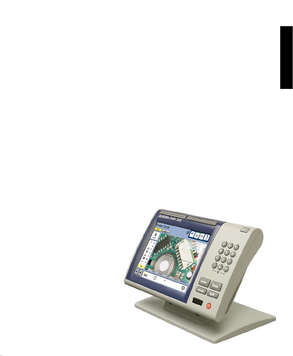
The Quadra-Chek 300 series is a family of advanced digital readout systems for performing 2, 3 and 4
axis measurements at very high levels of precision and accuracy. Dimensional inspection of components
can be made using toolmaker’s microscopes and video measurement systems as part of in-line production
activities or final quality inspection.
Feature points are entered manually using crosshairs or video edge detection, or automatically using the
multiple video edge detection probe. Feature type can automatically be determined by the system when
using Measure Magic. Part level and skew compensation can be performed on misaligned parts prior to
measurements that eliminates the need for time-consuming fixturing.
Sequences of key-presses used to perform measurements can be recorded and stored as programs. These
programs can be replayed later to perform complete measurement sequences. Sequences can be as simple
as measuring a line, or can be expanded to include skew adjustment, datuming, the measurement of multiple
features, tolerancing and printing reports of measurement results. Programs can include the CNC motion
control option to fully automate program execution, increase thoughput and simplify operator tasks.
1
Overview
The intuitive interface will be familiar to users of
the QC-200 and other Metronics digital readouts.
Operators will find the QC-300 easy to understand
and use thanks to the large color touch screen
LCD display.
The color LCD displays alphanumeric
and graphic information for the current
measurement, part features and measurement data clearly on one screen,
eliminating the need to page or scroll
for information.
Touch screen controls select the feature to
be measured, change operating and display
modes, zero axes, and configure setup parameters.
Touch screen controls change to support measurementspecific functions displayed on the LCD screen.
Page 22
2
QC-300 Series User’s Guide
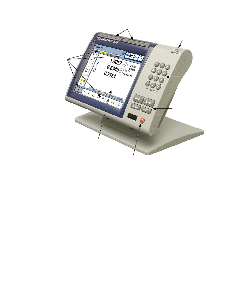
Wide keys
Print/Send data
Touch screen
controls
Numeric keypad
Command keys
Color touch
screen
LCD ON/OFF
Front panel keys enter numeric data, turn the LCD on or off and send data to a printer or computer. Two
wide keys located over the LCD can quickly be pressed without looking at the front panel to initiate
frequently used functions programmed by the user. All front panel keys provide tactile sensory feedback,
and key-press operations can be configured to generate an audible sound.
Speaker and external speaker jack outputs are provided that can be adjusted for quiet or noisy
environments. Ear phones can be plugged into the external speaker jack to facilitate silent operation in
quiet environments.
Page 23
Features
3
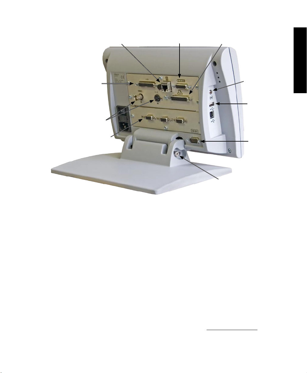
External footswitch
Lighting and zoom
Video inputs
Encoder inputs
CNC outputs
Not used
Tilt adjust
1
Overview
Speaker jack
USB port
RS-232 port
Video camera inputs are displayed on the color LCD and support NTSC and Pal formats as composite video
and S-video signals. Video images can be stored as JPEG snapshots using the optional image archiving
functions.
Measurements viewed on the LCD can be transmitted to a PC over USB or RS-232 ports or to a printer
over the USB port.
The compact ergonomic design and adjustable-tilt front panel of the QC-300 allow users to locate and
mount the instrument in a wide variety of environments that accommodate nearly any viewing requirement.
The tilt front panel can be adjusted and secured in any convenient position. Rubber feet on the bottom
prevent slipping when the system is not permanently bolted to a work surface using the bolt holes provided
in the mounting stand.
Optional foot switch is available for operation when the user is not close to the front panel. All the optional
accessories for the QC-300 are shown in detail at the rear of this guide in Chapter 14: Options.
Page 24

4
QC-300 Series User’s Guide
Page 25
Chapter 2:
Installation
The QC-300 is easy to install in a variety of basic and advanced measurement applications. This chapter
describes how to unpack and install the QC-300. Repackaging instructions are also included for return
shipments and for distributors and OEM customers that are configuring a QC-300 and shipping it to an
end-user.
Unpacking the QC-300
Carefully remove the contents of the shipping carton.
NOTE
Save the carton and packaging materials in case future reshipment becomes necessary.
5
2
Installation
Inspect the components listed below for shipping damage. The contents of the carton includes:
• QC-300 instrument • Mounting stand and hardware
• Power cord • Warranty registration card
Shipments of other optional equipment in separate cartons might include:
• RS-232 serial cable • Video cable
• Light control cable • CNC output cable
• Foot switch • Taltech’s WinWedge® software
If any components were damaged in shipment, save the packaging materials for inspection and contact
your shipping agent for mediation. Contact your Metronics distributor for replacement parts.
Page 26
6
QC-300 Series User’s Guide
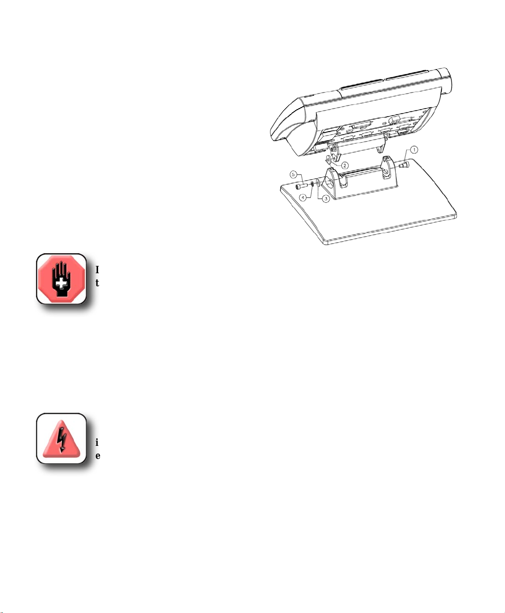
Assembling the mounting stand
The QC-300 is secured to the swivel slots of the mounting stand by a shoulder
screw, a cap screw and associated washers.
Assemble the QC-300 to the mounting stand as shown.
Tighten the shoulder screw (1), and then tighten the cap
screw (5) and washers (3 & 4) so that the QC-300 will
be secure when adjusted to the desired tilt position.
Safety considerations
The QC-300 is completely enclosed and no hazardous outputs can come in contact with the user. Safety considerations
are related to power connections and physical mounting.
WARNING
If the QC-300 falls from its mounting location, serious personal injury or damage to
the equipment can result.
Power cord and plug
Do not locate the power cord where it can be walked on or will create a tripping hazard. Connect the 3-wire
power plug to only a 3-wire grounded outlet. Never connect 2-wire to 3-wire adapters to the power cord
or remove the third ground wire to fit the plug into a 2-wire electrical outlet. Modifying or overriding the
third-wire ground creates a safety hazard and should not be permitted.
DANGEROUS VOLTAGE
Always disconnect the power cord from the source of AC power before unplugging
it from the QC-300 power connector. The AC voltage available at electrical outlets is
extremely dangerous and can cause serious injury or death.
Electrical wiring and connections
Perform regular inspections of all connections to the QC-300. Keep connections clean and tight. Locate
cables away from moving objects. Do not create tripping hazards with power cords, input/output cables or
other electrical wiring.
Use shielded cables to connect to the serial RS-232 port. Make certain that cables are properly terminated
and firmly connected on both ends.
Page 27
Safety, Power and Encoders
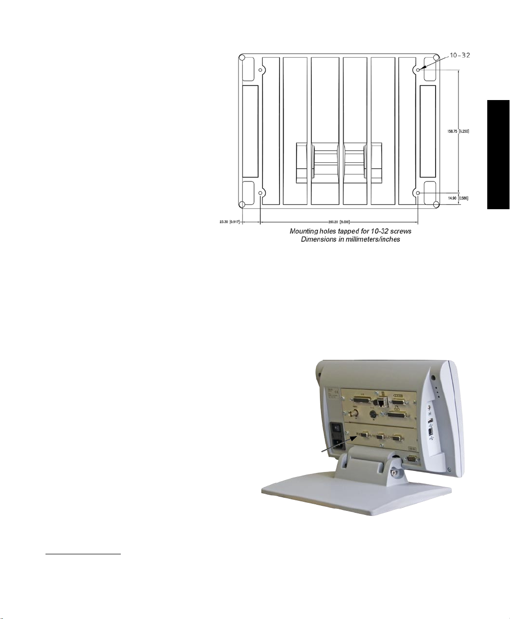
Location and mounting
Rest the QC-300 on a flat, stable surface,
or bolt it to a stable surface from the bottom using four 10/32 screws fastened in
the pattern shown at the right.
Power surge suppressor
Connect the QC-300 to power through a high-quality power surge suppressor. Surge suppressors limit the
amplitude of potentially damaging power line transients caused by electrical machinery or lightning. When
a surge suppressor is not used, power line transients can corrupt system memory or damage circuits.
7
2
Installation
Connecting axis encoders
Axis encoders are attached to interface connectors on the rear of
the QC-300. Many encoder interfaces are available to match
the wide variety of encoders that can be used with the QC-300.
The type of axis encoder connectors will vary depending on the
application. Encoder inputs are specified as analog or TTL at
the time of purchase and cannot be changed in the field.
1 Verify that the QC-300 is off.
2 Connect the axis encoders tightly to their
connectors. An axis label is provided near
each connector. Do not overtighten the connector
screws.
Encoder input parameters must be configured later using the Encoder setup screen. Please refer to
Chapter 11: Setup for details regarding encoder setup.
X, Y, Z and Q axis
input connectors
Page 28
8
QC-300 Series User’s Guide
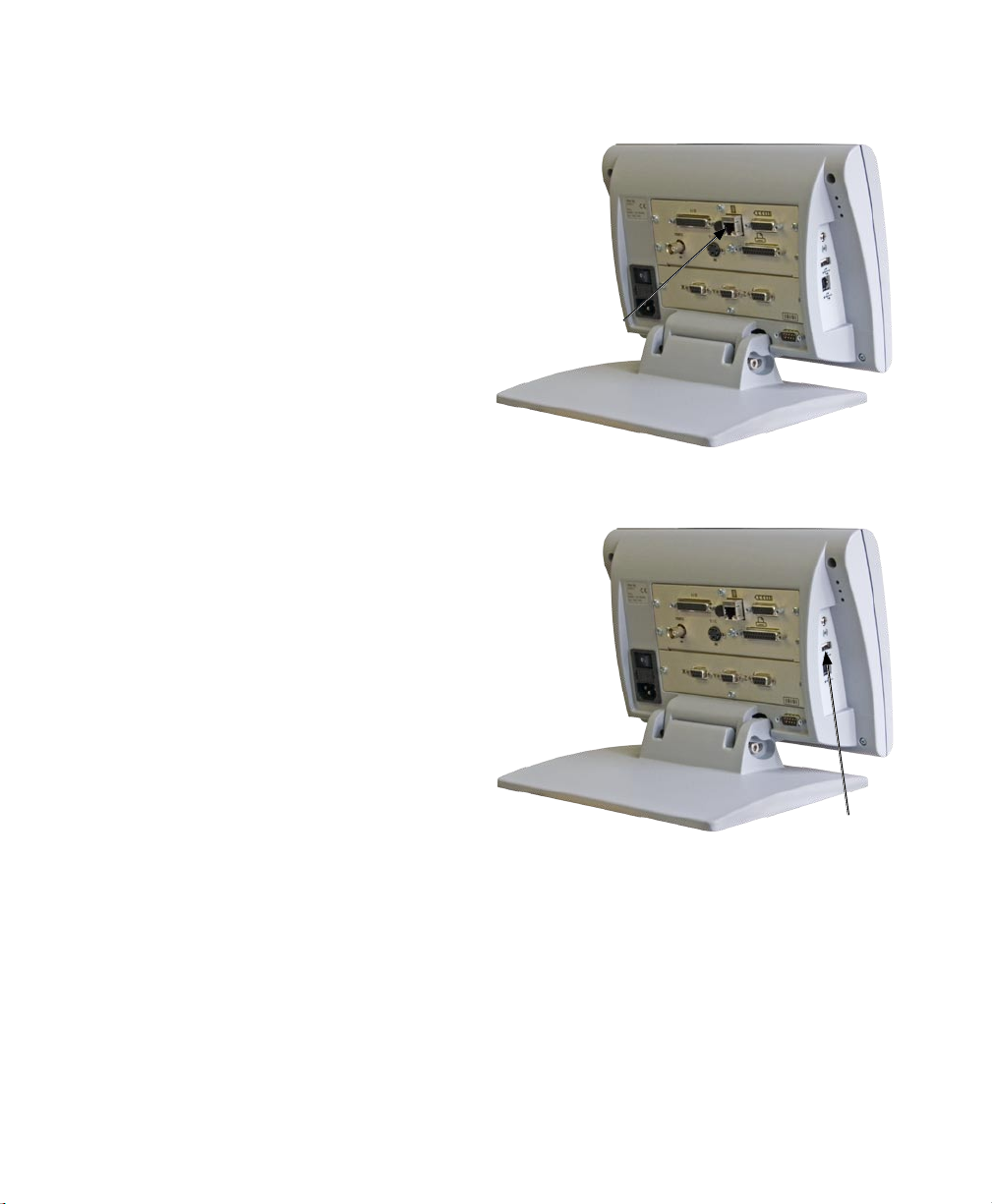
Connecting an optional footswitch
The optional foot switch is connected to the RJ-45 connector
on the left side of the QC-300.
1 Verify that the QC-300 is off.
2 Connect the foot switch to the RJ-45 connector on the rear
connector panel.
Footswitch connector
Connecting a printer
The QC-300 supports certain HP USB printers. Printer models
must be specified when the QC-300 is ordered, or approved by
Metronics later.
1 Verify that the QC-300 and printer power are off. Connect the
USB printer to the USB Type A port on the side of the enclosure.
2 Make sure the USB cable plug is fully inserted.
USB printer
port
Page 29
Connections
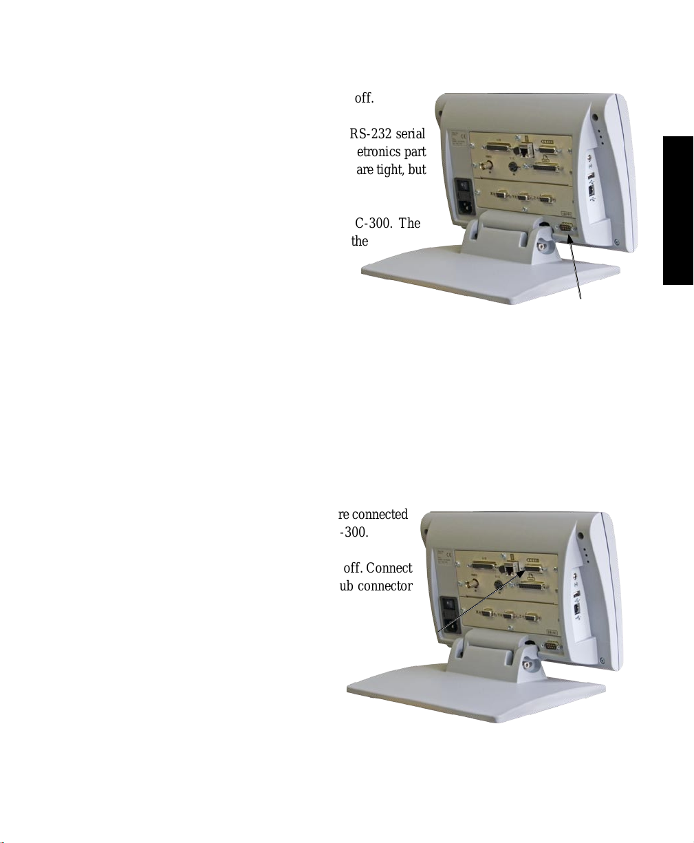
Connecting a computer
1 Verify that the QC-300 and computer power are off.
2 Connect a computer COM port to the QC-300 RS-232 serial
port using a standard straight-through serial cable (Metronics part
number 11B12176). Make sure the cable connectors are tight, but
do not overtighten the connector screws.
3 Apply power to the computer, and then the QC-300. The
default QC-300 settings for communication over the
RS-232 serial port are shown here.
9
2
Installation
• Baud rate: 1200
• Parity: None
• Data bits: 7
• Stop bits: 1
• Flow control: Hardware
4 Launch the computer application that will be used to communicate with the QC-300, and configure the
communication properties of the computer’s COM port and QC-300 to match.
RS-232 serial port
connector
Connecting optional CNC outputs
The optional CNC joystick and amplifier outputs are connected
at the CNC output connector on the rear of the QC-300.
1 Verify that the QC-300 and CNC amplifier are off. Connect
the CNC amplifier and joystick to the 26-pin D-sub connector
on the rear of the QC-300.
2 Make sure the connector is fully inserted and
make sure the cable connectors are tight, but do
not overtighten the connector screws.
CNC output
connector
Page 30
10
QC-300 Series User’s Guide
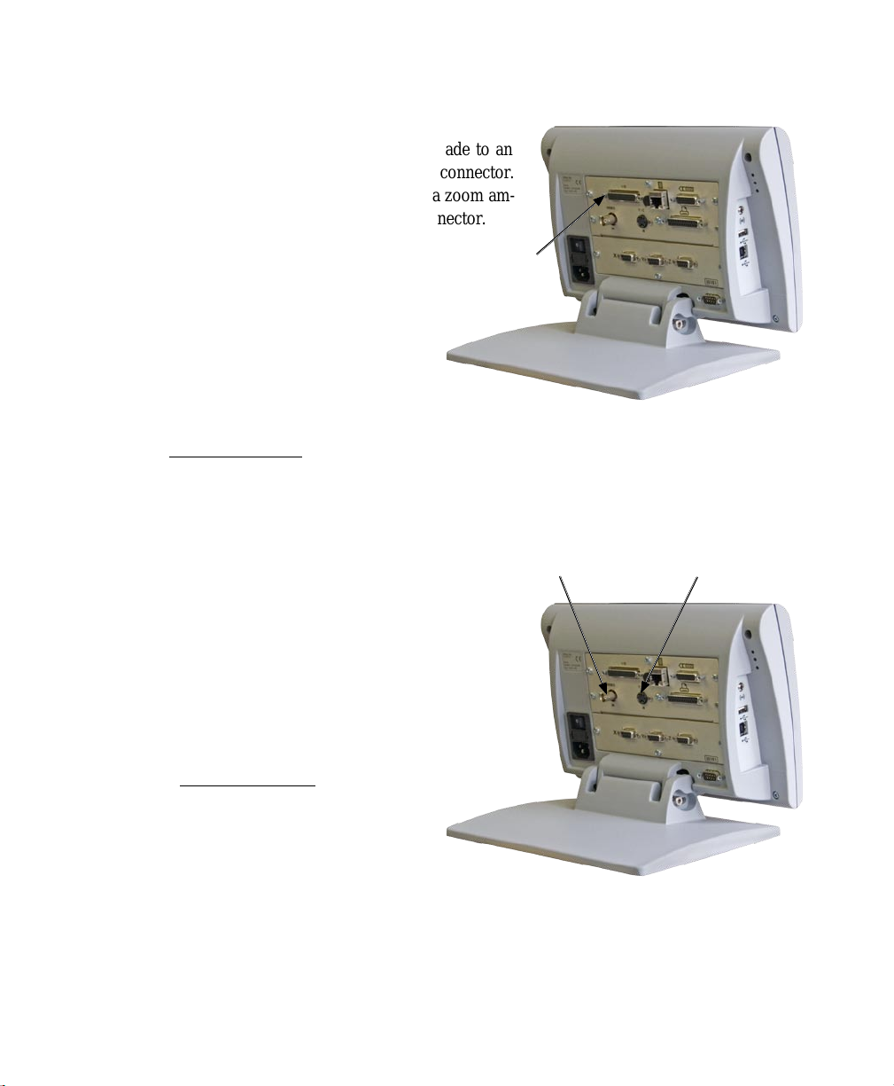
Connecting optional camera lighting and zoom
The QC-300 supports top, back and ring lighting for image
illumination. The lighting output connections are made to an
external light control box through the 44 pin D-sub connector.
The 0 to 5 Volt zoom control output connections to a zoom am-
plifier are also made through the Lighting/Zoom connector.
1 Verify that the QC-300, camera light control
box and zoom amplifier are off.
2 Tighten the lighting/zoom cable to the lighting/zoom connector on the back panel. Do not
overtighten the connector screws.
The lighting and zoom outputs must be configured using the Lighting and Magnifications setup screens.
Please refer to Chapter 11: Setup for details regarding lighting and zoom setup.
Camera lighting
and zoom
connector
Connecting a video input
The QC-300 supports composite and S-Video inputs for
NTSC and PAL systems.
1 Verify that the QC-300 and video camera are off.
2 Connect the video input to the composite or S-video connector. Make sure the connector is properly oriented and do not force
the connector into place.
The camera input must be configured later in the VED setup screen.
Please refer to Chapter 11: Setup for details regarding video
setup.
Composite video
connector
S-video connector
Page 31

Warranty and Shipping
Warranty registration form
The warranty registration form included in
the shipping carton should be completed and
mailed as soon as possible. Also record the
purchase and warranty information here so
that it will be readily available later to support
any necessary interactions with distributor or
factory technical support personnel.
The software version can be found in the
Hardware setup screen. Refer to Chapter 11: Setup for screen descriptions.
Repackaging for shipment
Repackage the QC-300 in the original packaging as received from the factory, or equivalent. It is not
necessary to ship the base when shipping the QC-300 for repair.
CAUTION
The original packaging must be duplicated and the LCD must be inserted face-up to
prevent damage to the LCD screen.
11
2
Installation
Pay special attention to the following instructions:
1 Connect any loose mounting hardware to the QC-300 instrument
2 Repackage the foam and cardboard carton inserts as originally shipped from the factory.
3 Place the QC-300 into shipping carton with the LCD facing up.
4 Replace the warranty card and slip sheets found at the top of the carton. The “Before you begin” slip
sheet should be inserted last.
What’s next?
Proceed to Chapter 11: Setup to configure your QC-300 for use. Follow the instructions for Essential Setup
as a minimum.
Page 32

12
QC-300 Series User’s Guide
Page 33

Chapter 3:
User Interface
The QC-300 user interface consists of hardware front panel buttons and number keys that work in cooperation with software menus, buttons, and data fields shown on the color LCD touch screen. The hardware/
software interface is divided into the function areas listed and shown below.
• Measurement functions • Contrast threshold adjustment
• Command buttons and wide keys • Number keys
• Feature list • System functions
• LCD Screen functions • Printing reports and sending data
• Auto-enter function • LCD ON/OFF or delete features
• DRO screen functions
13
3
User Interface
Feature
list
Command
wide keys
LCD Screen functions
Auto-enter
function
Measure functions
System functions
Printing reports
and sending data
Video
DRO panel
Number
keys
Contrast
threshold adj
Command
buttons
LCD
ON/OFF
Page 34

14
QC-300 Series User’s Guide
Measurement functions
The measurement functions are divided into as many as four tabbed areas:
• Measure Select a measurement type, such as circle or line
• Program Record, edit or play back a program of measurement steps
• Light Adjust lighting for measurements on video systems
• Archive Store JPEG stills of video images (optional on VED systems)
Selecting a measurement type
Measurement types are selected from the Measure tab. Touch the Measure tab to display icons for the
different measure types.
Touch the Measure tab... to display measure types
Touch a measure icon to select the desired measure type. In some cases, such as when selecting circles and
slots, related measure types will also be presented as shown in this example of touching the circle icon to
display the arc measure type.
Touching the circle measure icon... also provides access to the arc measure type
NOTE
Details regarding performing measurements and the use of measurement tools are
provided in Chapter 6: Measuring.
Page 35

Measurement and Programming Functions
Accessing programming functions
Programming functions are accessed from the Program tab. Touch the Program tab to display a list of
programs and programming tools.
Touch the Program tab... to display a list of programs and programming tools
Touch a program tool icon to play, record, edit, copy, stop or add a user message to a measurement program. Completed program steps are shown in the feature list.
15
3
User Interface
Programming tools shown before recording Programming tools shown during recording
Run a program Run a program
Record a program Stop recording
Open edit mode Open edit mode
Copy a program Include user message
Goto here: Used to define locations for
CNC program safe moves
NOTES
Details regarding programming and the use of programming tools are provided in
Chapter 8: Programming.
Additional CNC functions that can be included in programs are contained in the Extra
tab shown later in this chapter and described in Chapter 11: Setup, in the Display screen section.
Page 36

16
QC-300 Series User’s Guide
Accessing part lighting adjustment tools
Lighting adjustment tools are accessed from the Light tab. Touch the Light tab to display the lighting
adjustment tools.
Touch the Light tab... to display light adjustment tools
Touch an icon to select the desired light adjustment. Systems can be ordered with adjustments for backlights, surface lights and camera ring lights. Each area of lighting is adjusted by a slider that brightens or
attenuates the light intensity of the selected area from 0 to 100 % in steps of 1 %.
Touch the Light area icon... and adjust the light intensity slider
The system can be configured in the VED setup screen to include Image controls in addition to the light adjustments. Touch the Light/Image control tab repeatedly to toggle between the light and image controls.
Touch the Light tab... to display Image controls
NOTE
Details regarding the use of light adjustment and image control tools are provided in
Chapter 6: Measuring.
Page 37

Video archiving
Storing JPEG stills of video images
Video archiving is available as an option on systems that include video edge detection. Touch the Archive
tab to display the video archiving tools.
Touch the Archive tab... to display video archiving tools
Snapshots of video images are captured as JPEG stills and then can be edited to include text, geometric
shapes and file metadata.
17
3
User Interface
Touch the Camera icon... to capture a JPG snapshot of the video image
Selecting a captured image in the feature list causes additional icons to be displayed in support of text and
graphic editing functions.
NOTE
Details regarding the image archiving and editing functions are provided in
Chapter 9: Image Archiving.
Page 38

18
QC-300 Series User’s Guide
Sending data to a computer from the Extra tab
Touch a data icon shown in the Extra tab to send the corresponding data element for the current position or
selected feature to a computer over the serial port. Touch the Extra tab to display the data choices.
Touch the Extra tab... to display the data choice icons
NOTE
The Extra tab is configured in the Display setup screen. Please refer to
Chapter 11: Setup for details.
The data sent to the serial port always corresponds to the information displayed in the Video or DRO
screens. The information types are shown in the upper-right corner of the screen and are:
Current position (no feature selected) • Feature measurement (feature selected)
•
• Archived image (image file selected)
Send current position data... send feature measurement data... or send archived image data
Page 39

Sending Data from the Extra Tab
NOTES
Archived image data only includes the X, Y or Z position of the image.
Touching an icon for an inappropriate data type produces no result. For example,
touching the diameter icon when a circle feature is selected in the feature list sends
diameter data to the serial port, however, touching the angle icon when a circle is selected produces
no result.
The Extra tab is typically used to send abbreviated data to the serial port since complete reports or screens
of data can be sent using the Print function described in Chapter 10: Setup for the Print screen settings.
However, a complete data set can be sent for a feature by touching the required series of icons in succession.
19
3
User Interface
The complete data set for the selected circle is sent to a computer by touching each data icon in succession
The transmission of data to the serial port from the Extra tab can be included in programs, like any other
measurement, tolerancing or reporting activity.
Page 40

20
QC-300 Series User’s Guide
CNC and other Extra tab functions
Additional CNC functions for programming, motion control and Extra tab formatting functions can also be
made available in the Extra tab as described in Chapter 11: Setup, in the Display screen section.
Extra tab functions
Space menu insert
The space insert are included in the Extra tab to separate control functions into
groups on the tab.
Divider line menu insert
The divider line insert are included in the Extra
tab to separate control functions into groups on
the tab without using a space insert.
Data prompt function
The data prompt function is included in the Extra tab to send a user-defined measurement such as X
position, Y position, radius or angle to the serial port, USB printer or USB drive as a file. When the
user touches the data prompt function, a prompt message is displayed and the user selects the desired piece
of measurement data to be transmitted.
Extra tab divided by space into data and CNC groups
Extra tab divided by line into data and CNC groups
Laser pointer ON/OFF
The laser pointer ON/OFF function is included in the Extra tab to toggle the laser pointer on or off.
When the user touches the laser pointer ON/OFF function, the laser is toggled on or off.
Joystick motor speed
The Joystick motor speed function is included in the Extra tab of systems with the
CNC option to adjust the joystick control of motor speed. When the user touches
the Joystick motor speed function, the joystick control of motor speed is toggled
between fast and slow.
Axis lock
The Axis lock function is included in the Extra tab of systems with the
CNC option to restrict stage motion to only one axis. When axis lock is on,
motion is permitted only along one axis; diagonal motion is not permitted.
When the user touches the Axis lock function, axis lock is toggled on or off.
Fast Slow
Axis lock onAxis lock
off
Page 41

CNC and other Extra Tab Functions
Part following
The Part following function is included in the Extra tab of systems with the CNC option. Part following changes the motion
reference from the machine coordinate system to the part coordinate system after a part skew has been performed. For example, if a skew
is performed along the part’s X-axis, when part following is enabled, subsequent X-axis motion will follow
the part skew, not the machine coordinate’s X-axis. When the user touches the Part following function,
part following is toggled on or off.
Part following onPart following
off
21
Stop motion
The Stop motion function is included in the Extra tab of systems with the
CNC option to stop all stage motion. When the user touches the Stop motion function, motion is toggled on or off.
Goto feature
The Goto feature function is included in the Extra tab of systems with the CNC option. When the
user touches the Goto function, the stage is moved to position the probe over the feature currently
selected in the feature list.
Motion
stopped
Motion
enabled
Multiple Extra tabs
Multiple Extra tabs might be necessary to display all the Extra tab functions available. Touch the Extra tab
repeatedly to access multiple tabs.
Touch the Extra tab repeatedly to cycle through available tabs
3
User Interface
Page 42

22
QC-300 Series User’s Guide
Command buttons and wide keys
The command buttons and wide keys are primarily used to support measurement and setup activities.
The command wide keys are duplicates of the Enter and Finish functions which are the most frequently
used command buttons, and can be located and pressed easily by the operator without looking at the front
panel.
Enter function Finish function
Command
wide keys
Command
buttons
• Enter Enters a point (or points) into a measurement, or enters a value into a measurement
data field, tolerance data field, communication data field or a setup data field
• Finish Completes a measurement, tolerancing or setup session
• Cancel Removes the last point from a measurement, deletes a feature from the feature list,
or removes the last character from a data field
• Quit Cancels a measurement in progress, ends a setup session without saving new settings
and ends a programming session
NOTE
Details regarding the use of the command keys are provided in Chapter 6: Measuring,
and are distributed throughout the remainder of this user guide.
Page 43

Feature list
The feature list provides access to all features that have been measured, constructed
or created. Measurements are selected by
touching them in the feature list, and then
viewed or toleranced in other screens.
When the feature list contains too many
entries to be displayed simultaneously,
the arrow keys at the bottom of the list are
used to scroll up or down to display all the
entries.
Feature List
Feature
list
23
3
User Interface
Selected measurements can be... viewed... or toleranced in other screens
When recording, playing or editing programs, the program steps are
shown in the feature list.
NOTE
Details regarding the use of the feature list are
distributed throughout the remainder of this user
guide.
Page 44

24
LCD Screen Functions
LCD Screen functions
The LCD screen functions are used to select the
screen that will be presented on the color touch LCD,
generally in support of the next operator activity
Touch a button to select the desired screen.
• Video Displays the camera’s view
• DRO Displays the digital readout
• View Displays the selected feature’s data cloud
• TOL Displays the tolerance screens for entering and editing tolerances
LCD Screen functions
Video screen DRO screen View screen Tol screen
NOTE
Details regarding the use of the four basic screen types are distributed throughout the
remainder of this user guide.
Page 45

Number keys
The number keys are used to enter
data into feature constructions and
creations, tolerances, programs, and
setup data fields.
Numbers are entered into data fields
in the conventional manner, and can
be erased when necessary by backspacing over them using the Cancel
button.
NOTE
Details regarding the use of number keys are distributed throughout the remainder of
this user guide.
Number Keys
25
Number
keys
3
User Interface
Page 46

26
QC-300 Series User’s Guide
System functions
System functions support a wide variety of measurement and setup activities. System functions
include:
• Datum lock indication
• Undo
• Magnification (Mx)
• Unit of measure (mm/Inch)
• Setup
System functions
Datum lock indication
The lock icon indicates that features are locked to the datums used when they were measured. When the
lock icon is not shown, new datums are applied to all features in the feature list as they are created.
Undo
The Undo function is very similar to the Windows undo function and erases the last measurement or
feature list activity step. The Undo function only erases the last step, sequences of steps cannot be
erased using undo.
MX
The MX (shown here as M1) function provides access to a drop down list of available video magnifications. Touching the MX button shows the list of available magnifications. Touch the desired magnification to select it.
Touch the M1 button... to select a video magnication... from the drop-down list
Page 47

System Functions
mm/in
The mm/in function toggles the
linear unit of measure between
metric and English. Touch the
mm/in button to toggle the units
of measure.
Touch the mm/in button... to change the linear unit of measure
Setup
The setup function provides access to all of the system setup screens required for configuring QC-300
measurement and operation. Touch the setup button to display the setup screen and menu. Access to the
setup menu is given through two introductory screens that show the software version, the system options
and a caution regarding the use of setup functions.
27
3
User Interface
Setup screen tools will be made available to those who can provide a valid supervisor password.
NOTE
Detailed descriptions of all setup functions and tools are contained in
Chapter 11: Setup.
Page 48

28
QC-300 Series User’s Guide
Adjusting contrast threshold
Screen contrast is a combination of the illumination difference between adjacent light and dark
regions on the screen and the sharpness of the
transition from light to dark. Perfect contrast
could be loosely described as very light and very
dark regions that meet at a very sharp transition.
The contrast of an edge is shown by the height of
the gray bar as the video probe moves across an
edge. The contrast threshold required for edge
recognition is shown by the yellow arrow and
must fall within the gray bar. When the threshold adjustment is unlocked in the VED setup
screen, the contrast threshold can be increased
or decreased by raising or lowering the yellow
arrow on a contrast bar.
Adjust the contrast threshold by touching and sliding
Video DRO panel
A small digital readout panel is shown in the upper-right corner of the
video screens. Touching the panel cycles it to one of three possible
display modes:
the yellow arrow
• Current position display
The current position of each axis is shown numerically in the
current unit of measure.
• Minimized DRO icon
Icon indicating the availability and position off the DRO panel.
• Current positions for zeroing axes
Touching an axis value zeros the axis and creates a new measurement datum.
Current position Minimized DRO icon Current positions for... zeroing axis values
Page 49

Auto-enter Function
Auto-enter function
Feature data can be collected manually by positioning a probe over a part feature and pressing the Enter
key, or collected automatically by enabling the auto-enter function. In crosshair systems, a single point
is acquired each time the stage is moved to a new probing position. In video systems, automatic probing
can acquire many points simultaneously to greatly increase productivity when edge boundaries are clear
and distinct.
The auto-enter function is enabled or disabled by touching the auto-enter icon located in the upper-left corner
of the video screen.
When the auto-enter function is enabled, points will be acquired automatically after the stage motion stops
to position the probe over a feature
or edge. Refer to the descriptions of
crosshair and edge timeout delays in
Chapter 5 Probes.
When the auto-enter function is enabled, the icon dot rotates clockwise around the icon and changes color
to indicate the crosshair or edge timeout delay period prior to acquiring the point. This delay is restarted if
the stage is moved an amount equal to or
greater than the Motion Distance value
specified in the Tool Options portion of
the probe pop-up screen.
Disabled
Enabling the auto-enter function
The Auto-enter icon dot rotates clockwise from 3:00 to 12:00 in
Auto-enter
icon
Enabled
the delay before a point is automatically probed
29
3
User Interface
Printing reports and sending data
Measurement data shown on the DRO screen or contained
in the feature list can be printed in reports on the USB port
or sent to a computer over the RS232 serial port. In either
case, the printing of reports and the transmission of measurement data is initiated by pressing the Print button.
NOTE
Report printing and data transmission
are configured in the Print setup screen
described in Chapter 11: Setup. Printing and data transmission are described
in Chapter 10: Communication.
Page 50

30
QC-300 Series User’s Guide
DRO screen functions
Touching certain items displayed on the DRO screen allows the user to:
• Toggle between cartesian and polar coordinate systems
• Toggle between diameter and radius displays
• Select fit algorithms
Toggling between cartesian and polar coordinate systems
Touch one of the X, Y or the R, θ coordinate designation characters to toggle between coordinate systems.
Touch a coordinate designation character to toggle between cartesian and polar coordinates
Toggling between diameter and radius displays
Touch the D or R designation characters to toggle between diameter and radius.
Touch the D or R designation character to toggle between diameter and radius displays
Page 51

DRO Screen Functions
Selecting a fit algorithm
To change the fit algorithm used to determine form errors for the selected feature:
1 Touch the Fit designation
on the right side of the screen to
display the fit algorithm choices
for the displayed feature.
2 Touch the button icon that
corresponds to the desired fit algorithm. The new fit algorithm
will be applied.
31
3
User Interface
Page 52

32
QC-300 Series User’s Guide
LCD ON/OFF and deleting feature data
The LCD screen can be turned off without cycling power
when the QC-300 will not be used for an extended period,
but it is desirable to retain the original machine zero encoder references. Press the red LCD ON/OFF button to
toggle the LCD on and off.
When the LCD ON/OFF button is pressed, the operator is
given an opportunity to erase all feature measurement data
and resume operation without turning the LCD off. If the
operator presses the Enter key to delete feature data, the
system will ask for confirmation. If confirmation is given,
the feature data and datums will be permanently deleted.
You will be asked to press Enter... and asked to conrm the delete... then the feature data will be deleted
CAUTION
Delete feature data only when you have saved the data in a report, transmitted it to
a computer file or are sure that you no longer need them. Once the data are deleted,
they cannot be restored.
Page 53

Chapter 4:
Quick Start Demonstration
This chapter demonstrates the operation of the QC-300 system. The demonstration is provided as a means
of quickly helping experienced operators to use the system. This demonstration will be most helpful if you
perform the measurements and other activities as you follow along.
The demonstration will use the Metronics QC Quickie slide to create a part skew and datum, measure some
part features, apply a few tolerances, print a tolerance report and save all these activities as a program that
can be recalled and run again later.
33
4
Quick Start
Individual steps are
The QC Quickie slide is shipped with each system
When the program is run on manual or CNC systems,
the series of required points will be indicated by a green
arrow that moves over the part outline in the Part View
or Video window. For manual systems, the user need
only probe locations indicated by the arrow to complete
measurements. For CNC systems, the measurements are
performed automatically.
The demonstration will show measurements being performed on a video stage using a video edge detection
probe. However, the same measurements could also be performed on a microscope or comparator using
crosshairs.
Detailed information regarding datuming and measuring is contained in Chapter 6: Measuring. Information regarding tolerancing is contained in Chapter 7: Tolerancing. Report printing is discussed in Chapter
10: Communication. Information regarding programming is contained in Chapter 8: Programming.
Summary of the Quick Start Demonstration
recorded as a program
Page 54

34
Starting program recording
To record the following activities
as a program:
1 Touch the Program tab to display the program screen and then
touch the Record icon. The text
entry screen will be displayed.
2 Enter a program title and
press the Finish key. The DRO
or Video screen will be displayed.
Touch the Measure tab to begin
measurements.
Selecting a probe
To select a new probe:
QC-300 Series User’s Guide
1 Select a new probe type by
touching any part of the current
probe on the Video window. The
four probe choices will be shown
on the probe pop-up screen.
2 Touch the desired probe type
button. The probe pop-up screen
will close and the new probe will
be displayed. In this example
the straight crosshair probe is
selected.
NOTE
More information regarding preparing and using probes is contained in
Chapter 5: Probes.
Page 55

Selecting a Probe & Skew and Datum
Creating part skew and datum references
When the part is misaligned (twisted) in the X-Y plane, errors can be generated during the measurement
process. These errors can be eliminated by creating a skew alignment for the part.
The skew alignment includes a precise measurement of the part misalignment. Once the misalignment is
known to the system, subsequent feature measurements are automatically compensated to eliminate misalignment errors. Measurement data in the DRO will reflect measurements of a perfectly aligned part.
Creating a part skew
To skew the part:
1 Touch the Skew/Level Measure icon.
35
4
Quick Start
2 Perform the skew alignment by probing 2 or more points well distributed along the entire length of the
desired part reference edge. Press the Enter key to enter each point. Press the Finish key to complete the
Skew measurement. The skew line feature will be added to the Features list in blue.
Page 56

36
QC-300 Series User’s Guide
Creating a datum zero point
Creating the datum zero point is the final step in establishing a valid Cartesian or polar coordinate system
for subsequent measurements. The datum zero point will be used as the origin of Cartesian or polar systems. The datum zero point can be positioned in any location that satisfies the measurement requirements
of the user and can be created by probing a point or by constructing a point from parent features.
Probing a datum zero point
The datum zero point can sometimes be created directly by probing a point. Simple probing is more often
possible when the part is precisely aligned in the stage.
To probe a datum zero point:
Touch the Point Measure icon. Probe the desired point for the datum zero, and then press the Finish
1
key. In this example, the lower left corner of the QC Quickie slide was probed. The point will be added
to the Features list in blue.
2 Select the DRO window, and
while the point feature is selected
touch the X and Y axis Zero buttons to zero the values and establish a datum zero at the probed
point.
Page 57

Creating a Datum
Constructing a datum zero point
The datum zero point can be constructed from parent features when simply probing the desired point is
not desirable.
It would not be possible to provide a single description of this process for all measurement applications that
require feature constructions. However, the concept illustrated by the following example and the construction techniques described later in Chapter 6: Measuring can be used to construct a datum zero point for
any measurement application.
In this example, after the part skew is performed, and then a datum zero point is created at the intersection
of the X-axis along the bottom of the part (skew axis), and the Y-axis along the left side of the part.
To construct the datum zero point:
1 Touch the Measure Line icon. Probe two or more points well distributed along the left side of the part,
and then press the Finish button. The line feature will be added to the Features list.
37
4
Quick Start
3 Touch the Measure Point icon, touch the skew line, touch the line probed on the left side of the part
and then press the Enter key. A point constructed at the intersection of the two lines will be added to the
Features list.
Page 58

38
4 Select the DRO window, and
while the point feature is selected
touch the X and Y axis Zero buttons to zero the values and establish a datum zero at the probed
point.
NOTE
More information regarding creating datums and constructions is contained in
Chapter 6: Measuring.
QC-300 Series User’s Guide
Page 59

Measuring Features
Measuring features
In this example, the largest of the three holes of the QC Quickie slide will be measured twice illustrating
the use of two different probes. First the straight crosshair probe will be used, then the multiple edge probe
will be used.
Measuring a circle with crosshairs
To measure using crosshairs:
1 Select the straight crosshair probe.
Touch any part of a probe... to display the probe tools... and select a new probe
39
4
Quick Start
2 Touch the measure circle
icon and probe a minimum of
three points evenly distributed
around the perimeter of the circle.
Eight points were probed in this
example.
3 Press the Finish key to complete the feature measurement
and store the feature in the feature list. The feature and probed
points can be reviewed in detail
by touching the DRO or View
button if desired.
Select the circle measurement...
probe points around the circle and
press Finish to complete
Page 60
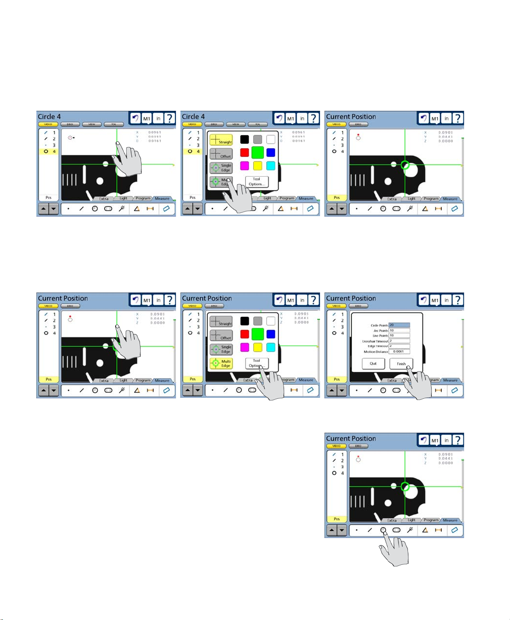
40
QC-300 Series User’s Guide
Measuring a circle with the multiple edge probe
To measure using the multiple edge probe:
1 Select the multiple edge probe.
Touch any part of a probe...
2 Touch the probe again to display the probe tools screen, and then touch the Tool Options button to
display probing parameters, set the number of circle points to 20 (or any number between 3 and 99), and
touch the Finish button.
Touch any part of a probe...
3 Touch the probe circle icon to begin the measurement.
to display the probe tools...
then touch Tools Options ... and set the number of circle points
and select the multi edge probe
Page 61

Measuring Features
4 Move the stage to position the multiple edge tool into the center of the large circle in the QC Quickie
slide and press the Enter key. The measurement will be completed and the circle data will be stored in the
feature list.
41
Move the stage to position...
The feature and probed points can
be reviewed in detail by touching
the DRO or View button if desired.
NOTE
More information regarding the use of the multiple edge probe is contained in
Chapter 5: Probes. More information regarding performing measurements is
contained in Chapter 6: Measuring.
the probe inside the circle... and press Enter to complete
4
Quick Start
Page 62

42
QC-300 Series User’s Guide
Applying tolerances to feature measurements
In this example, a true position tolerance will be applied to at the last circle measurement. To apply a
tolerance:
Select the feature
Touch the circle feature in the feature list to select it.
Display the tolerance screen
Touch the Tol screen button to
display the tolerance screen.
Select a tolerance type
Touch the desired tolerance type
button to select a tolerance type.
In this example, the position tolerance type is selected.
Page 63

Applying Tolerances
Select a specific tolerance
Touch the Tolerance menu title and then select the specific tolerance from the drop-down menu. The true
position tolerance is selected in this example.
43
Enter nominal, limit or tolerance values
In this example, the Nominal and Tol Dia (Tolerance diameter around the nominal position) values are
entered by touching the desired data field and entering a new value using the number keys. Error and
Deviation values are generated as soon as the Nominal and Tol Dia values are entered.
The Nominal, limit and Tol Dia values are entered...
Pass/fail results are indicated by green and red colors in the tolerance screen and in
the feature list. Pass is indicated by green, fail is indicated by red in the tolerance
screen. Any tolerance failure will be indicated by a red mark next to the feature in
the feature list. A green mark will be displayed in the feature list when all tolerance
tests pass.
NOTE
More information regarding tolerances is contained in
Chapter 7: Tolerancing.
resulting in new error and deviation values
4
Quick Start
Pass indication is a
green square
Page 64

44
QC-300 Series User’s Guide
Printing a report
To print a report of the current position (Display), the feature list (Report) or tolerances (Tol Report):
1 Verify that the QC-300 is attached to a USB printer as described
in Chapter 10: Communication.
2 Verify that the report content and printer formatting are
specified correctly in the Print setup screen described in
Chapter 10: Communication and Chapter 11: Setup.
3 Press the Print key while displaying the Current
Position in the Video or DRO screen.
NOTE
More information regarding reports of feature measurement data and QC-300 system
settings are contained in Chapter 10: Communication.
Page 65

Printing Reports & Saving Programs
Stopping the program recording
Touch the Program tab to display the programming tools, and then
touch the Stop icon to stop recording the program. The program title will be shown and program steps will be displayed in
the feature list.
The program is now saved and
can be edited or run on new parts.
Touch the Measure tab to leave
the record mode and return to the
measure mode of operation.
45
4
Quick Start
Running the program
To run a program, Touch the Program tab to display the program screen and then touch a program title to
select the desired program.
Touch the Run icon to run the
selected program.
Page 66

46
QC-300 Series User’s Guide
Page 67

47
Chapter 5:
Probes
Measurements are conducted using manual crosshairs, video crosshairs or video edge detection on manual
and CNC systems. Part features can be probed manually by the user or automatically under program
control.
Video probe setup and calibration is described in Chapter 11: Setup. The measurement, construction and
creation of features is explained in Chapter 6: Measuring.
Preparing to use video probes ..........................................................................48
System and part condition .........................................................................48
Selecting video magnification ...................................................................48
Adjusting light control ..............................................................................48
Adjusting video image contrast and brightness ........................................51
Using video probes ...........................................................................................54
Selecting a probe ......................................................................................54
Selecting a probe color ..............................................................................55
Specifying probe data collection parameters ............................................56
Crosshair probe data collection parameters .......................................57
Edge probe data collection parameters ..............................................58
Collecting feature data ..............................................................................59
The auto-enter function ......................................................................59
Crosshair probes ................................................................................60
Manual probing (crosshairs) .......................................................60
Automatic probing (crosshairs) ..................................................61
Single edge probe ..............................................................................62
Manual probing (single edge) .....................................................62
Automatic probing (single edge) ................................................63
Multiple edge probe ...........................................................................64
Probe seeding ..............................................................................64
Probing a line ..............................................................................65
Probing a circle ...........................................................................66
Probing an arc .............................................................................68
Seeding to avoid erroneous data .................................................69
Recovering from data errors .......................................................70
5
Probes
Page 68

48
QC-300 Series User’s Guide
Preparing to use video probes
The accuracy and repeatability of video probing depends on the condition of the system, the condition of
the part, video magnification, part lighting and optical focus.
System and part condition
The system is presumed to be well-maintained which implies a clean stage and optical system, free of
scratches and other damage. The part to be measured is also presumed to be clean and undamaged.
Selecting video magnification
Select a different video magnification by adjusting the camera optics, touching the magnification button
and then touching the desired magnification in the drop-down menu. The magnifications that appear in the
drop-down menu are added and calibrated in the Magnifications setup screen by supervisors, distributors
and OEMs.
Adjusting light control
The video back light, surface light and ring lights are adjusted to optimize part illumination by selecting the
desired light sources and operating the light slider controls. Light sources can be different in each system
and can include:
• Back light Single light source directly under the part that provides back lighting
• Top light Single light source directly over the part that provides surface lighting, sometimes
through the lens
• Ring lights Four light sources are enabled or disabled individually and distributed in a ring
around the camera axis. The light intensities of all enabled ring lights are controlled
simultaneously as a single group. The ring lighting is often provided by one source.
To adjust the light sources:
1 Touch the Light/Image tab at the bottom of the screen repeatedly to display the Light controls.
Page 69

Preparing to Use Probes
When the Light tab is shown in the background...
Touch the Light tab... to display the light controls
When the Image tab is shown in the background...
49
5
Probes
Touch the Image tab...
2 Touch the desired light source to select it for adjustment.
Select the back light... Select the top light... or ring lights
twice... to display the light controls
Page 70

50
When ring lights are selected,
touch the ring light icon again to
display individual ring right segments.
Any of the individual ring light segments can be turned on or off by touching them.
All ring light segments are off Two ring light segments are on All ring light segments are on
Touch the ring light icon again to display the adjustment slider.
QC-300 Series User’s Guide
Touch the ring light icon again... to show individual segments
3 Touch and drag an adjustment slider to adjust the illumination of any light source. All light sources
are adjusted in this manner using its own slider.
Touch and drag the slider... to make light adjustments
Page 71

Preparing to Use Probes
51
Adjusting video image contrast and brightness
The contrast and brightness of the video camera image displayed in the video window are adjusted to
optimize edge detection by selecting the Image tab and using the image contract and brightness sliders.
NOTE
The video image contrast and brightness adjustments are different than the overall
screen brightness adjustment found in the Miscellaneous setup screen.
To adjust the video image contrast and brightness:
1 Touch the Light/Image tab at the bottom of the screen repeatedly if necessary to display the Image
controls.
When the Image tab is shown in the background...
5
Probes
Touch the Image tab... to display the Image controls
When the Light tab is shown in the background...
Touch the Light tab...
twice... to display the Image controls
Page 72

52
2 Touch the contrast icon and then touch and drag the contrast slider to adjust video contrast.
QC-300 Series User’s Guide
Touch the Contrast icon...
Drag left to decrease contrast... and right to increase contrast
3 Touch the Brightness icon and then touch and drag the brightness slider to adjust video brightness.
then touch and drag the slider... to adjust contrast
Touch the Brightness icon...
then touch and drag the slider... to adjust brightness
Page 73

Preparing to Use Probes
Drag left to decrease brightness... and right to increase brightness
NOTE
Contrast and
brightness can be
fine-adjusted by
one unit of contrast or brightness by touching
the slider bar on either side of
the slider control.
53
5
Probes
Touch left to adjust down 1 unit Touch right to adjust up 1 unit
Adjusting video image contrast threshold
The contrast of an edge is shown by the height
of the gray bar on the right side of the screen
when the crosshair probe is positioned over
an edge. The contrast threshold required for
edge recognition is shown by the yellow arrow and must fall within the gray bar. When
the threshold adjustment is unlocked in the
VED setup screen, the contrast threshold is
increased or decreased by raising or lowering
the yellow arrow on a contrast bar.
Adjust the contrast threshold by touching and sliding
the yellow arrow
Page 74

54
QC-300 Series User’s Guide
Using video probes
Four video probes are available for creating reference levels, skews and datums and for measuring regular
geometric features including points, lines, arcs, circles, slots, rectangles, distances and angles. Probes
include:
• Crosshair Standard crosshair of two lines crossed at 90 degrees. Single points can be
acquired manually or automatically.
• Offset crosshair Crosshair of two lines with a regular pattern 3 pixel square wave offsets,
crossed at 90 degrees. Single points can be acquired manually or automatically.
• Single edge Standard crosshair with a small circle at the center for positioning the edge
detector. Single points can be acquired manually or automatically.
• Multiple edge Standard crosshair with 2 small concentric circles at the center for positioning
the edge detector. Multiple points can be acquired for certain feature types
automatically.
Crosshair
Firing a video probe generates one or more orthogonal scan lines, which acquire points as the scans cross
an edge bounded by light and dark areas of the screen image. The use of these four probes is very straightforward, as shown below.
Offset crosshair Single edge Multiple edge
Selecting a probe
To select a new probe:
1 Select a new probe type by
touching any part of the current
probe on the Video window. The
four probe choices will be shown
on the probe pop-up screen.
Page 75

Using Video Probes
2 Touch the desired probe type
button. The probe pop-up screen
will close and the new probe will
be displayed. In this example the
Multi-edge probe is selected.
55
Selecting a probe color
The probe color can be selected at any time from one of nine colors that are shown on the probe pop-up
screen. To select the probe color:
1 Touch any part of the current
probe on the Video window. The
nine color choices will be shown
on the probe pop-up screen.
5
Probes
2 Touch the desired probe
color button. The probe pop-up
screen will close and the new
probe color will be displayed. In
this example the red probe color
is selected.
NOTE
The color of the single edge and multiple edge probe circles (at the center of the probes)
cannot be changed because color is used to indicate whether or not an edge has been
detected. Red circles indicate that no edge has been detected. Green circles indicate
that an edge has been detected. The color of the remaining straight line portions of
edge probes can be changed.
Page 76

56
QC-300 Series User’s Guide
Specifying probe data collection parameters
Video probe data collection parameters are specified in the Tool Options portion of the probe pop-up
screen and include:
• The number of points to be collected for line, circle and arc measurement by the multiple edge probe
• Delays after the stage motion stops for auto-point entry using crosshair and edge probes
• The minimum stage motion required to restart the crosshair timeout delay for auto-point entry
using crosshair probes
• The line thickness of the crosshair probe
Usually, the data collection parameters are specified for a probe and remain unchanged until significant
changes are encountered in the part probing process, or the system hardware is changed.
To specify probe data collection parameters:
1 Touch any part of the current
probe on the Video window. The
probe pop-up screen will be displayed.
2 Touch the Tool Option button. The probe data collection
parameter setup fields will be
displayed.
Only a few data collection parameters are required, and they
are different for crosshair and
edge probes.
Page 77

Specifying Collection Parameters
Crosshair probe data collection parameters
Data collection parameters for crosshair probes include:
• Crosshair timeout delay
• Motion distance
• Line thickness
Crosshair timeout delay
When the auto-enter function is enabled during feature measurement on the LCD Video screen, a point is collected by the system each time the stage is moved to position the part under the
crosshair. This automatic point entry is delayed until the stage
has been motionless for a short time to ensure that the crosshair
is located where the user intended. This delay is the Crosshair
Timeout. This parameter is identical for the straight and offset
crosshair probes. The default value will provide adequate delay
for most applications, but can be increased to accommodate more relaxed probing.
The auto-enter function is enabled on
the LCD video screen
57
To specify Crosshair Timeout, touch the Crosshair Timeout data field and enter the desired delay in seconds using the number keys.
Motion distance
As described above, when the auto-enter function is enabled, a point is collected by the system each time
the stage is moved to position the part under the crosshair at a new location. This automatic point entry is
delayed until the stage has been motionless for a short time to ensure that the crosshair is located where the
user intended. This delay is restarted if the stage moves again during the timeout interval to facilitate final
fine adjustments of stage position.
To specify the minimum stage movement required to restart the crosshair timeout delay, touch the Motion Distance data field and enter the desired stage
motion in the current unit of measure (millimeters
or inches).
Line thickness
The lines of the crosshair probes can be changed in one-pixel increments from 1 to 3 pixels. To specify
the line width of the crosshair probe, touch
the Crosshair Thickness data field and enter
1, 2 or 3 pixels.
5
Probes
Page 78

58
Edge probe data collection parameters
Data collection parameters for edge probes include:
• The number of points to be collected for lines, circles and arcs by the multiple edge probe
• Edge timeout delay
Number of points probed for a line, circle and arc
When the multiple edge probe is used, the probe is seeded with a small number of points to define the
feature type, and then the remaining points are collected automatically by the system. Up to 99 points can
be collected for line, circle and arc features.
To specify the number of points collected for line, circle or
arc features, touch the Line, Circle or Arc Point data field
and enter the desired number of points using the number
keys.
Edge timeout delay
When the auto-enter function is enabled for feature measurement
on the LCD Video screen, a point is collected by the system each
time the stage is moved to position the part under the edge probe.
This automatic point entry is delayed until the stage has been motionless for a short time to ensure that the edge probe is located
where the user intended. This delay is the Edge Timeout. This
parameter is identical for the single and multiple edge probes.
The default value will provide adequate delay for most applications, but can be increased to accommodate more relaxed probing.
QC-300 Series User’s Guide
The auto-enter function is enabled on
the LCD video screen
To specify Edge Timeout, touch the Edge Timeout
data field and enter the desired delay in seconds using the number keys.
Page 79

Specifying Collection Parameters
59
Collecting feature data
Feature data can be collected manually by positioning a probe over a part feature and pressing the Enter
key, or collected automatically by enabling the auto-enter function and using the multiple edge probe.
Manual probing with crosshairs is useful when part edges are indistinct and feature edge contrast is poor.
Automatic probing can acquire many points simultaneously and increases productivity when feature edge
boundaries are clear and automatic point entry is possible.
The auto-enter function
The auto-enter function is toggled on or off by touching the auto-enter
icon in the upper-left corner of the video screen.
When the auto-enter function is toggled on, the crosshair and edge probes
will acquire a point automatically after the stage motion stops to position
the probe over a feature or edge. Refer to the descriptions of crosshair and
edge timeout delay on the previous two pages for more details regarding point acquisition timing.
When the auto-enter function begins
to acquire a point, the icon dot rotates
clockwise around the icon to indicate the
passage of the crosshair or edge timeout delay period. This delay is restarted if the stage is moved an
amount equal to or greater than the Motion Distance value described earlier.
OFF
The auto-enter function is
toggled on
ON
5
Probes
Page 80

60
Crosshair probes
The crosshair probes consist of two lines crossed at 90 degrees
in the video window. Probing is identical for straight and
offset crosshairs. Single points can be acquired manually or
automatically.
QC-300 Series User’s Guide
Manual probing (crosshairs)
Disable auto-enter for manual probing.
To probe part features manually:
1 Select the feature to be measured.
The Circle measurement is selected in
this example.
2 Position the probe over the desired feature location.
3 Press the Enter key to acquire a point.
4 Repeat steps 2 and 3 until all the required points have
been probed.
5 Press the Finish key to complete the feature measurement and store the feature in the feature list. The feature and probed points can be reviewed in detail by
touching the View button if desired.
Straight crosshairs
Offset crosshairs
Page 81

Probing
Automatic probing (crosshairs)
The process of probing automatically with crosshairs is identical to probing manually with crosshairs
except that the user does not press the Enter key to enter points.
Enable auto-enter for manual probing.
To probe part features automatically:
1 Select the feature to be measured.
The Circle measurement is selected in
this example.
2 Position the probe over the desired feature location.
3 The point will be acquired after the crosshair timeout delay, unless the stage is moved before the delay is complete. If
the stage is moved, the delay will be reinitiated.
61
4 Repeat steps 2 and 3 until all the required points have
been probed.
5 Press the Finish key to complete the feature measurement and store the feature in the feature list. The feature and probed points can be reviewed in detail by
touching the View button if desired.
5
Probes
Page 82

62
Single edge probe
The single edge probe consists of a standard crosshair
with a small circle at the center for positioning the edge
detector. Single points can be acquired manually or automatically.
Manual probing (single edge)
Disable auto-enter for manual probing.
To probe part features manually:
1 Select the feature to be measured. The Circle measurement is
selected in this example.
2 Position the probe over the desired feature edge. A blue
cross with indicate the point that will be acquired. Reposition the probe if necessary to acquire the desired point.
3 Press the Enter key to acquire a point.
QC-300 Series User’s Guide
Single edge probe
4 Repeat steps 2 and 3 until all the required points have
been probed.
5 Press the Finish key to complete the feature measurement and store the feature in the feature list. The
feature and probed points can be reviewed in detail by touching the View button if desired.
Page 83

Probing
Automatic probing (single edge)
The process of probing automatically with the single edge probe is identical to probing manually with
the single edge probe except that the user does not press the Enter key to enter
points.
Enable auto-enter for manual probing.
To probe part features automatically:
1 Select the feature to be measured. The Circle measurement is
selected in this example.
2 Position the probe over the desired feature edge. A blue
cross with indicate the point that will be acquired. Reposition the probe if necessary to acquire the desired point.
3 The point will be acquired after the edge timeout delay.
4 Repeat steps 2 and 3 until all the required points have
been probed.
63
5
Probes
5 Press the Finish key to complete the feature measurement and store the feature in the feature list. The
feature and probed points can be reviewed in detail by touching the View button if desired.
Page 84

64
Multiple edge probe
The multiple edge probe consists of a standard crosshair with two small concentric circles at the center for positioning the edge detector. Points will be probed
manually for some features as they are when the single edge probe is used, and
automatically for line, circle and arc features when the probe is seeded.
Probe seeding
When points are probed automatically as diagrammed at the right, the probe
must first be seeded by probing the minimum number of points required for
a geometric definition of the feature type. Only lines, circles and arcs can be
probed automatically.
• Line Points probed automatically after seeding with 2 points
• Circle Points probed automatically after seeding with 3 points
• Arc Points probed automatically after seeding with 3 points
• Point Points probed manually - identical to single edge probe
• Distance Points probed manually - identical to single edge probe
• Angle Points probed manually - identical to single edge probe
• Slot Points probed manually - identical to single edge probe
• Rectangle Points probed manually - identical to single edge probe
QC-300 Series User’s Guide
When probing lines, circles and arcs, the multiple edge probe must be seeded to
provide the system with a general description of the feature location. The location
of seed points is important. The order of seed points is important for arcs.
• Line Seed by probing 2 points at the extreme ends of the line.
• Circle Seed by probing 3 points evenly distributed around the perimeter
of the circle.
• Arc Seed by probing 3 evenly distributed points in sequence from
the beginning to end of the arc.
The seed points can be entered manually by
pressing the Enter key, or automatically using
the auto-enter function.
When all the required points have been seeded, a green arrow and red circle are
displayed. Move the stage to place the green arrow into the red circle to initiate
automatic probing of the remaining points and complete the measurement.
When the probe is seeded... move the stage to place... the arrow in the circle
Auto-enter
disabled
Auto-enter
enabled
Page 85

Probing
Probing a line
The same basic technique is used to probe a line whether the line is completely within or outside the field
of view. To probe a line using the multiple edge probe:
1 Select the Line feature measurement, and then select the multiple edge probe.
2 Seed the multiple edge
probe at the two extreme ends
of the line. The green arrow
and red circle will be presented.
Seed the multiple edge probe at the two extreme ends of the line
3 Move the stage to place the
green arrow inside the red circle.
The remaining line points will be
probed at roughly regular intervals along the line, the measurement will be completed and the
feature data will be stored in the
feature list.
Move the stage to place the arrow in the circle
65
5
Probes
4 The feature and probed points can be reviewed in detail by touching the View button if desired.
Page 86

66
Probing a circle
Two techniques can be used to probe a circle using the Multiple edge probe. The first technique is that
described earlier for probing lines and arcs and can be used to probe a circle whether the circle is completely within or outside the field of view. To probe a circle using the first technique with the multiple
edge probe:
1 Select the Circle feature
measurement, and then select
the multiple edge probe.
2 Seed the multiple edge
probe at 3 points evenly distributed around the perimeter
of the circle.
3 Move the stage to place the green arrow inside the
red circle. The remaining circle points will be probed
at roughly regular intervals around the perimeter of the
circle, the measurement will be completed and the feature data will be stored in the feature list.
QC-300 Series User’s Guide
Seed the multiple edge probe at 3 points evenly distributed around the circle
Move the stage to place the arrow in the circle
4 The feature and probed points can be reviewed in detail by touching the View button if desired.
Page 87

Probing
The second technique can only probe a circle located within the field of view that is large enough to enclose
the center of the Multiple edge probe, but the technique is extremely simple and productive. To probe a
circle using the second technique with the multiple edge probe:
1 Select the Circle feature measurement, and then select the multiple edge probe. Select a circle that will
completely enclose the center of the Multiple edge probe.
2 Move the stage to place the center of the Multiple edge probe
inside the circle. The center of the Multiple edge probe should be red
to indicate that no edge is detected.
3 Press the Enter key. All the circle points will be probed at roughly
regular intervals around the perimeter of the circle, the measurement
will be completed and the feature data will be stored in the feature
list.
67
5
Probes
4 The feature and probed points can be reviewed in detail by touching the View button if desired.
Page 88

68
Probing an arc
The same basic technique is used to probe an arc whether the arc is completely within or outside the field
of view. To probe an arc using the multiple edge probe:
1 Select the Arc feature measurement, and then select the multiple edge probe.
2 Seed the multiple edge
probe at 3 points in sequence
from the beginning to the end
of the arc.
QC-300 Series User’s Guide
Seed the multiple edge probe at 3 points in sequence from the beginning
3 Move the stage to place the green arrow inside the
red circle. The remaining line points will be probed at
roughly regular intervals along the length of the arc, the
measurement will be completed and the feature data will
be stored in the feature list.
4 The feature and probed points can be reviewed in detail by touching the View button if desired.
to the end of the arc
Move the stage to place the arrow in the circle
Page 89

Probing
Seeding to avoid erroneous data
The multiple edge probe can be seeded manually using the single edge probe to avoid collecting data over
keyways, protrusions and other feature anomalies. This is accomplished by:
1 Seeding points very close to, and enclosing the area of anomaly using the single edge probe
2 Switching to the multiple edge probe to complete the measurement by probing the reminder
of specified points automatically
Normally, the multiple edge probe attempts to collect the specified number
of points from an even distribution of probed points along the feature edge,
which includes the seed points.
As shown in the example below, when a line without anomalies is probed, the
multiple edge probe is seeded with the two endpoints, and then automatically
probes the remainder of the specified points at locations distributed evenly
between the endpoints.
16 Points are specied
for a line
69
5
Probes
The multiple edge probe is seeded with the endpoints of the line, and evenly distributes the remaining points
This process works well when the feature probed includes few or no edge anomalies. However, discontinuous or indistinct edges can lead to data errors if no preventive action is taken.
Since a combination of seeded locations and system-generated locations are used to distribute and probe
points, tightly enclosing any edge anomaly between two seeded points greatly reduces the possibility that
the multiple edge probe will probe the anomaly.
The single edge probe seeds the endpoints of the line and then probes additional seed points that enclose the
line anomaly. The multiple edge probe is then selected and the remaining points are probed automatically.
Page 90

70
Recovering from data errors
Data errors are rare when the part, stage and optical system are clean and well maintained, and the lighting,
contrast and brightness are properly adjusted. In addition, the QC-300 is extremely forgiving of typical
cleanliness and lighting issues. However, it is possible that an occasional data error will occur while the
Multiple edge probe is attempting to collect data from feature locations calculated from the seed points and
the specified number of total data points.
When a data error occurs, the system switches from automatic probing using the multiple edge probe to
manual probing using the single edge probe, and prompts the operator to either complete the measurement
with the available points, or to probe the remaining points manually. When the operator elects to continue
probing, he or she is guided to the required points by the green arrow. In either case the operator must press
the Finish key to complete the measurement.
While it is not expected that measurements would be conducted on a dirty stage like the one shown in this
example of a circle measurement, this dirty stage was used to produce a data error and illustrate the error
recovery process.
QC-300 Series User’s Guide
The Multiple edge probe seeds three points and user is prompted to move the green arrow into the red circle
When the seed points are probed the red target circle is displayed and the stage is positioned to place the green arrow
in the target circle. The system begins to probe the remaining points automatically, however, the stage is dirty and
makes the feature edge indistinct producing a data error.
The operator is then asked to complete the measurement
using the existing points or probe the remaining points
manually using the single edge probe.
Page 91

Probing
When the operator elects to continue probing the remaining points, the green arrow points to each missing
point which is signified by a large X. When the stage is moved to position the single edge probe and arrow
at the X and the Enter button is pressed, the next missing point is shown and the green arrow points to it.
When all the remaining missing points are entered, the Finish key is pressed to complete the measurement
and store the feature data in the Feature list.
The Multiple edge probe seeds three points and user is prompted to move the green arrow into the red circle
The feature and probed points can be reviewed in detail by touching the View button if desired.
71
5
Probes
Page 92

72
QC-300 Series User’s Guide
Page 93

Chapter 6:
Measuring
Measurements can be conducted using video edge detection probes or using crosshairs. Measurements can
be limited to probing feature points, or can include the construction or creation of new features in addition
to probing. However measurements are conducted, the fundamental measurement process and the tools
required to perform measurements remain unchanged. Here’s what you’ll find in this chapter:
Measurement activities.....................................................................................74
The measurement process ................................................................................74
Establishing the measurement reference ..........................................................75
Leveling the part (optional) ......................................................................75
Skewing the part .......................................................................................76
Creating a datum zero point ......................................................................77
Probing and measuring features .......................................................................83
Probing with Measure Magic ....................................................................83
Probing specific feature types ...................................................................84
Probing process .........................................................................................85
Probing with crosshairs and video edge detection ....................................86
Probing specific feature types ...................................................................87
Constructing features .......................................................................................95
Point constructions ....................................................................................95
Line constructions .....................................................................................104
Distance constructions ..............................................................................123
Circle constructions ..................................................................................140
Arc constructions ......................................................................................143
Angle constructions ..................................................................................145
Creating features ..............................................................................................146
Creating a point .........................................................................................146
Creating a line ...........................................................................................147
Creating a circle ........................................................................................147
Creating an arc ..........................................................................................148
Creating a slot ...........................................................................................148
Creating a rectangle ..................................................................................149
73
6
Measuring
Page 94

74
QC-300 Series User’s Guide
Measurement activities
QC-300 measurement sessions can include one or all of the following activities:
• Establishing a measurement reference • Constructing features
• Probing and measuring features • Creating features
The measurement process
The basic measurement process shown here is identical for all feature types. The details of individual
measurement steps are described in the remaining pages of this section.
Establishing a measurement reference Probing and measuring
Measurement results
are shown in the
features list
Position the part
under the probe in
the Video window
NOTE
Tools and controls for probing features and conducting measurements are discussed
in detail in Chapter 3: User Interface.
Touch a measure icon
to begin a feature
measurement
Press the Enter key to
probe a point or use
the auto enter mode
Press the Finish key
to conclude a feature
measurement
Press the Quit key
to cancel a feature
measurement
Press the Cancel
key to delete the last
probed point
Page 95

The Measurement Process
NOTE
When video probes are used, the stage and optical system must be well maintained,
free of scratches and other damage and clean. The optical magnification and part
lighting must be prepared as described in Chapter 5: Probes.
Establishing the measurement reference
A reliable measurement reference must be established before part features can be probed and measured.
This reference will be created by the user and ensures a level part surface, precise part alignment and a
coordinate origin or datum zero. Reference features are presented in the feature list in blue, other features
are presented in black.
Leveling the part (optional)
When the surface plane of the part is not orthogonal to the measurement axis, small cosine errors can be
generated during the measuring process. These errors can be minimized or eliminated by leveling the
part.
CAUTION
Leveling is optional in most well-maintained systems. Additionally, if the depth of
field of the lens system is not much less than the level error, no benefit can be gained
from leveling the part.
To level the part:
75
6
Measuring
1 Touch the Video window button and then touch the Skew/Level Measure icon.
Page 96

76
2 Touch the Level icon and perform the leveling measurement by probing three or more points that are
well distributed across the surface of the desired part plane. Use the Crosshair to probe, move the Z-axis of
the stage to focus the part surface under the Crosshair and then press the Enter key to enter each point. Press
the Finish key to complete the level measurement. The level plane feature will be added to the Features list
in blue.
The four corners of the Metronics quickie slide are probed to perform part leveling
QC-300 Series User’s Guide
Skewing the part
When the part is misaligned (twisted) in the X-Y plane, errors can be generated
during the measurement process. These errors can be eliminated by creating a
skew alignment for the part.
The skew alignment includes a precise measurement of the part misalignment.
Once the misalignment is known to the system, subsequent feature measurements are automatically compensated to eliminate misalignment errors. Measurement data in the DRO will reflect measurements of a perfectly aligned part.
To skew the part:
1 Touch the Skew/Level Measure icon.
Page 97

Establishing a Measurement Reference
2 Perform the skew alignment by probing 2 or
more points well distributed along the entire length
of the desired part reference edge. Press the Enter
key to enter each point. Press the Finish key to complete the Skew measurement. The skew line feature
will be added to the Features list in blue.
77
Two points are probed on the bottom edge to perform
Creating a datum zero point
Creating the datum zero point is the final step in establishing a valid Cartesian or polar coordinate system
for subsequent measurements. The datum zero point will be used as the origin of Cartesian or polar systems. The datum zero point can be positioned in any location that satisfies the measurement requirements
of the user and can be created by probing a point or by constructing a point from parent features.
Probing a datum zero point
The datum zero point can sometimes be created directly by probing a point. Simple probing is more often
possible when the part is precisely aligned in the stage.
To probe a datum zero point:
1 Touch the Point Measure icon.
a skew alignment on the X-axis
6
Measuring
2 Use the crosshair to probe the desired point for the datum zero, and then
press the Finish key. The point will be added to the Features list.
Page 98

78
3 Select the DRO window, and while the point feature is selected touch the X and Y axis Zero buttons
to establish a datum zero at the probed point. The datum point will be shown in blue.
Constructing a datum zero point
The datum zero point can be constructed from parent features when simply probing the desired point is
not possible.
QC-300 Series User’s Guide
It would not be possible to provide a single description of this process for all measurement applications
that require feature constructions to create a datum zero point. However, the concept illustrated by the
following example and the construction techniques described later in this chapter can be used to construct
a datum zero point for any measurement application.
In this example, after the part skew is performed, a datum zero point is constructed at the intersection points
of the X-axis along the bottom of the part (skew axis), and the Y-axis along the left side of the part.
To construct the datum zero point:
1 Touch the Measure Magic or the Measure Line
icon.
Page 99

Establishing a Measurement Reference
2 Probe two or more points well distributed
along the left side of the part, and then press the
Finish button. The line feature will be added to the
Features list.
3 Touch the Measure Point icon, and the touch
the line probed on the left side of the part in the
Features list and then press the Enter key. A check mark will appear next to the line and the skew line will
be highlighted in the Features list.
79
4 Press the Enter key. A check mark will appear next to the skew line. Press the Finish key to complete
the point construction. The datum point will be added to the Features list.
6
Measuring
Page 100

80
5 Touch the constructed point in the Features list and then select the DRO window.
6 Touch the Zero buttons of the X and Y axes
to define the point location as the zero datum. The
datum point will be shown in blue.
QC-300 Series User’s Guide
7 Select the View window to see the zero datum
at the intersection of the X and Y axes.
 Loading...