

Page 1
Operating Instructions
ND 1200 T
TOOL-CHEK
(TC 200)
English (en)
9/2013
Page 2

Page 3

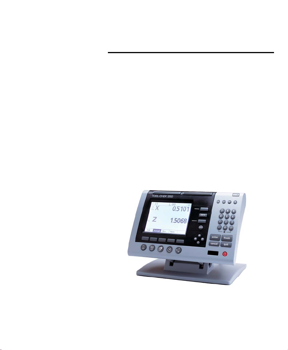
Tool-Chek® 200
User’s Guide
Page 4

Proprietary notice
Disclaimer
All information set forth in this document, all rights to such information, any and all inventions disclosed herein and any patents
that might be granted by employing the materials, methods, techniques or apparatus described herein are the exclusive property
of Metronics Incorporated, Bedford, New Hampshire.
No part of this document may be reproduced, stored in a retrieval
system, or transmitted in any form or by any means, electronic,
mechanical, photocopying, recording, or otherwise, without the
prior permission of Metronics Incorporated. The information contained herein is designed only for use with the Tool-Chek 200 Tool
Presetter Readout. Metronics Incorporated is not responsible for
any use of this information as applied to any other apparatus.
The information contained in this document is subject to change
without notice. Metronics Incorporated assumes no responsibility
or liability for any errors or inaccuracies contained herein, or for
incidental or consequential damage in connection with the furnishing, performance, or use of this guide.
Metronics Inc. shall not be liable to the purchaser of this product
or third parties for damages, losses, costs, or expenses incurred by
the purchaser or third parties as a result of: accident, misuse, or
abuse of this product or unauthorized modifications, repairs, or
alterations to this product, or failure to strictly comply with
Metronics Incorporated’s operating and maintenance instructions.
Trademarks
Metronics, Tool-Chek, Tool-Chek 200, and TC200 are registered
trademarks of Metronics Incorporated.
Other product names used herein are for identification purposes
only and may be trademarks of their respective owners. Metronics
Incorporated disclaims any and all rights to those marks.
Page 5

Safety and
Maintenance
Considerations
Location and
Mounting
Cleaning
General safety precautions must be followed when operating the
system. Failure to observe these precautions could result in damage to the equipment, or injury to personnel. It is understood
that safety rules within individual companies vary. If a conflict
exists between the material contained in this guide and the rules
of a company using this system, the more stringent rules should
take precedence.
Although Metronics strongly recommends that you read all parts
of this guide, it is essential for reliable and safe operation to read
the first portions up to and including Chapter 2: Operation, prior
to operating the TC200.
The TC200 must be placed or mounted on a stable, reliable surface. If the TC200 should fall, it could become seriously damaged
and more importantly could cause injuries to the user.
Use only a cloth dampened with water and a mild detergent for
cleaning the exterior surfaces. Never use abrasive cleaners, and
never use strong detergents or solvents. Only dampen the cloth,
do not use a cleaning cloth that is dripping wet.
Electrical
Do not allow the power cord to be located such that it can be
Page 6

General maintenance
walked on or create a tripping hazard.
WARNINGWARNING
WARNING
WARNINGWARNING
Unplug the TC200 from the electrical outlet before cleaning.Unplug the TC200 from the electrical outlet before cleaning.
Unplug the TC200 from the electrical outlet before cleaning.
Unplug the TC200 from the electrical outlet before cleaning.Unplug the TC200 from the electrical outlet before cleaning.
WARNINGWARNING
WARNING
WARNINGWARNING
The TC200 is equipped with a 3-prong power plug that includesThe TC200 is equipped with a 3-prong power plug that includes
The TC200 is equipped with a 3-prong power plug that includes
The TC200 is equipped with a 3-prong power plug that includesThe TC200 is equipped with a 3-prong power plug that includes
a separate ground connection. Always connect the power pluga separate ground connection. Always connect the power plug
a separate ground connection. Always connect the power plug
a separate ground connection. Always connect the power pluga separate ground connection. Always connect the power plug
to a 3-prong grounded outlet. The use of 2-prong power plugto a 3-prong grounded outlet. The use of 2-prong power plug
to a 3-prong grounded outlet. The use of 2-prong power plug
to a 3-prong grounded outlet. The use of 2-prong power plugto a 3-prong grounded outlet. The use of 2-prong power plug
adapters or any other connection accessories that remove theadapters or any other connection accessories that remove the
adapters or any other connection accessories that remove the
adapters or any other connection accessories that remove theadapters or any other connection accessories that remove the
third grounded connection create a safety hazard and shouldthird grounded connection create a safety hazard and should
third grounded connection create a safety hazard and should
third grounded connection create a safety hazard and shouldthird grounded connection create a safety hazard and should
not be permitted. If a 3-prong grounded outlet is not available,not be permitted. If a 3-prong grounded outlet is not available,
not be permitted. If a 3-prong grounded outlet is not available,
not be permitted. If a 3-prong grounded outlet is not available,not be permitted. If a 3-prong grounded outlet is not available,
ask your electrician to provide one.ask your electrician to provide one.
ask your electrician to provide one.
ask your electrician to provide one.ask your electrician to provide one.
Unplug the TC200 from the wall outlet and seek the assistance of
a qualified service technician if:
• The power cord is frayed or damaged or the power plug is
damaged
• Liquid is spilled or splashed onto the enclosure
• The TC200 has been dropped or the exterior has been dam aged
• The TC200 exhibits degraded performance or indicates a need
for service some other way
Backup battery
charging
FCC compliance statement
The TC200 utilizes an internal battery to maintain system configuration settings during power interruptions. A battery circuit
charges this backup battery during periods of normal operation.
When the TC200 is used on a daily basis, the backup battery will
be adequately charged to maintain configuration settings during
power outages. However, over extended periods of nonuse, the
battery might lose the charge necessary to maintain configuration settings. To keep the backup battery charged over extended
periods of nonuse, apply power to the TC200 and leave it turned
on for a minimum of 2 days each month.
Page 7

FCC Rule NP15R Rev. 23, June, 1989
This equipment has been tested and found to comply with the
limits for a Class A digital device, pursuant to Part 15 of the FCC
Rules. These limits are designed to provide reasonable protection
against harmful interference when the equipment is operated in
a commercial environment. This equipment generates, uses, and
can radiate radio frequency energy and, if not installed and used
in accordance with the instructions in this guide, may cause harmful interference to radio communication. Operation of this equipment in a residential area is likely to cause harmful interference, in
which case the user will be required to correct the interference at
his own expense.
Shielded cables must be used with this unit to ensure compliance
with Class A FCC limits. The connection of a non-shielded equipment interface cable to this equipment will invalidate the FCC Certification of this device and may cause interference levels which
exceed the limits established by the FCC for this equipment. It is
the responsibility of the user to obtain and use a shielded equipment interface cable with this device. Do not leave cables connected to unused interfaces. Changes or modifications not expressly approved by the manufacturer could void the user’s authority to operate the equipment.
For Canadian Users:
This Class “A” digital apparatus meets all requirements of the Canadian Interference-Causing Equipment Regulations.
Declaration of Conformity (EU)
Cet appareil numérique de la classe “A” respecte toutes les exigences
du Reglement sur le matériel brouilleur du Canada.
Page 8

This product conforms to the following product standards:
EN61010-1 Safety
EN61326:1998 EMC
The product therefore conforms with the requirements of the
European Directives on Low Voltage 73/23/EEC and EMC 89/336/
EEC.
Supporting documentation is maintained at Metronics, Inc. USA.
Guide Part Number: 11A10073
Printing History:
September, 2000 First Printing
Revision 1.0
Software Version: 1.00
Printed in the USA
Page 9

Page 10

Page 11

Contents
Introduction ........................................................ i
About this manual ...............................................................................................................i
Who should read this guide ................................................................................................. i
What this guide covers......................................................................................................... i
Conventions and Basic terms ............................................................................................... ii
Measurement polarity ......................................................................................................... ii
Measurementresolution in the guide .................................................................................. ii
Icons ....................................................................................................................................iii
Type styles ...........................................................................................................................iii
Accuracy andprecision......................................................................................................... iii
System configuration ..........................................................................................................iv
and setup ............................................................................................................................iv
Overview .......................................................... 1-1
Proprietary notice ............................................................................................................ 1-4
Disclaimer ......................................................................................................................... 1-4
Trademarks....................................................................................................................... 1-4
Safety and Maintenance Considerations .......................................................................... 1-5
Location and Mounting ................................................................................................... 1-5
Cleaning ........................................................................................................................... 1-5
Electrical ........................................................................................................................... 1-5
General maintenance ....................................................................................................... 1-6
Backup battery charging .................................................................................................. 1-6
FCC compliance statement ............................................................................................... 1-6
For Canadian Users: ......................................................................................................... 1-7
Declaration of Conformity (EU) ........................................................................................ 1-7
Specifications ..................................................................................... 1-5
Input voltage range: ........................................................................................................ 1-5
Fuse:................................................................................................................................. 1-5
Input Frequency: .............................................................................................................. 1-5
Environmental Conditions: ............................................................................................... 1-5
Dimensions: ...................................................................................................................... 1-5
LCD: ................................................................................................................................. 1-5
Resolution: ....................................................................................................................... 1-5
ENC tests: ......................................................................................................................... 1-6
Page 12

Table of Contents
Operation......................................................... 2-1
Getting ready to operate the TC200 ................................................ 2-1
Location and mounting ................................................................................................... 2-2
Power cord and plug ....................................................................................................... 2-2
Power surge suppressor ................................................................................................... 2-2
Liquids .............................................................................................................................. 2-2
Configuration and system setup ...................................................................................... 2-2
Checking connections ...................................................................................................... 2-2
Applying power ................................................................................. 2-3
Initial system settings ....................................................................... 2-4
Adjusting LCD tilt ............................................................................................................. 2-4
Adjusting LCD brightness ................................................................................................. 2-4
Setting measurement and display parameters ................................................................. 2-4
Diameter/Radius ............................................................................................................... 2-4
Absolute/Incremental ....................................................................................................... 2-4
Unit of measure (Linear)................................................................................................... 2-5
Help ................................................................................................................................. 2-5
Feature selection keys....................................................................... 2-6
Setting gage ....................................................................................................................2-6
Tool .................................................................................................................................. 2-6
Tool Sequence .................................................................................................................. 2-6
Circle ................................................................................................................................ 2-6
Angle ............................................................................................................................... 2-7
Basic operating .................................................................................. 2-8
procedures ......................................................................................... 2-8
To measure and store a setting gage ............................................................................... 2-8
To measure and store a tool........................................................................................... 2-12
Creating a tool sequence ............................................................................................... 2-14
Running a tool sequence ............................................................................................... 2-16
Measuring a circle............................................................................ 2-19
To measure a circle ......................................................................................................... 2-19
Measuring an angle......................................................................... 2-22
To measure an angle ...................................................................................................... 2-22
Zeroing Axes .................................................................................................................. 2-25
Freezing Axes ................................................................................................................. 2-25
Contents-2
Page 13

Tool-Chek® TC200
Setup................................................................ 3-1
Configuring the TC200 ...................................................................... 3-1
Basic setup terms............................................................................... 3-1
Accessing the ..................................................................................... 3-2
Setup menu ........................................................................................ 3-2
Using the ............................................................................................ 3-3
Setup menu ........................................................................................ 3-3
Setup Instructions ............................................................................. 3-3
Command Keys .................................................................................. 3-4
Enter Key .......................................................................................................................... 3-4
Finish Key ......................................................................................................................... 3-4
Cancel Key........................................................................................................................ 3-4
Quit Key ........................................................................................................................... 3-4
Supervisor Password ......................................................................... 3-5
To enter the password ..................................................................................................... 3-5
About .................................................................................................. 3-6
Display ................................................................................................ 3-6
MM Disp Res.....................................................................................................................3-8
Inch Disp Res .................................................................................................................... 3-8
DMS Disp Res ................................................................................................................... 3-9
DD Disp Res .................................................................................................................... 3-10
Startup Linear ................................................................................................................ 3-10
Startup Angular ............................................................................................................. 3-11
Radix .............................................................................................................................. 3-11
Current Angular............................................................................................................. 3-12
Encoders ........................................................................................... 3-12
Axis ................................................................................................................................3-13
Resolution (Res) .............................................................................................................. 3-13
Type ............................................................................................................................... 3-14
Reference Marks ............................................................................................................ 3-14
MZ Cnts.......................................................................................................................... 3-15
Reversed ......................................................................................................................... 3-15
Interpolation .................................................................................................................. 3-16
Units............................................................................................................................... 3-16
Print .................................................................................................. 3-17
Auto Label ..................................................................................................................... 3-17
Auto Report ................................................................................................................... 3-18
Label Format .................................................................................................................. 3-18
Pre Line .......................................................................................................................... 3-19
Post Line......................................................................................................................... 3-19
Contents-3
Page 14

Table of Contents
Pre Form......................................................................................................................... 3-19
Post Form .......................................................................................................................3-20
Print Report ....................................................................................................................3-20
Label Lines ...................................................................................................................... 3-20
Skip Lines ....................................................................................................................... 3-21
Label Indent ................................................................................................................... 3-21
Ports.................................................................................................. 3-23
Baud ............................................................................................................................... 3-24
Word Len (word length) ................................................................................................ 3-24
Stop Bits......................................................................................................................... 3-24
Parity .............................................................................................................................. 3-25
Handshake ..................................................................................................................... 3-25
Data/ Parallel Data.......................................................................................................... 3-26
EOC Delay (end of character delay) ................................................................................ 3-26
EOL Delay (end of line delay).......................................................................................... 3-27
Squareness ....................................................................................... 3-28
Angle ............................................................................................................................. 3-28
Master Axis.....................................................................................................................3-29
Error Correction ............................................................................... 3-30
Linear Error Correction (LEC) .......................................................... 3-31
Segmented Linear Error Correction (SLEC) ................................... 3-33
Misc. (miscellaneous) ...................................................................... 3-35
Key Delay........................................................................................................................ 3-35
Volume ........................................................................................................................... 3-35
Libraries ............................................................................................ 3-35
Use Locations ................................................................................................................. 3-36
Tool Button .................................................................................................................... 3-36
SG 00 master .................................................................................................................. 3-37
SG Edit Lock ................................................................................................................... 3-37
SG Cal Lock .................................................................................................................... 3-38
Tool Sequence Edit Lock ................................................................................................. 3-38
Clock ................................................................................................. 3-39
Year ................................................................................................................................ 3-39
Month ............................................................................................................................ 3-40
Day................................................................................................................................. 3-40
Hours ............................................................................................................................. 3-40
Minutes .......................................................................................................................... 3-41
Seconds.......................................................................................................................... 3-41
Date Format ................................................................................................................... 3-41
Time Format ................................................................................................................... 3-42
Contents-4
Page 15

Tool-Chek® TC200
Communications ............................................. 4-1
RS232 port .......................................................................................... 4-1
Default settings ................................................................................. 4-2
Ports section of Setup menu: ........................................................................................... 4-2
Print section of Setup menu: ........................................................................................... 4-2
Feature print formats ........................................................................ 4-3
Feature Formats................................................................................. 4-4
Print Setup ......................................................................................... 4-4
Pre Line ............................................................................................................................ 4-5
Post Line........................................................................................................................... 4-5
Pre Form........................................................................................................................... 4-5
Post Form ......................................................................................................................... 4-5
Print Report ...................................................................................................................... 4-5
Print Labels....................................................................................................................... 4-6
Print POT .......................................................................................................................... 4-6
Num Label Lines ............................................................................................................... 4-6
Num Skip Lines ................................................................................................................. 4-6
Amt Label Indent ............................................................................................................. 4-6
Glossary .............................................................................................. 1-6
IndexIndex
Index
IndexIndex
......................................................................................................
...................................................
......................................................................................................
Index-1Index-1
Index-1
Index-1Index-1
Contents-5
Page 16

Table of Contents
Contents-6
Page 17

About this manual
Who should read
this guide
What this guide
covers
Introduction
The material in this guide is divided into 4 chapters ranging from
introductory material to advanced topics. If you are an advanced
user of tool presetter readouts, feel free to skim the material contained in this guide, but do not begin to operate the readout
unless you’re confident that you understand the essential information contained in these chapters. Observe all precautions and
safety rules while using this equipment.
After an initial review, this guide will become an invaluable reference source that can be used routinely to answer questions and
ensure smooth continued operation of the Tool-Chek. The comprehensive table of contents and index facilitate rapid access to
specific information contained within the guide.
This user’s guide is intended for operators, technicians, supervisors and dealer representatives.
Chapter 1: Overview
An overview of TC200 system including specifications.
Chapter 2: Operation
Demonstration of TC200 operation for getting started with a minimum of details.
Chapter 3: Setup
Contains an explanation of the various menu functions found on
the TC200.
Chapter 4: Communications
Serial (RS232) and parallel communication with printers and IBMcompatible personal computers.
i
Page 18

Introduction
Conventions and
Basic terms
Measurement polarity
The terms Tool-Chek 200, TC200 and system used in this guide
refer to the Tool-Chek 200 tool presetter readout.
A program is simply a series or sequence of key-presses used to
perform measurements and stored by the system to be repeated
automatically later. The stored sequence (program) can be repeated later simply by pressing one user-defined key.
It is assumed in all discussions of measurements that:
• Moving crosshairs to the right causes measure counts to
increase in a positive direction; 1 to 2 to 3 and so on.
• Moving crosshairs up causes measure counts to increase
in a positive direction; 1 to 2 to 3 and so on.
• Rotating crosshairs counterclockwise causes measure counts
to increase in a positive direction; 1 degree to 2 degrees to
3 degrees and so on.
• This count direction can easily be reversed if necessary.
Reversing the count direction is discussed later in Chapter 6:
Orthogonal axis calibration.
Measurement
resolution in
the guide
ii
In most cases the display resolution shown on screens in this guide
will be one ten-thousandths of an inch (0.0001) or two microns
metric (0.002). The display resolutions shown in this manual are
not meant to suggest resolutions that should be set on your system, they are only examples.
Page 19

Icons
Tool-Chek® TC200
This guide uses the following icons to highlight information:
The raised hand icon indicates a warning regarding a situation or
condition that could lead to personal injury or death. You should
not proceed until you read and thoroughly understand the warning message. Warning messages are shown in bold type.
The exclamation point icon indicates a caution regarding a situation or condition that could lead to equipment malfunction or
damage. You should not proceed until you read and fully understand the caution message. Caution messages are shown in bold
type.
The note icon indicates additional or supplementary information
about an activity or concept. Notes are shown in bold type.
Type styles
Accuracy and
precision
Warnings, cautions, notes and the titles of front panel keys or
system commands and menus shown in instructions are shown in
bold type.
The TC200 is capable of great accuracy and precision and may
surpass the measurement-accuracy capability of the human operator. The system is also capable of displaying higher resolution
and more significant figures than is often needed. These facts
may be important in your interpretation and use of the measurement data provided by the system.
iii
Page 20

Introduction
System configuration
and setup
Metronics, Incorporated assumes that all TC200 systems will be
configured and setup for the end-user by dealer representatives
or OEMs. This setup includes calibration according to the user’s
tool presetter if needed.
When the end-user installs a new tool presetter, it will probably
be necessary to perform configuration and setup again. In that
case, contact their dealer representatives for assistance.
WARNINGWARNING
WARNING
WARNINGWARNING
There is never any reason to open the TC200 enclosure. ThereThere is never any reason to open the TC200 enclosure. There
There is never any reason to open the TC200 enclosure. There
There is never any reason to open the TC200 enclosure. ThereThere is never any reason to open the TC200 enclosure. There
are no user-serviceable components or assemblies inside. Asare no user-serviceable components or assemblies inside. As
are no user-serviceable components or assemblies inside. As
are no user-serviceable components or assemblies inside. Asare no user-serviceable components or assemblies inside. As
with any electronic instrument, there is a danger of electricalwith any electronic instrument, there is a danger of electrical
with any electronic instrument, there is a danger of electrical
with any electronic instrument, there is a danger of electricalwith any electronic instrument, there is a danger of electrical
shock and damage to the instrument if the enclosure is opened.shock and damage to the instrument if the enclosure is opened.
shock and damage to the instrument if the enclosure is opened.
shock and damage to the instrument if the enclosure is opened.shock and damage to the instrument if the enclosure is opened.
Refer all maintenance requirements to your original dealerRefer all maintenance requirements to your original dealer
Refer all maintenance requirements to your original dealer
Refer all maintenance requirements to your original dealerRefer all maintenance requirements to your original dealer
failing that to Metronics Incorporated.failing that to Metronics Incorporated.
failing that to Metronics Incorporated.
failing that to Metronics Incorporated.failing that to Metronics Incorporated.
, or, or
, or
, or, or
iv
Page 21
Chapter 1
Overview
The Tool-Chek 200 is an advanced tool presetter readout system
that allows the user to establish datums using a setting gage and
measure tool offset relative to nominal dimensions. Using the
TC200 you can create a tool sequence to perform a series of commonly repeated tool measurements. Measurement results can be
viewed on the TC200’s LCD display, sent to a printer, or downloaded to a computer. The TC200 supports a variety of reporting
formats for the user to select.
The intuitive interface will be familiar to users of the Tool-Chek
and other Metronics products. Operators will find the TC200 easy
to understand and use thanks to a large LCD display and front
panel keys clearly marked with familiar function and mode symbols.
1-1
Page 22
Chapter 1 Overview
The LCD displays alphanumeric information that enables the user
to perform simple offset measurements or more complex tool presetting and sequencing functions. It’s size allows pertinent information to be clearly displayed and eliminates the need to page or
scroll for information.
1-2
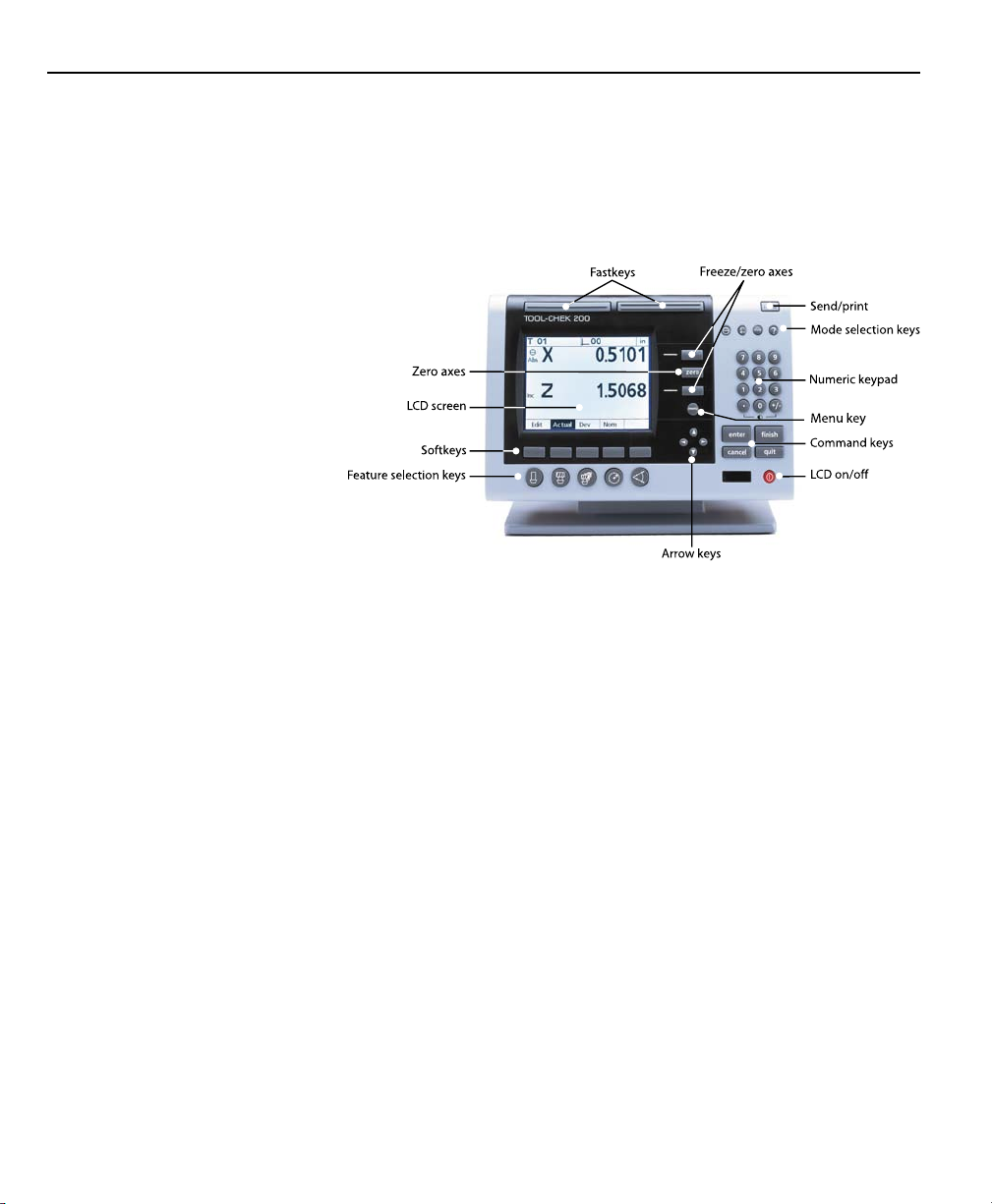
Many of the features and symbols from previous Tool-Chek version are retained in the TC200. The feature selection keys and the
features they activate will be familiar to most Tool-Chek users.
Additional ‘softkeys’ expand the functionality of the TC200 and
make the interface more user-friendly. Softkeys are used to access additional groups of related functions. To access softkey functions simply press the softkey beneath the desired group.
User’s can navigate through lists using the arrow keys and enter
numeric information via
the numeric keypad.
Page 23
Tool-Chek® TC200
Commonly executed tasks can be programmed into the TC200
and activated via one of the two Fast keys at the top of the readout.
All front panel keys provide tactile sensory feedback, and many
keypress operations can be configured by supervisors or dealer
representatives to generate an audible sound.
Speaker and external speaker jack outputs are provided that can
be adjusted for quiet or noisy environments. Earphones can be
plugged into the external speaker jack to facilitate silent operation in quiet environments.
The compact ergonomic design and adjustable-tilt front panel of
the TC200 allows users to locate and mount the instrument in a
wide variety of environments. The tilt front panel can be adjusted
and secured in any convenient position. Rubber feet on the bottom prevent slipping when the is not permanently bolted to a
work surface. Bolt holes are provided in the mounting stand that
match the pattern of the TC2000.
1-3
Page 24
Chapter 1 Overview
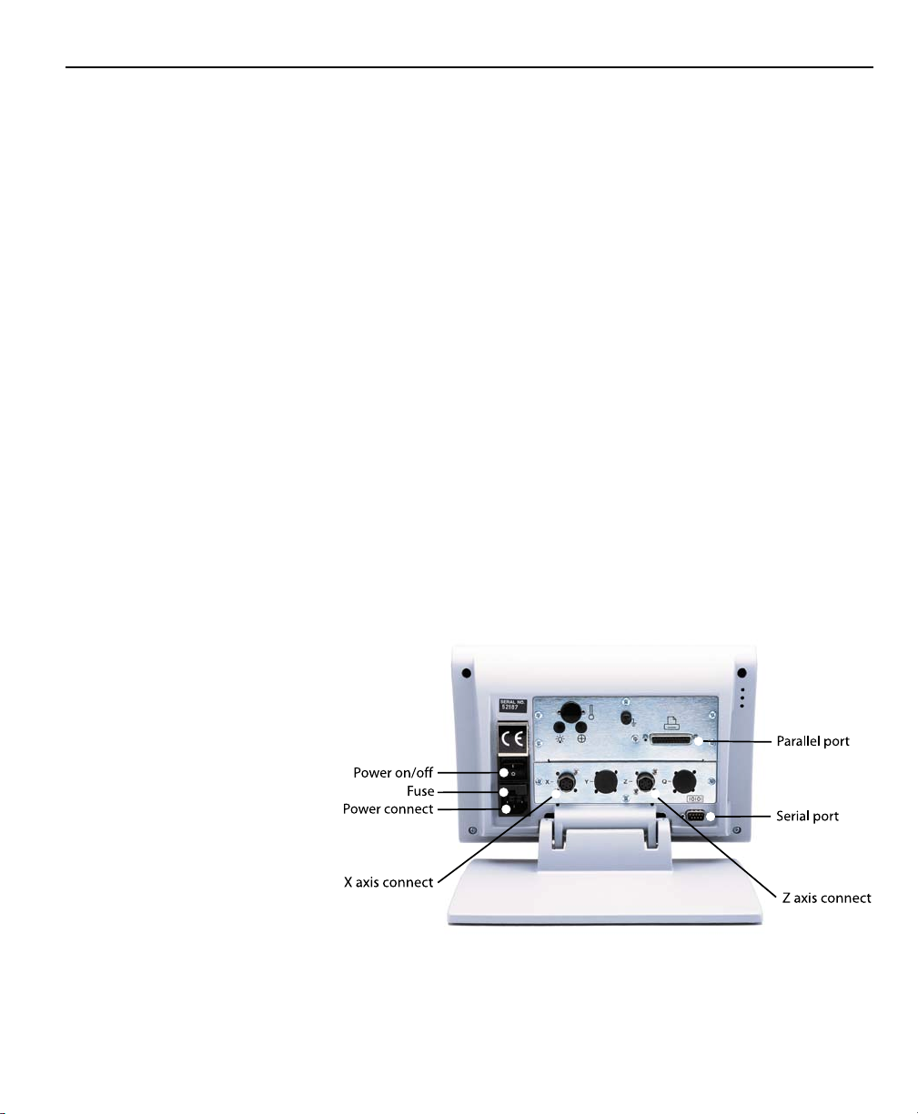
Measurements viewed on the front panel LCD can be transmitted
to an IBM-compatible personal computer over a standard parallel
port connection, or to a printer over a parallel or serial port.
Sequences of keypresses used to perform measurements can be
recorded and stored as programs. These programs can be replayed later to perform complete measurement sequences. Sequences can be as simple as measuring a line, or can be expanded
to include skew adjustment, the measurement of multiple features and printing reports of measurement results.
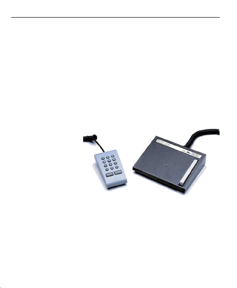
An optional foot switch and remote keypad are available for feature-point and numeric data entry when the user is not close to
the front panel.
1-4
Page 25

Specifications
Tool-Chek® TC200
Input voltage range:
85 VAC to 264 VAC. 100 W maximum (Auto switchable)
Fuse:
1.6 Amp 250V Type T
CAUTIONCAUTION
CAUTION
CAUTIONCAUTION
Fuses provide protection against fire and other damage.Fuses provide protection against fire and other damage.
Fuses provide protection against fire and other damage.
Fuses provide protection against fire and other damage.Fuses provide protection against fire and other damage.
Replacement fuses MUST match the specified voltage and currentReplacement fuses MUST match the specified voltage and current
Replacement fuses MUST match the specified voltage and current
Replacement fuses MUST match the specified voltage and currentReplacement fuses MUST match the specified voltage and current
ratings.ratings.
ratings.
ratings.ratings.
Input Frequency:
47Hz to 63Hz
Environmental Conditions:
Temperature: 0C to 45C (32F to 113F) non-condensing
Humidity: 90%rh
Altitude: 2000 meters
Pollution degree: 2
Installation category: II
Dimensions:
Enclosure: (WxHxD): 11.5" X 7.5" X 2.75"
Base (WxHxD): 10"X 2" X 7.8"
Enclosure weight: 3.5 lbs.
Base weight: 7lbs.
LCD:
Size/color: 6" black and white
Display digit size: 0.5"
Resolution:
1-5
Page 26

Chapter 1 Overview
0.000004" or 0.0001mm
ENC tests:
EN61326:1998
EMC for electrical equipment for measurement, control, and laboratory use
EN61010
Safety requirements for electrical equipment for measurement,
control, and laboratory use
WARNING:WARNING:
WARNING:
WARNING:WARNING:
TT
o reduce the risk of electrical shock, never remove the cover oro reduce the risk of electrical shock, never remove the cover or
T
o reduce the risk of electrical shock, never remove the cover or
TT
o reduce the risk of electrical shock, never remove the cover oro reduce the risk of electrical shock, never remove the cover or
open the enclosure. There are no user-serviceable parts inside.open the enclosure. There are no user-serviceable parts inside.
open the enclosure. There are no user-serviceable parts inside.
open the enclosure. There are no user-serviceable parts inside.open the enclosure. There are no user-serviceable parts inside.
Refer all service requirements to qualified service personnel.Refer all service requirements to qualified service personnel.
Refer all service requirements to qualified service personnel.
Refer all service requirements to qualified service personnel.Refer all service requirements to qualified service personnel.
1-6
Page 27

Chapter 2
Operation
This chapter demonstrates the operation of the Tool-Chek 200.
This demonstration is provided to allow experienced operators to
start using the TC200 immediately. The demonstration will be
most helpful if you perform the indicated steps on your TC200
while reading this material.
NOTENOTE
NOTE
NOTENOTE
Illustrations are included in this manual to indicate the basicIllustrations are included in this manual to indicate the basic
Illustrations are included in this manual to indicate the basic
Illustrations are included in this manual to indicate the basicIllustrations are included in this manual to indicate the basic
types or displays found while operating the TC200. Specifictypes or displays found while operating the TC200. Specific
types or displays found while operating the TC200. Specific
types or displays found while operating the TC200. Specifictypes or displays found while operating the TC200. Specific
data (i.e. measurements) will vary according to user selections.data (i.e. measurements) will vary according to user selections.
data (i.e. measurements) will vary according to user selections.
data (i.e. measurements) will vary according to user selections.data (i.e. measurements) will vary according to user selections.
It is not necessary to match actual measurements to thoseIt is not necessary to match actual measurements to those
It is not necessary to match actual measurements to those
It is not necessary to match actual measurements to thoseIt is not necessary to match actual measurements to those
presented here.presented here.
presented here.
presented here.presented here.
The demonstration will include:
• Getting ready to operate the TC200
• Applying power
• Initial system settings
• Measuring and storing a setting gage
• Measuring and entering a tool
• Creating a tool sequence
• Measuring a circle
• Measuring an angle
Getting ready to operate the TC200
The contents of LCD screens used in this demonstration will reflect a system using X and Z axis encoders configured with factory
default settings.
This demonstration assumes a basic familiarity with the process of
measuring features, TC200 controls and indicators, and the types
of information presented on LCD screens.
2-1
Page 28

Chapter 2 Operation
NOTENOTE
NOTE
NOTENOTE
It is assumed that operators have a basic understanding of toolIt is assumed that operators have a basic understanding of tool
It is assumed that operators have a basic understanding of tool
It is assumed that operators have a basic understanding of toolIt is assumed that operators have a basic understanding of tool
fixturing and the geometric probing techniques required for theirfixturing and the geometric probing techniques required for their
fixturing and the geometric probing techniques required for their
fixturing and the geometric probing techniques required for theirfixturing and the geometric probing techniques required for their
tool presetting devices.tool presetting devices.
tool presetting devices.
tool presetting devices.tool presetting devices.
Location and mounting
Verify that the TC200 is mounted on a stable reliable surface. If it
should fall, it could become seriously damaged or cause injuries to
the user.
Power cord and plug
The power cord should not be located where it can be walked on
or create a tripping hazard. Always connect the 3-prong power
plug to a 3-prong grounded outlet. Use of a 2-prong power plug
adapter or any other connection accessory that removes the third
grounded connection creates a safety hazard and should not be
permitted.
Power surge suppressor
A high-quality power surge suppressor should be used to limit the
amplitude of potentially damaging power line transients caused
by the operation of heavy electrical machinery or lightning.
2-2
Liquids
Do not spill or splash liquids on the TC200 enclosure.
Configuration and system setup
System configuration and setup should be performed only by technically qualified supervisors or dealer representatives. Operators
should not attempt to alter the configuration of the TC200
Checking connections
Perform a routine inspection of all connections to the tool preset
readout system. Connections should be clean and tight. Cables
should be located away from moving objects and should not create tripping hazards.
Cables connected to the parallel and serial (RS232) output ports
should be shielded and should be terminated and firmly connected
on both ends.
Page 29
Applying power
Tool-Chek® TC200
CAUTIONCAUTION
CAUTION
CAUTIONCAUTION
Never connect electrical cables to the system when the power isNever connect electrical cables to the system when the power is
Never connect electrical cables to the system when the power is
Never connect electrical cables to the system when the power isNever connect electrical cables to the system when the power is
on. Optical edge detector cables may be connected oron. Optical edge detector cables may be connected or
on. Optical edge detector cables may be connected or
on. Optical edge detector cables may be connected oron. Optical edge detector cables may be connected or
disconnected with the power on.disconnected with the power on.
disconnected with the power on.
disconnected with the power on.disconnected with the power on.
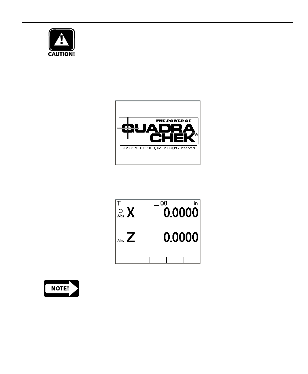
To apply power, press the power switch located at the back of the
enclosure to ON (1). The system will initialize and display the powerup screen.
Press any key on the front panel to complete the system initialization. The DRO screen will be displayed showing the current positions of encoders on each axis.
NOTENOTE
NOTE
NOTENOTE
If the encoders used with your system include reference marks,If the encoders used with your system include reference marks,
If the encoders used with your system include reference marks,
If the encoders used with your system include reference marks,If the encoders used with your system include reference marks,
you may be instructed to cross the reference marks on each axisyou may be instructed to cross the reference marks on each axis
you may be instructed to cross the reference marks on each axis
you may be instructed to cross the reference marks on each axisyou may be instructed to cross the reference marks on each axis
before the DRO screen is displayed.before the DRO screen is displayed.
before the DRO screen is displayed.
before the DRO screen is displayed.before the DRO screen is displayed.
2-3
Page 30
Chapter 2 Operation
Initial system settings
The first steps in any measurement session will include adjusting
the LCD viewing angle, contrast and measurement or display settings.
Adjusting LCD tilt
The tilt angle of the TC200 enclosure can usually be adjusted for
optimum viewing by simply swiveling the enclosure on its base to
the desired position. If the enclosure angle is locked in position,
loosen the two Allen screws at the base of the enclosure, move
the enclosure to the desired angle and tighten the Allen screws so
that the enclosure is held firmly in position but can be adjusted
again without loosening the Allen screws.
Adjusting LCD brightness
The LCD contrast can be adjusted for optimum viewing from the
DRO screen. Press the decimal point of the numeric keypad to
decrease contrast or the +/- key to increase contrast.
Setting measurement and display parameters
The measure and display parameters that you establish prior to a
measurement session will depend on the measurement that you
are making and the way you would like to have data and graphics
displayed on the LCD screen and on reports.
2-4
Diameter/Radius
Select diameter or radius measurement by pressing the Diameter/
Radius mode key. This selection can be changed at any time.
NOTENOTE
NOTE
NOTENOTE
When the user changes the mode from diameter or radius theWhen the user changes the mode from diameter or radius the
When the user changes the mode from diameter or radius the
When the user changes the mode from diameter or radius theWhen the user changes the mode from diameter or radius the
value entered remains the same. Be certain to adjust the valuevalue entered remains the same. Be certain to adjust the value
value entered remains the same. Be certain to adjust the value
value entered remains the same. Be certain to adjust the valuevalue entered remains the same. Be certain to adjust the value
entered to obtain accurate presets.entered to obtain accurate presets.
entered to obtain accurate presets.
entered to obtain accurate presets.entered to obtain accurate presets.
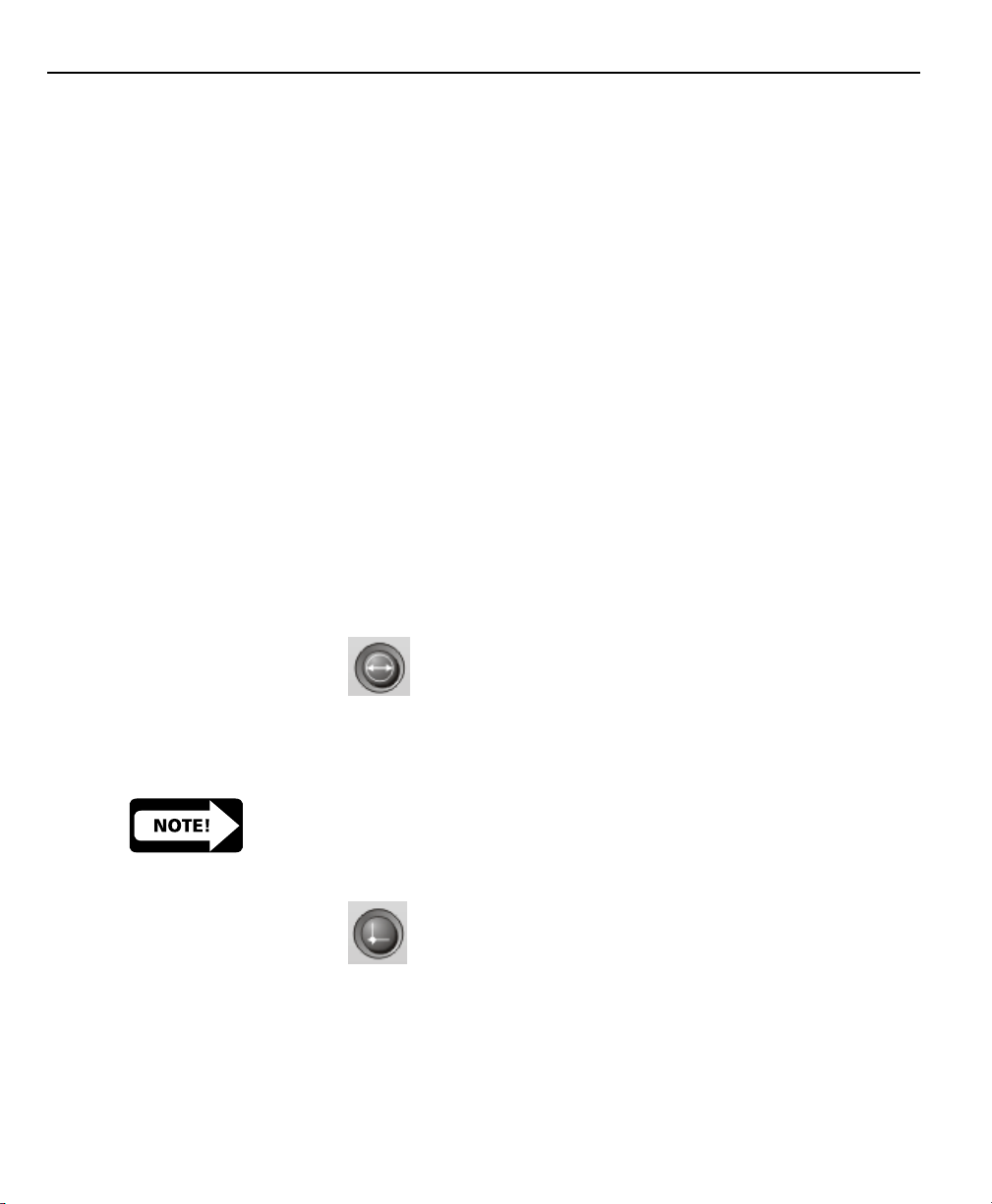
Absolute/Incremental
Select absolute or incremental modes for the X and Z axis by pressing the Absolute/Incremental mode key. When the Absolute/Incremental mode key is pressed the user is prompted to select the
axis to be changed to incremental mode. To select either the X or
Z axis press the axis key. To switch both axes to incremental press
Page 31

Tool-Chek® TC200
the zero key. Pressing the Absolute/Incremental mode key a second time will return both axes to absolute. Both axes are can be
changed to incremental by simply pressing the zero button and
following the on-screen instructions.
Unit of measure (Linear)
Features can be displayed in mm or inches. Select the desired unit
of measure if necessary by pressing the mm/inch mode key. The
unit of measure will be displayed at the upper right corner of the
LCD. This selection can be changed at any time.
Help
Displays help text on the screen explaining the current function or
LCD screen.
2-5
Page 32

Chapter 2 Operation
Feature selection keys
The feature selection keys initiate TC200 functions that measure
and calculate setting gage and tool dimensions, store tool sequencing programs, and initiate other automated features.
Setting gage
Setting gages are used to establish a datum on the tool presetter.
Pressing this key brings up the Select Setting Gage screen. The
user can input new, edit existing, and delete unneeded setting
gages with softkey functions on this screen. All tool presetting
operations require at least one setting gage.
Tool
Allows the user to input nominal information for a tool. Pressing
this key brings up the New Tool screen. The user can input information to store a new tool on this screen. New tools can be
saved by pressing the save softkey. Existing tools can be selected
by pressing the select softkey.
2-6
Tool Sequence
Allows the user to program a series of tool measurements required for a specific part. Pressing this key brings up the recording screen. The TC200 will record all keypresses and user selections and store them for later use. Users can retrieve a tool sequence using this key as well.
Circle
Circles can be measured by targeting between 3 and 100 points
around the circumference. Generally, accuracy of the feature is
increased as more points are targeted and the targeted points are
Page 33

Tool-Chek® TC200
distributed at more or less equal arc distances around the circle.
When more than 3 points are targeted, a best-fit algorithm will be
used to create the circle feature and an F (Form) value will be
included in the circle feature data.
Angle
Angles can be measured by targeting between 2 and 100 points
on each of the vertices of the angle. Generally, accuracy of the
feature is increased as more points are targeted and the targeted
points are distributed at more or less equal distances along the
line.
2-7
Page 34
Chapter 2 Operation
Basic operating
procedures
To measure and store a setting gage
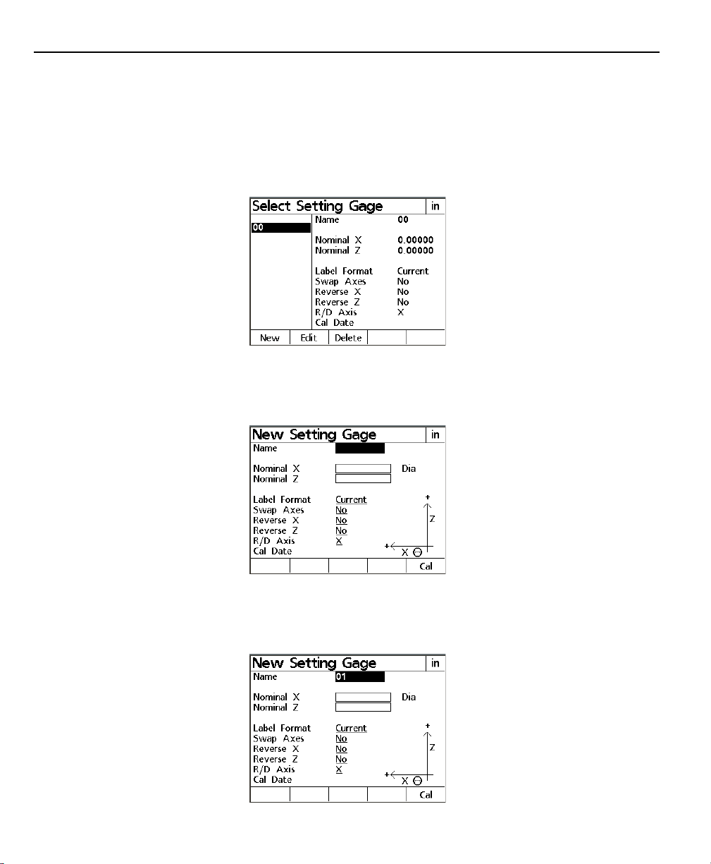
Step 1
From the feature selection keys press setting gage. The LCD displays the select setting gage screen.
Step 2
Press the new softkey. The LCD displays the new setting gage
screen.
2-8
Step 3
Use the numerical keypad to enter a name for the setting gage
and then press enter.
Page 35

Tool-Chek® TC200
Step 4
Enter the value for Nominal X. Nominal X is the diameter or radius
of the setting gage. Press enter.
NOTENOTE
NOTE
NOTENOTE
The TC200 displays either ‘Dia’ or ‘Rad’ next to input field forThe TC200 displays either ‘Dia’ or ‘Rad’ next to input field for
The TC200 displays either ‘Dia’ or ‘Rad’ next to input field for
The TC200 displays either ‘Dia’ or ‘Rad’ next to input field forThe TC200 displays either ‘Dia’ or ‘Rad’ next to input field for
Nominal X to indicate whether the value is a diameter or radius.Nominal X to indicate whether the value is a diameter or radius.
Nominal X to indicate whether the value is a diameter or radius.
Nominal X to indicate whether the value is a diameter or radius.Nominal X to indicate whether the value is a diameter or radius.
This indication can be changed by pressing the Diameter/RadiusThis indication can be changed by pressing the Diameter/Radius
This indication can be changed by pressing the Diameter/Radius
This indication can be changed by pressing the Diameter/RadiusThis indication can be changed by pressing the Diameter/Radius
mode selection keymode selection key
mode selection key
mode selection keymode selection key
NOTENOTE
NOTE
NOTENOTE
When the user changes the mode from diameter or radius theWhen the user changes the mode from diameter or radius the
When the user changes the mode from diameter or radius the
When the user changes the mode from diameter or radius theWhen the user changes the mode from diameter or radius the
value entered remains the same. Be certain to adjust the valuevalue entered remains the same. Be certain to adjust the value
value entered remains the same. Be certain to adjust the value
value entered remains the same. Be certain to adjust the valuevalue entered remains the same. Be certain to adjust the value
entered to obtain accurate presets.entered to obtain accurate presets.
entered to obtain accurate presets.
entered to obtain accurate presets.entered to obtain accurate presets.
..
.
..
NOTENOTE
NOTE
NOTENOTE
Be certain to use the correct units of measurement to avoidBe certain to use the correct units of measurement to avoid
Be certain to use the correct units of measurement to avoid
Be certain to use the correct units of measurement to avoidBe certain to use the correct units of measurement to avoid
errors. The units of measure are displayed at the top right cornererrors. The units of measure are displayed at the top right corner
errors. The units of measure are displayed at the top right corner
errors. The units of measure are displayed at the top right cornererrors. The units of measure are displayed at the top right corner
of the screen. Tof the screen. T
of the screen. T
of the screen. Tof the screen. T
inches mode selection keyinches mode selection key
inches mode selection key
inches mode selection keyinches mode selection key
Step 5
Enter the value for Nominal Z. Nominal Z via the distance from
the datum to the tip of the setting gage. Press enter.
o change the units of measure press the mm/o change the units of measure press the mm/
o change the units of measure press the mm/
o change the units of measure press the mm/o change the units of measure press the mm/
..
.
..
2-9
Page 36

Chapter 2 Operation
Step 6
Press the list softkey and use the up or down arrow keys to choose
label formats and press enter.
Step 7
The swap axes feature allows the user to swap the X and Z axis.
Use the softkeys to select yes or no and press enter.
2-10
Step 8
The reverse X feature allows the user to reverse the positive and
negative ends of the X axis. Use the softkeys to select yes or no
and press enter.
Page 37

Tool-Chek® TC200
NOTENOTE
NOTE
NOTENOTE
It may be necessary to reverse axes when presetting lathe toolsIt may be necessary to reverse axes when presetting lathe tools
It may be necessary to reverse axes when presetting lathe tools
It may be necessary to reverse axes when presetting lathe toolsIt may be necessary to reverse axes when presetting lathe tools
to achieve positive offset values.to achieve positive offset values.
to achieve positive offset values.
to achieve positive offset values.to achieve positive offset values.
Step 9
The reverse Z feature allows the user to reverse the positive and
negative ends of the Z axis. Use the softkeys to select yes or no
and press enter.
NOTENOTE
NOTE
NOTENOTE
It may be necessary to swap axes when presetting lathe tools toIt may be necessary to swap axes when presetting lathe tools to
It may be necessary to swap axes when presetting lathe tools to
It may be necessary to swap axes when presetting lathe tools toIt may be necessary to swap axes when presetting lathe tools to
achieve positive offset values.achieve positive offset values.
achieve positive offset values.
achieve positive offset values.achieve positive offset values.
Step 10
The R/D Axis feature allows the user to designate the X or Z axis as
the diameter/radius of the setting gage. Use the softkeys to select X or Z and press finish.
2-11
Page 38

Chapter 2 Operation
Step 11
Align the setting gage with the crosshairs on the tool presetter
and press enter. The TC200 will store the setting gage in its
memory.
To measure and store a tool
Step 1
From the feature selection keys press tool. The LCD displays the
New Tool screen.
2-12
Step 2
Use the numeric keypad to enter a number for the tool and press
enter.
Step 3
Position of tool (POT) refers to a tools location in a tool changer
mechanism. Use the numeric keypad to enter a value between 1
and 99 then press enter.
Step 4
Nominal X is the diameter or radius of the tool. Use the numeric
keypad to enter a value for nominal X and press enter.
Page 39

Tool-Chek® TC200
NOTENOTE
NOTE
NOTENOTE
The TC200 displays either ‘Dia’ or ‘Rad’ next to input field forThe TC200 displays either ‘Dia’ or ‘Rad’ next to input field for
The TC200 displays either ‘Dia’ or ‘Rad’ next to input field for
The TC200 displays either ‘Dia’ or ‘Rad’ next to input field forThe TC200 displays either ‘Dia’ or ‘Rad’ next to input field for
Nominal X to indicate whether the value is a diameter or radius.Nominal X to indicate whether the value is a diameter or radius.
Nominal X to indicate whether the value is a diameter or radius.
Nominal X to indicate whether the value is a diameter or radius.Nominal X to indicate whether the value is a diameter or radius.
This indication can be changed by pressing the Diameter/RadiusThis indication can be changed by pressing the Diameter/Radius
This indication can be changed by pressing the Diameter/Radius
This indication can be changed by pressing the Diameter/RadiusThis indication can be changed by pressing the Diameter/Radius
mode selection keymode selection key
mode selection key
mode selection keymode selection key
NOTENOTE
NOTE
NOTENOTE
Be certain to use the correct units of measurement to avoidBe certain to use the correct units of measurement to avoid
Be certain to use the correct units of measurement to avoid
Be certain to use the correct units of measurement to avoidBe certain to use the correct units of measurement to avoid
errors. The units of measure are displayed at the top right cornererrors. The units of measure are displayed at the top right corner
errors. The units of measure are displayed at the top right corner
errors. The units of measure are displayed at the top right cornererrors. The units of measure are displayed at the top right corner
of the screen. Tof the screen. T
of the screen. T
of the screen. Tof the screen. T
inches mode selection keyinches mode selection key
inches mode selection key
inches mode selection keyinches mode selection key
Step 5
Nominal Z is the length of the tool. Use the numeric keypad to
enter a value for nominal Z and press enter.
Step 6
Enter the name of the setting gage to be used with this tool. The
setting gage name may be entered with the numeric keypad or by
pressing the list softkey. When using the list softkey, use the up or
down arrow keys to scroll through the list. Highlight the setting
gage to be used and press enter. If the setting gage has not been
entered the user will be unable to save the tool data.
..
.
..
o change the units of measure press the mm/o change the units of measure press the mm/
o change the units of measure press the mm/
o change the units of measure press the mm/o change the units of measure press the mm/
..
.
..
Step 7
The TC200 allows the user to store the location of tools in the
location field. Location refers to the physical storage location of
the tool and not the position of the tool (POT) in the automated
tool changer. Entries in this field are optional. Use the numerical
keypad to enter the tool location and press enter. To continue
without entering a location simply press enter.
2-13
Page 40

Chapter 2 Operation
Step 8
The TC200 includes additional inputs for radius and angle for specialized cutting tools. For conventional milling procedures these
fields are left blank.
Step 9
Press the save softkey to save the tool. The TC200 displays the
tool just created.
Creating a tool sequence
The TC200 records user input and store it as a tool sequence. Tool
sequences can be saved for repeated use or modified for slightly
different tasks. For more on modifying tool sequences see Chapter 3: operation.
NOTENOTE
NOTE
NOTENOTE
While recording a tool sequence, use the cancel key to return toWhile recording a tool sequence, use the cancel key to return to
While recording a tool sequence, use the cancel key to return to
While recording a tool sequence, use the cancel key to return toWhile recording a tool sequence, use the cancel key to return to
a previously recorded tool. Pressing cancel once brings up thea previously recorded tool. Pressing cancel once brings up the
a previously recorded tool. Pressing cancel once brings up the
a previously recorded tool. Pressing cancel once brings up thea previously recorded tool. Pressing cancel once brings up the
previous tool; to go back three tools press cancel three times,previous tool; to go back three tools press cancel three times,
previous tool; to go back three tools press cancel three times,
previous tool; to go back three tools press cancel three times,previous tool; to go back three tools press cancel three times,
and so forth. Tand so forth. T
and so forth. T
and so forth. Tand so forth. T
pressing the tool sequence key then using the up or down arrowpressing the tool sequence key then using the up or down arrow
pressing the tool sequence key then using the up or down arrow
pressing the tool sequence key then using the up or down arrowpressing the tool sequence key then using the up or down arrow
keys to select the desired tool and pressing finish.keys to select the desired tool and pressing finish.
keys to select the desired tool and pressing finish.
keys to select the desired tool and pressing finish.keys to select the desired tool and pressing finish.
ools can also be re-measured after recording byools can also be re-measured after recording by
ools can also be re-measured after recording by
ools can also be re-measured after recording byools can also be re-measured after recording by
2-14
Step 1
Press the tool sequence feature selection key. The LCD displays
the Recording Temp screen.
Page 41

Tool-Chek® TC200
Step 2
Press the save softkey. Use the numerical keypad to enter a tool
sequence name and press OK. The DRO screen is displayed.
NOTENOTE
NOTE
NOTENOTE
In the running temp or running sequence screen, use the leftIn the running temp or running sequence screen, use the left
In the running temp or running sequence screen, use the left
In the running temp or running sequence screen, use the leftIn the running temp or running sequence screen, use the left
and right arrow keys to view the entire tool report.and right arrow keys to view the entire tool report.
and right arrow keys to view the entire tool report.
and right arrow keys to view the entire tool report.and right arrow keys to view the entire tool report.
2-15
Page 42

Chapter 2 Operation
Running a tool sequence
Step 1
Press the tool sequence feature selection key. Press the select
softkey and use the cursor keys to highlight the desired sequence.
Press the enter key.
Step 2
Press the run softkey. The name of the first tool in the sequence
appears in the upper left corner of the screen.
2-16
Page 43

Tool-Chek® TC200
Step 3
Align the tool on the tool presetter. When the tool is aligned
press finish. The next tool in the sequence is displayed in the
upper left corner of the screen. Repeat this process for each of
the tools in the sequence.
2-17
Page 44

Chapter 2 Operation
Step 4
After the last tool in the sequence press finish. The TC200 prompts
‘Print tool sequence report?’
Press the yes softkey to print a report, otherwise press the no
softkey. The tool sequence has been successfully completed.
2-18
Page 45

Measuring a circle
Tool-Chek® TC200
Circles can be measured by targeting between 3 and 100 points
around the circumference. Generally, accuracy of the feature is
increased as more points are targeted and the targeted points are
distributed at more or less equal arc distances around the circle.
When more than 3 points are targeted, a best-fit algorithm will be
used to create the circle feature and an F (Form) value will be
included in the circle feature data.
NOTENOTE
NOTE
NOTENOTE
The procedure below assumes that circle data is required for aThe procedure below assumes that circle data is required for a
The procedure below assumes that circle data is required for a
The procedure below assumes that circle data is required for aThe procedure below assumes that circle data is required for a
saved tool. If circle data is required for simple verification orsaved tool. If circle data is required for simple verification or
saved tool. If circle data is required for simple verification or
saved tool. If circle data is required for simple verification orsaved tool. If circle data is required for simple verification or
other purposes, press the circle feature selection key and proceedother purposes, press the circle feature selection key and proceed
other purposes, press the circle feature selection key and proceed
other purposes, press the circle feature selection key and proceedother purposes, press the circle feature selection key and proceed
from step 3.from step 3.
from step 3.
from step 3.from step 3.
To measure a circle
Step 1
Press the Circle feature selection key. Be certain there is not a tool
selected. If a tool name appears at the top of the screen press the
Quit command key followed by Circle feature selection key. The
Probe Circle screen will be displayed.
2-19
Page 46
Chapter 2 Operation
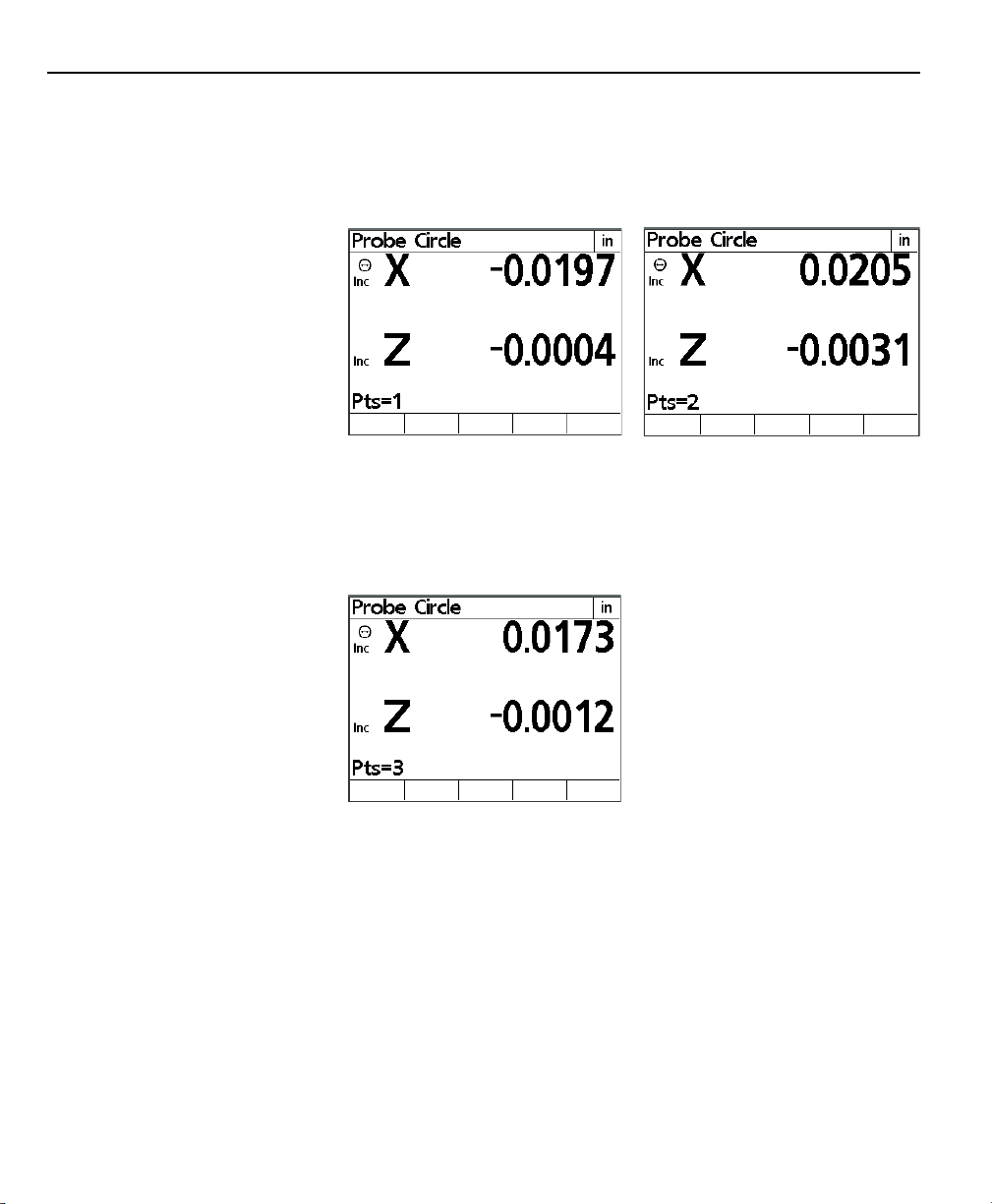
Step 2
Align the tool with the crosshairs on the tool presetter and press
enter. The location of the targeted point will be shown on the
Probe Circle screen and the number of points indicated on the
lower left part of the display will increase.
Step 3
Align the tool with the crosshairs on the tool presetter on the
second point and press enter. The new location will be shown
and the number of points will increase again. The Tool-Chek requires a minimum of 3 points to measure a circle.
2-20
Page 47

Tool-Chek® TC200
Step 4
Continue this process until all of the points have been targeted
and entered. When all of the required points on the perimeter of
the circle have been entered, press the Finish key.
Step 5
Press the Tool feature selection key. Enter the tool information
and press the save softkey.
2-21
Page 48

Chapter 2 Operation
Measuring an angle
Angles can be measured by targeting between 2 and 100 points
on each of the vertices of the angle. Generally, accuracy of the
feature is increased as more points are targeted and the targeted
points are distributed at more or less equal distances along the
line.
NOTENOTE
NOTE
NOTENOTE
The procedure below assumes that angle data is required for aThe procedure below assumes that angle data is required for a
The procedure below assumes that angle data is required for a
The procedure below assumes that angle data is required for aThe procedure below assumes that angle data is required for a
saved tool. If angle data is required for simple verification orsaved tool. If angle data is required for simple verification or
saved tool. If angle data is required for simple verification or
saved tool. If angle data is required for simple verification orsaved tool. If angle data is required for simple verification or
other purposes, press the angle feature selection key and proceedother purposes, press the angle feature selection key and proceed
other purposes, press the angle feature selection key and proceed
other purposes, press the angle feature selection key and proceedother purposes, press the angle feature selection key and proceed
from step 2.from step 2.
from step 2.
from step 2.from step 2.
To measure an angle
Step 1
Press the Angle feature selection key. Be certain there is not a
tool selected. If a tool name appears at the top of the screen
press the Quit command key followed by Angle feature selection
key. The Probe Line 1 screen will be displayed.
2-22
Page 49

Tool-Chek® TC200
Step 2
Align the first line of the angle with the crosshairs on the tool
presetter and press enter. The location of the targeted point will
be shown on the Probe Line 1 screen and the number of points
indicated on the lower left part of the display will increase. A
minimum of 2 points is needed for a line. When all points are
entered press the Finish command key.
Step 3
Align the second line of the angle with the crosshairs on the tool
presetter and press enter. The location of the targeted point will
be shown on the Probe Line 2 screen and the number of points
indicated on the lower left part of the display will increase. A
minimum of 2 points is needed for a line. When all points are
entered press the Finish command key.
2-23
Page 50

Chapter 2 Operation
Step 4
Press the Tool feature selection key. Enter the tool information
and press the save softkey.
2-24
Page 51

Tool-Chek® TC200
Zeroing Axes
Press the zero key to zero one or both axes on the TC200. The
TC200 will prompt: press axis to zero, or press zero again to zero
both axes.
Freezing Axes
Occasionally a tool is to large to fit entirely on the tool presetter.
When this happens it is sometimes necessary to measure one axis
at a time. The TC200 allows users to freeze axes in order to measure along only one axis at a time.
To freeze an axis, press the freeze/zero axis key adjacent the axis
to be froze. In this example the X axis is frozen. When an axis is
frozen it appears in a hollow font.
2-25
Page 52

Chapter 2 Operation
2-26
Page 53

Configuring the TC200
Basic setup terms
Chapter 3
Setup
Configure the TC200 prior to using it the first time and when tool
measurement, reporting, or data communication requirements
change. System configurations are entered using the arrow keys,
command keys, softkeys, and numeric keypad. The setup menu
structure allows easy navigation and quick setup of the TC200.
The following is a list of terms used in this chapter and their definitions.
Data entry field: Any item within a setup screen that requires
numeric input from the user. The MM Disp
Res field on the Display setup screen is a
data entry field.
Highlight: Placing the cursor block on a particular item
in a list or data entry field.
Option
selection field: Any item within a setup screen that can be
changed by selecting options using the
softkeys. The English field on the About
setup screen is an option selection field.
Scroll: Using the up or down arrow keys to move
the cursor block (highlight) through a list.
Setup screen: Any screen accessed via the setup softkey.
The About setup screen is the first screen
displayed after pressing the Setup softkey.
Additional setup screens can be accessed by
scrolling through the list with the up or
down arrow keys.
4-1
Page 54

Chapter 3 Setup
The Setup Menu
Accessing the
Setup menu
All operating parameters of the TC200 can be configured using
functions in the Setup menu. These parameters include:
• Language shown on the LCD display
• Display format of tool data
• Encoder configuration
• Print configuration for reports and labels
• Ports configuration for serial and parallel
• Supervisor password
• Squareness angle
• LEC (Linear Error Correction)
• SLEC (Segmented Linear Error Correction) configuration
• Scale factor
• Misc (Miscellaneous) parameters
• Clock date and time settings
Setup configurations are retained by the TC200 until changed by
the user.
The Setup menu is accessed by pressing the Menu key and then
pressing the Setup softkey. Setup menu procedures are divided
into user level procedures and supervisor level procedures. Supervisor level procedures require the input of the supervisor password in the Supervisor setup screen. If the supervisor password
has not been entered, all supervisor level procedures are inaccessible. The supervisor password is not retained through power
cycles; it must be re-entered each time the unit is turned off and
on.
3-2
The Setup menu contents are displayed on the left side of the
screen with the About setup screen highlighted.
Page 55

Using the
Setup menu
Setup Instructions
Tool-Chek® TC200
To select from the Setup menu scroll through the list using the up
or down arrow keys and highlight the desired setup screen. When
a setup screen is highlighted, associated data entry fields and option selection fields appear on the right portion of the screen and
can be configured or changed using arrow keys, softkeys, command keys, and numeric keypad.
Selecting and configuring system parameters are explained in the
Using the Setup menu section of this chapter. Configure the TC200
prior to using it the first time and when tool measurement, reporting, or data communication requirements change.
To access the setup menu, press the menu key and then press the
setup softkey.
3-3
Page 56

Chapter 3 Setup
Command Keys
The enter, finish, cancel and quit keys have slightly different functions during setup activities.
Enter Key
Press the enter key to store the highlighted value or selection and
advance to the next setup parameter. Pressing enter at the bottom of a list advances to the top of the list.
Finish Key
Press the finish key to store all parameters for the current setup
activity and return to the setup menu.
Cancel Key
Press the cancel key to erase the last digit in a highlighted data
field.
3-4
Quit Key
Pressing the quit key to store all parameters for the current setup
activity and return to the setup menu.
Page 57

Supervisor Password
Tool-Chek® TC200
Most setup functions are password protected. Users with supervisor access have unrestricted access to setup screen activities. Only
users with extensive tool presetter and TC200 experience should
perform supervisor level setup procedures. The supervisor password is contained in the TC200 packing materials and is clearly
labeled.
To enter the password
Step 1
Scroll through the setup menu until Supervisor is highlighted.
Step 2
Press the left cursor arrow to highlight the password data entry
field. Use the numeric keypad to enter the password, then press
enter.
Press the left arrow key to return to the setup menu.
3-5
Page 58

Chapter 3 Setup
About
The About setup screen allows the user to change the default
display language. Users may choose English, French, German,
Spanish, or Italian. This screen also contains software version information. All procedures on this screen are user level.
Scroll through the setup menu using the up or down arrow keys
until About is highlighted.
Press the right arrow key to highlight items in the right portion of
the screen. Press the up or down arrow key or enter to scroll
through the languages. Highlight the desired language and press
the yes softkey. Press the left arrow key or finish to save the
language selection and return to the setup menu.
Display
3-6
The display setup screen contains 4 user level procedures and 4
supervisor level procedures. Users can change the startup units of
linear and angular measurement, select decimal or comma radices, and designate angular measurement format. Supervisors can
input display resolutions for millimeters, inches, decimal degrees;
and degrees, minutes, and seconds in addition to the above user
level procedures.
Page 59

Tool-Chek® TC200
Display resolution determines the number of decimal places the
TC200 will display. For example, if the millimeter display resolution
is set to .1, the TC200 will display a measurement of 1.2311 millimeters as 1.2. Any value up to the resolution of the encoder can
be entered for display resolution. Values in excess of the encoder
resolution result in accurate display information.
NOTENOTE
NOTE
NOTENOTE
When inputting resolution remember that .0001mm is a higherWhen inputting resolution remember that .0001mm is a higher
When inputting resolution remember that .0001mm is a higher
When inputting resolution remember that .0001mm is a higherWhen inputting resolution remember that .0001mm is a higher
resolution than .0002mm. Therefore, any entry less thanresolution than .0002mm. Therefore, any entry less than
resolution than .0002mm. Therefore, any entry less than
resolution than .0002mm. Therefore, any entry less thanresolution than .0002mm. Therefore, any entry less than
.0002mm exceeds the resolution of an encoder with .0002mm.0002mm exceeds the resolution of an encoder with .0002mm
.0002mm exceeds the resolution of an encoder with .0002mm
.0002mm exceeds the resolution of an encoder with .0002mm.0002mm exceeds the resolution of an encoder with .0002mm
resolution.resolution.
resolution.
resolution.resolution.
Scroll through the setup menu until Display is highlighted.
The following data entry fields are displayed, MM Disp Res (millimeter display resolution), Inch Disp Res (inch display resolution),
DMS Disp Res (degrees, minutes, seconds display resolution), DD
Disp Res (decimal degrees display resolution). Each of these fields
are supervisor level procedures and require the supervisor password to be entered prior to changing.
The following option selection fields are displayed, Startup Linear,
Startup Angular, Radix, and Current Angular. Each of these fields
are user level procedures and can be changed without entering
the supervisor password.
Press the right cursor key to select items in the right portion of
the screen.
3-7
Page 60

Chapter 3 Setup
MM Disp Res
Defines the measurement resolution displayed on the TC200 for
linear information in mm (metric) mode. Any resolution at or
below the resolution of the encoder is a valid entry for this field.
Do not enter a resolution higher than the encoder resolution.
Consult the encoder product information to determine its resolution. This data entry field requires the supervisor password prior
to access.
NOTENOTE
NOTE
NOTENOTE
When inputting resolution remember that .0001mm is a higherWhen inputting resolution remember that .0001mm is a higher
When inputting resolution remember that .0001mm is a higher
When inputting resolution remember that .0001mm is a higherWhen inputting resolution remember that .0001mm is a higher
resolution than .0002mm. Therefore, any entry less thanresolution than .0002mm. Therefore, any entry less than
resolution than .0002mm. Therefore, any entry less than
resolution than .0002mm. Therefore, any entry less thanresolution than .0002mm. Therefore, any entry less than
.0002mm exceeds the resolution of an encoder with .0002mm.0002mm exceeds the resolution of an encoder with .0002mm
.0002mm exceeds the resolution of an encoder with .0002mm
.0002mm exceeds the resolution of an encoder with .0002mm.0002mm exceeds the resolution of an encoder with .0002mm
resolution.resolution.
resolution.
resolution.resolution.
3-8
Inch Disp Res
Defines the measurement resolution displayed on the TC200 for
linear information in inch (English) mode. Any resolution at or
below the resolution of the encoder is a valid entry for this field.
Do not enter a resolution higher than the encoder resolution.
Consult the encoder product information to determine its resolution. This data entry field requires the supervisor password prior
to access.
Page 61

Tool-Chek® TC200
NOTENOTE
NOTE
NOTENOTE
When inputting resolution remember that .0001in is a higherWhen inputting resolution remember that .0001in is a higher
When inputting resolution remember that .0001in is a higher
When inputting resolution remember that .0001in is a higherWhen inputting resolution remember that .0001in is a higher
resolution than .0002in. Therefore, any entry less than .0002inresolution than .0002in. Therefore, any entry less than .0002in
resolution than .0002in. Therefore, any entry less than .0002in
resolution than .0002in. Therefore, any entry less than .0002inresolution than .0002in. Therefore, any entry less than .0002in
exceeds the resolution of an encoder with .0002in resolution.exceeds the resolution of an encoder with .0002in resolution.
exceeds the resolution of an encoder with .0002in resolution.
exceeds the resolution of an encoder with .0002in resolution.exceeds the resolution of an encoder with .0002in resolution.
DMS Disp Res
Defines the measurement resolution displayed on the TC200 for
angular information in degree, minute, and second format. Any
resolution at or below the resolution of the encoder is a valid
entry for this field. Do not enter a resolution higher than the
encoder resolution. Consult the encoder product information to
determine its resolution. This data entry field requires the supervisor password prior to access.
NOTENOTE
NOTE
NOTENOTE
When inputting resolution remember that .0001mm is a higherWhen inputting resolution remember that .0001mm is a higher
When inputting resolution remember that .0001mm is a higher
When inputting resolution remember that .0001mm is a higherWhen inputting resolution remember that .0001mm is a higher
resolution than .0002mm. Therefore, any entry less thanresolution than .0002mm. Therefore, any entry less than
resolution than .0002mm. Therefore, any entry less than
resolution than .0002mm. Therefore, any entry less thanresolution than .0002mm. Therefore, any entry less than
.0002mm exceeds the resolution of an encoder with .0002mm.0002mm exceeds the resolution of an encoder with .0002mm
.0002mm exceeds the resolution of an encoder with .0002mm
.0002mm exceeds the resolution of an encoder with .0002mm.0002mm exceeds the resolution of an encoder with .0002mm
resolution.resolution.
resolution.
resolution.resolution.
3-9
Page 62

Chapter 3 Setup
DD Disp Res
Defines the measurement resolution displayed on the TC200 for
angular information in decimal degree format. Any resolution at
or below the resolution of the encoder is a valid entry for this
field. Do not enter a resolution higher than the encoder resolution. Consult the encoder product information to determine its
resolution. This data entry field requires the supervisor password
prior to access.
NOTENOTE
NOTE
NOTENOTE
When inputting resolution remember that .0001mm is a higherWhen inputting resolution remember that .0001mm is a higher
When inputting resolution remember that .0001mm is a higher
When inputting resolution remember that .0001mm is a higherWhen inputting resolution remember that .0001mm is a higher
resolution than .0002mm. Therefore, any entry less thanresolution than .0002mm. Therefore, any entry less than
resolution than .0002mm. Therefore, any entry less than
resolution than .0002mm. Therefore, any entry less thanresolution than .0002mm. Therefore, any entry less than
.0002mm exceeds the resolution of an encoder with .0002mm.0002mm exceeds the resolution of an encoder with .0002mm
.0002mm exceeds the resolution of an encoder with .0002mm
.0002mm exceeds the resolution of an encoder with .0002mm.0002mm exceeds the resolution of an encoder with .0002mm
resolution.resolution.
resolution.
resolution.resolution.
3-10
Startup Linear
Defines the default display of linear measurements. Options for
this field include MM (metric/millimeters), Inch (English/decimal
inches), and Last. The Last option will retain the last selection
made via the mm mode selection key through power cycles. For
example, if inches was the last unit selected with the mm key prior
to shutdown, the TC200 will startup in inches for its next use.
Selections for this field are made using softkeys.
Page 63

Tool-Chek® TC200
Startup Angular
Defines the default display of angular measurements. Options for
this field include DD (decimal degrees), DMS (degrees, minutes,
and seconds), and Last. The Last option will retain the last selection through power cycles. For example, if decimal degrees was
the last unit selected prior to shutdown, the TC200 will startup in
decimal degrees for its next use. Selections for this field are made
using softkeys.
Radix
Radix settings are available for English (dot: 1.000) or European
(comma: 1,000) presentations. Selections for this field are made
using softkeys.
3-11
Page 64

Chapter 3 Setup
Encoders
Current Angular
Defines the default display of measured angles until the TC200 is
shutdown. At the next startup, the Startup Angular setting defines the default display of measured angles. Options for this
field include DD (decimal degrees) and DMS (degrees, minutes,
and seconds). Selections for this field are made using softkeys.
Press the left arrow key or finish to return to the setup menu. Use
the up or down arrow keys to scroll through the setup menu and
highlight Encoders.
3-12
The encoder setup screen contains 1 user level procedures and 7
supervisor level procedures. Users can observe the encoder setup
for the X and Z axes. Supervisors can input encoder resolution,
define encoder type, select reference marks, obtain machine zero,
reverse axis direction, enter interpolation values, and select units
of measure.
Press the right arrow key to select items in the right portion of the
screen.
Page 65

Tool-Chek® TC200
Axis
Users can toggle between the X and Z axes using softkeys to observe encoder settings. Supervisors can use the softkeys to select
an axis to configure.
Resolution (Res)
Enter the encoder resolution using the numeric keypad. Consult
the encoder product information to determine its resolution.
Entries in this field must precisely match the encoder resolution.
This data entry field requires the supervisor password prior to
access.
3-13
Page 66
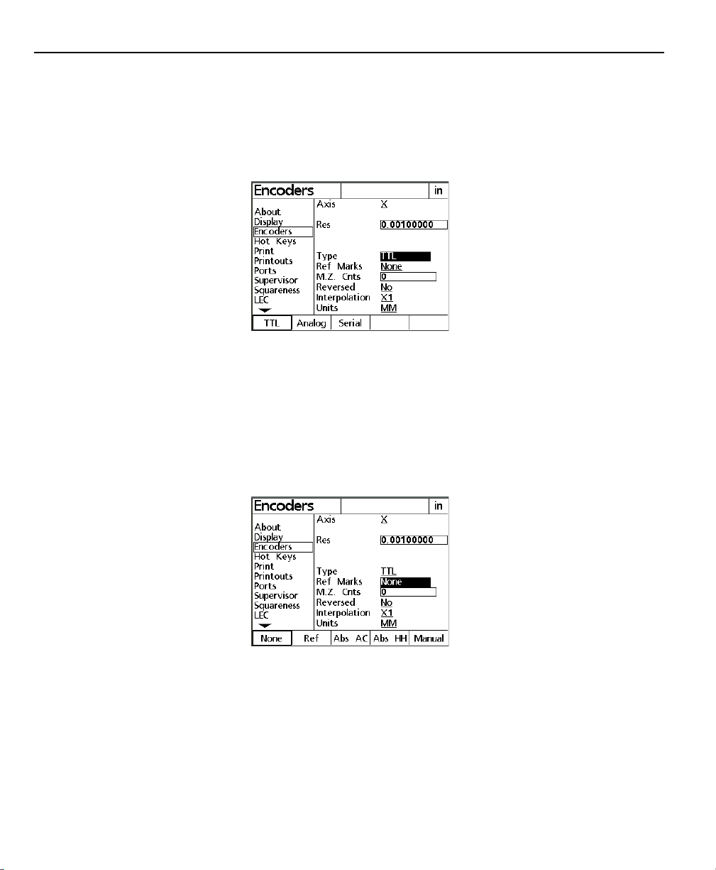
Chapter 3 Setup
Type
Use the softkeys to select the encoder type. The following encoder types are supported on the TC200: TTL, analog, and serial.
Consult the encoder product information to determine its type.
This option selection field requires the supervisor password prior
to access.
Reference Marks
Encoder reference marks are used for Segmented Linear Error
Correction (SLEC). Use the softkeys to select from the following
options: none, ref, abs AC (absolute Acu-Rite), abs HH (absolute
Heidenhain), and manual. The TC200 prompts the user to move
each axis encoder across a reference mark prior to measurement
activities when reference marks are used. This option selection
field requires the supervisor password prior to access.
3-14
Page 67

Tool-Chek® TC200
MZ Cnts
Allows the user to define the machine zero position of an encoder by moving it to the desired position.
Entering a zero in this field causes the TC200 to automatically
record the current position of the encoder as the machine zero at
the next startup. Subsequent startups will not change the machine zero unless this field is reset to zero first. This data entry
field requires the supervisor password prior to access.
Reversed
The normal convention for the display of the polarity of measurements is:
• Motion to the right is positive (X axis)
• Motion up is positive (Z axis)
The settings for any axis can be reversed to accommodate the
encoder mounting requirements of the system used. Press the No
softkey to retain the positive polarity for the selected axis, or press
the Yes softkey to achieve the correct polarity for different encoder mounting. Press the down cursor arrow or Enter key to
advance the display and highlight Interpolation. This option selection field requires the supervisor password prior to access.
3-15
Page 68

Chapter 3 Setup
NOTENOTE
NOTE
NOTENOTE
When presetting lathe tools this option selection field can beWhen presetting lathe tools this option selection field can be
When presetting lathe tools this option selection field can be
When presetting lathe tools this option selection field can beWhen presetting lathe tools this option selection field can be
used to compensate for tools with a down and/orused to compensate for tools with a down and/or
used to compensate for tools with a down and/or
used to compensate for tools with a down and/orused to compensate for tools with a down and/or
left-hand cutting direction. For example when presetting a lathleft-hand cutting direction. For example when presetting a lath
left-hand cutting direction. For example when presetting a lath
left-hand cutting direction. For example when presetting a lathleft-hand cutting direction. For example when presetting a lath
tool with a cut direction of down and left, reverse both the Xtool with a cut direction of down and left, reverse both the X
tool with a cut direction of down and left, reverse both the X
tool with a cut direction of down and left, reverse both the Xtool with a cut direction of down and left, reverse both the X
and Z axes to obtain positive numbers during presetting.and Z axes to obtain positive numbers during presetting.
and Z axes to obtain positive numbers during presetting.
and Z axes to obtain positive numbers during presetting.and Z axes to obtain positive numbers during presetting.
Interpolation
Press the softkey interpolation value required for the encoder
being used on the selected axis and press the down cursor arrow
or Enter key to advance the display and highlight Units. This
option selection field requires the supervisor password prior to
access.
3-16
Units
Enter the encoder units using the softkeys. Users can select In
(inches), MM (millimeters), and Deg (degrees). Consult the encoder product information to determine the proper unit. Entries
in this field must precisely match the encoder unit. This option
selection field requires the supervisor password prior to access.
Press the left arrow key or finish to return to the setup menu.
Scroll through the Setup menu until the Print selection is highlighted.
Page 69

Tool-Chek® TC200
The print setup screen contains 4 user level procedures and 8 supervisor level procedures.
Users can insert ASCII control character for pre line, post line, pre
form, and post form operations. Typically these character insertions are for line feeds are carriage returns. A chart of common
ASCII characters can be found in Chapter 3: Communications and
at the end of this section.
Supervisor can set reports and labels to print, set tool location
and position of tool to print, define number of lines per label, set
number of skipped lines, and set label indents.
Press the right cursor arrow to select items in the right portion of
the screen.
Auto Label
When yes is selected in this field labels automatically print after
the finish key is pressed on the new tool or edit tool screens. This
option selection field requires the supervisor password to be entered prior to access.
3-17
Page 70

Chapter 3 Setup
Auto Report
When yes is selected in this field tool sequence reports are automatically printed at the end of a tool sequence run. If no is selected the TC200 will prompt the user ‘Print tool sequence report?’ This option selection field requires the supervisor password to be entered prior to access.
Label Format
Press the list softkey to access the format list. Use the up or down
arrow keys to select a report format. Press finish to return to the
label format setup screen. This option selection field requires the
supervisor password to be entered prior to access.
3-18
Page 71

Tool-Chek® TC200
Pre Line
To add an output control character before a line is printed use
the numeric keypad to enter an ASCII control character in this
field.
Post Line
To add an output control character after a line is printed use the
numeric keypad to enter an ASCII control character in this field.
Pre Form
To add an output control character before a form is printed use
the numeric keypad to enter an ASCII control character in this
field.
3-19
Page 72

Chapter 3 Setup
Post Form
To add an output control character after a form is printed use the
numeric keypad to enter an ASCII control character in this field.
Print Report
Enables or disables tool sequence report print function. Use the
softkeys to select yes or no. This option selection field requires
the supervisor password prior to access.
3-20
Label Lines
Use the numeric keypad to enter the desired number of lines for
labels. This data entry field requires the supervisor password prior
to access.
Page 73

Tool-Chek® TC200
Skip Lines
Use the numeric keypad to enter the number of lines skipped
between printed lines. This data entry field requires the supervisor password prior to access.
Label Indent
Use the numeric keypad to enter the number of indent spaces for
labels. This data entry field requires the supervisor password prior
to access.
3-21
Page 74

Chapter 3 Setup
3-22
Scroll through the setup menu to highlight Ports.
Page 75

Ports
Tool-Chek® TC200
Serial (RS232) communications are configured on this screen. Parallel port protocols are standard and require no end-user setup.
In order to connect the TC200 to a serial printer setting on this
page must match the corresponding parameter of the printer.
Consult the printer information for its operating parameters.
NOTENOTE
NOTE
NOTENOTE
Metronics attempts to support the widest variety of printersMetronics attempts to support the widest variety of printers
Metronics attempts to support the widest variety of printers
Metronics attempts to support the widest variety of printersMetronics attempts to support the widest variety of printers
available. Still, not every serial printer is compatible with theavailable. Still, not every serial printer is compatible with the
available. Still, not every serial printer is compatible with the
available. Still, not every serial printer is compatible with theavailable. Still, not every serial printer is compatible with the
TC200. Carefully check the ports setup for accuracy if the printerTC200. Carefully check the ports setup for accuracy if the printer
TC200. Carefully check the ports setup for accuracy if the printer
TC200. Carefully check the ports setup for accuracy if the printerTC200. Carefully check the ports setup for accuracy if the printer
fails to work. If all settings appear correct the printer may notfails to work. If all settings appear correct the printer may not
fails to work. If all settings appear correct the printer may not
fails to work. If all settings appear correct the printer may notfails to work. If all settings appear correct the printer may not
be compatible.be compatible.
be compatible.
be compatible.be compatible.
The print setup screen contains 9 supervisor level procedures. There
are no user level procedures on this setup screen. All fields require the supervisor password prior to access.
Supervisors can set baud rate (Baud), word length (Word Len),
stop bits, parity, handshake, data, parallel data protocols, end of
character delay (EOC Delay), and end of line delay (EOL Delay).
3-23
Page 76

Chapter 3 Setup
Baud
The RS232 baud rate can be increased or decreased by pressing
the Dec or Inc softkeys. The available baud rates are 1200; 2400;
4800; 9600; 19,200; 38,400; 57,600; and 115,200. This option selection field requires the supervisor password prior to access.
Word Len (word length)
Press the softkeys to select 7 or 8 bit word length. This option
selection field requires the supervisor password prior to access.
3-24
Stop Bits
Press the softkeys to select 1 or 2 stop bits. This option selection
field requires the supervisor password prior to access.
Page 77

Tool-Chek® TC200
Parity
Press the softkeys to select none, odd, or even parity. This option
selection field requires the supervisor password prior to access.
Handshake
Press the softkeys to select the proper handshake protocol. This
option selection field requires the supervisor password prior to
access.
3-25
Page 78

Chapter 3 Setup
Data/ Parallel Data
Reports of measurement data can be sent to the serial or parallel
port for printing. There are four softkey options for this field:
none, display, report, and both. Press the none softkey if no
printed reports are required. Press the display softkey to view
reports on the LCD display. Press the report softkey to print all
reports. Press the both softkey to display reports on the LCD and
print. This option selection field requires the supervisor password
prior to access. This option selection field requires the supervisor
password prior to access.
EOC Delay (end of character delay)
Use the numeric keypad to enter values up to 10,000 (1 second).
This setting determines the printer delay between printed characters. This data entry field requires the supervisor password prior
to access.
3-26
Page 79

Tool-Chek® TC200
EOL Delay (end of line delay)
Use the numeric keypad to enter values up to 1,000,000 (1 minute).
This setting determines the printer delay between printed lines.
This data entry field requires the supervisor password prior to
access.
NOTENOTE
NOTE
NOTENOTE
Occasionally the data exchange rate between the TC200 and aOccasionally the data exchange rate between the TC200 and a
Occasionally the data exchange rate between the TC200 and a
Occasionally the data exchange rate between the TC200 and aOccasionally the data exchange rate between the TC200 and a
printer can exceed the printer’s capabilities. If printing problemsprinter can exceed the printer’s capabilities. If printing problems
printer can exceed the printer’s capabilities. If printing problems
printer can exceed the printer’s capabilities. If printing problemsprinter can exceed the printer’s capabilities. If printing problems
occur after printing has begun, set the EOC delay and EOL delayoccur after printing has begun, set the EOC delay and EOL delay
occur after printing has begun, set the EOC delay and EOL delay
occur after printing has begun, set the EOC delay and EOL delayoccur after printing has begun, set the EOC delay and EOL delay
to the maximum values. If this eliminates the problem,to the maximum values. If this eliminates the problem,
to the maximum values. If this eliminates the problem,
to the maximum values. If this eliminates the problem,to the maximum values. If this eliminates the problem,
experiment with lower settings to find the fastest workingexperiment with lower settings to find the fastest working
experiment with lower settings to find the fastest working
experiment with lower settings to find the fastest workingexperiment with lower settings to find the fastest working
settings. Remembersettings. Remember
settings. Remember
settings. Remembersettings. Remember
1 second delay after each character and a 1 minute delay after1 second delay after each character and a 1 minute delay after
1 second delay after each character and a 1 minute delay after
1 second delay after each character and a 1 minute delay after1 second delay after each character and a 1 minute delay after
each line.each line.
each line.
each line.each line.
, the maximum EOC and EOL delay insert a, the maximum EOC and EOL delay insert a
, the maximum EOC and EOL delay insert a
, the maximum EOC and EOL delay insert a, the maximum EOC and EOL delay insert a
Scroll through the Setup menu to highlight Squareness.
3-27
Page 80

Chapter 3 Setup
Squareness
The squareness correction coefficient is used to compensate for
small machine errors that can exist between the X and Z measurement axes.
Angle
Press the teach softkey. Measure a line along the master axis.
Press enter to input a point. Lines require at least two points.
Press finish. This data entry field requires the supervisor password
prior to access.
3-28
Page 81

Tool-Chek® TC200
Master Axis
Press the X or Z softkey to designate the master axis. This option
selection field requires the supervisor password prior to access.
Press the left arrow key or finish to return to the setup menu.
3-29
Page 82

Chapter 3 Setup
Error Correction
Linear, segmented linear and non-linear error correction methods
can be used with the TC200. Linear and segmented linear error
corrections are provided with every TC200. system and non-linear
error correction is provided as an option. Each method compensates for encoder and machine travel variations using error correction coefficients developed by comparing actual measurements
of a standard to the standard’s nominal values.
Linear error correction (LEC) uses one correction coefficient for
each axis to compensate for variations along the axis. For example, a linear error correction coefficient of 0.0002 “/inch applied to a 6” measurement along the X axis would produce a measurement result of 6.0012”.
Segmented linear error correction (SLEC) divides each axis into up
to 7 segments. Each segment uses one error correction coefficient to compensate for variations within the segment. Each axis
also includes a machine zero offset to refer the position of the
standard’s datum to the machine zero reference. The standard’s
nominal and measured segment values must be specified during
the setup process. The machine zero offset for each axis must
also be specified. When SLEC is used, the stage must be moved to
cross a reference mark/hard-stop on each axis upon system startup
to initialize SLEC.
3-30
Non-linear error correction (NLEC) uses a standard that divides the
entire measurement area into a grid of up to 30 X 30 cells. Each
cell uses error correction coefficient for each axis to compensate
for variations within a cell. The standard’s nominal and measured
X and Y values must be specified for the positions of each cell
during the setup process. The machine zero offset to the grid
datum must also be specified. When NLEC is used, the stage must
have a repeatable machine zero defined on startup to initialize NLEC.
NOTENOTE
NOTE
NOTENOTE
YY
ou must set the machine zero by crossing reference marks onou must set the machine zero by crossing reference marks on
Y
ou must set the machine zero by crossing reference marks on
YY
ou must set the machine zero by crossing reference marks onou must set the machine zero by crossing reference marks on
the X and Y encoders before calibrating the SLEC and NLEC errorthe X and Y encoders before calibrating the SLEC and NLEC error
the X and Y encoders before calibrating the SLEC and NLEC error
the X and Y encoders before calibrating the SLEC and NLEC errorthe X and Y encoders before calibrating the SLEC and NLEC error
corrections.corrections.
corrections.
corrections.corrections.
Page 83

Linear Error Correction (LEC)
Tool-Chek® TC200
Scroll through the Setup menu to highlight Linear Error Correction (LEC). Linear error correction coefficients are used to compensate for overall encoder and machine travel variations. A standard is measured, and the measured value is compared to the
known value of the standard to generate the correction coefficient. Correction coefficients are generated for each axis and
used in subsequent measurements to provide linear compensation for encoder variations.
Press the right arrow key to select items in the right portion of
the screen.
Enter the nominal value of the standard for each axis into the
appropriate Standard data field using the numeric keypad on the
front panel. Use the down cursor arrow to scroll to the desired
data field.
3-31
Page 84

Chapter 3 Setup
Measure the standard on each axis and enter the measured value
into the appropriate Observed data field using the numeric keypad on the front panel. Use the down cursor arrow to scroll to
the desired data field.
When all the nominal and observed data is entered, press the left
cursor arrow or Finish button to return to the Setup menu.
3-32
Page 85

Segmented Linear Error Correction (SLEC)
Tool-Chek® TC200
Scroll through the Setup menu to highlight Segmented Linear
Error Correction (SLEC). Linear error correction coefficients are
applied to segments of each axis to compensate for encoder and
machine travel variations. The standard is measured on each axis,
and the measured values are compared to the nominal values to
generate correction coefficients. Correction coefficients are generated for each segment that deviates from the nominal value.
The correction coefficients are then used to provide linear compensation for only the segments requiring it.
Mount the standard on the stage and zero axes on the datum of
the standard. Measure and graph the nominal and actual segment values as shown below. A segment is any group of points
that combine to form a straight line.
NOTENOTE
NOTE
NOTENOTE
The numbers used in this example are only meant to illustrateThe numbers used in this example are only meant to illustrate
The numbers used in this example are only meant to illustrate
The numbers used in this example are only meant to illustrateThe numbers used in this example are only meant to illustrate
the process and are not intended to suggest actual values.the process and are not intended to suggest actual values.
the process and are not intended to suggest actual values.
the process and are not intended to suggest actual values.the process and are not intended to suggest actual values.
3-33
Page 86

Chapter 3 Setup
Nominal (Standard)
Actual (Measured)
3-34
Select the desired axis and enter the nominal and actual end points
of each segment into the SLEC Standard and Observed data fields
as shown below. A maximum of 30 segments (0-29) can be entered (7 are shown in this example).
Enter the offset from the Machine zero to the standard’s datum
for the current axis into the MZ Offset data field.
Press the ON softkey to use SLEC compensation for the selected
axis.
When all the data are entered for all axes, press the left cursor
arrow or Finish button to return to the Setup menu.
Page 87

Misc. (miscellaneous)
Libraries
Tool-Chek® TC200
The miscellaneous setup screen contains 1 supervisor level function and 1 user level function. The two data entry fields contained on this screen are: key delay and volume.
Key Delay
This data entry field allows supervisor level users to set the interval
an arrow key must be depressed prior to executing its function a
second time. Use this field to adjust the keys for rapid or slow
scrolling through TC200 lists and to account for operator dexterity. This data entry field requires the supervisor password to be
entered prior to access.
Volume
This data entry field allows users to increase or decrease the volume of the TC200 sounds. 1 through 10 are valid inputs in this
field (the TC200 does not go to 11).
The libraries setup screen contains 5 supervisor level functions.
The five option selection fields on this screen are as follows: use
locations, tool button, SG 00 master, SG edit lock, and SG cal loc.
All fields require the supervisor password to be entered prior to
access.
3-35
Page 88

Chapter 3 Setup
Use Locations
This option selection field enables the Tool Loc field found on the
tool setup screen. Press the yes softkey to enable this function or
the no softkey to disable it. This option selection field requires
the supervisor password to be entered prior to access.
3-36
Tool Button
This option selection field determines the navigation result when
the tool key is pressed. Press the new softkey to bring up the new
Tool setup screen when the tool key is pressed. Press the select
softkey to bring up the select tool screen when the tool key is
pressed. This option selection field requires the supervisor password to be entered prior to access.
Page 89

Tool-Chek® TC200
SG 00 master
The options selection field assigns all calibrations relative to a master setting gage rather than absolute or machine zero. Press the
yes softkey to enable this function. Press the no softkey to calibrate each setting individually against absolute/machine zero. This
option selection field requires the supervisor password to be entered prior to access.
SG Edit Lock
The options selection field allows setting gage edit options to be
enabled or disabled. Press the yes softkey to allow edits to setting
gages. Press the no softkey to prevent edits to setting gages.
This option selection field requires the supervisor password to be
entered prior to access.
3-37
Page 90

Chapter 3 Setup
SG Cal Lock
The options selection field allows setting gage calibration to be a
supervisor level function. This will prevent users from inadvertently altering calibrations. Press the yes softkey to allow this
function. Press the no softkey to disable it. This option selection
field requires the supervisor password to be entered prior to access.
3-38
Tool Sequence Edit Lock
This option selection field allows supervisor level users to make
tool sequence editing a supervisor level or user level function.
Press the yes softkey to make tool sequence editing a supervisor
level function or the no softkey to make it a user level function.
This option selection field requires the supervisor password prior
to access.
Page 91

Clock
Tool-Chek® TC200
The clock setup screen contains 8 supervisor level functions. The 6
data entry fields and 2 option selection fields are as follows: year,
month, day, hours, minutes, seconds, date format, time format.
All fields require the supervisor password to be entered prior to
access.
Year
Enter the current year in this data entry field by using the numeric
keypad. This data entry field requires the supervisor password to
be entered prior to access.
3-39
Page 92

Chapter 3 Setup
Month
Enter the current month in this data entry field by using the numeric keypad. This data entry field requires the supervisor password to be entered prior to access.
3-40
Day
Enter the current day in this data entry field by using the numeric
keypad. This data entry field requires the supervisor password to
be entered prior to access.
Hours
Enter the current hour using the numeric keypad. This data entry
field requires the supervisor password to be entered prior to access.
Page 93

Tool-Chek® TC200
Minutes
Enter the current minute using the numeric keypad . This data
entry field requires the supervisor password to be entered prior
to access.
Seconds
Enter the current second using the numeric keypad. This data
entry field requires the supervisor password prior to access.
Date Format
Use the softkeys to select month/day/year or day/month/year format. This option selection field requires the supervisor password
to be entered prior to access.
3-41
Page 94

Chapter 3 Setup
Time Format
Use the softkeys to select a 12 hour clock or a 24 hour clock. This
option selection field requires the supervisor password to be entered prior to access.
3-42
Page 95

RS232 port
Chapter 4
Communications
This chapter explains how to establish the interface between a
printer or computer and the TC200. There are many manufacturers of printers, and unfortunately not all printers are compatible.
It would be impossible to support all of them. Parallel printers
must support the Text Only mode.
NOTENOTE
NOTE
NOTENOTE
It is the users responsibility to check printer compatibilityIt is the users responsibility to check printer compatibility
It is the users responsibility to check printer compatibility
It is the users responsibility to check printer compatibilityIt is the users responsibility to check printer compatibility
cabling and system configuration accordinglycabling and system configuration accordingly
cabling and system configuration accordingly
cabling and system configuration accordinglycabling and system configuration accordingly
The RS232 port must be configured to communicate with your
printer or computer.
..
.
..
,,
,
,,
3-1
Page 96

Chapter 4 Communications
Default settings
Ports section of Setup menu:
The following is a list of factory default settings.
• Baud Rate: 38400
• Word Length: 8
• Stop Bits: 1
• Parity: Odd
• Handshake: Hard
• Data Bits: None
• Parallel Data: Display
Print section of Setup menu:
Pre Line: Enter ASCII control character (string) for printer
control before printing a line.
Post Line: Enter ASCII control character (string) for printer
control after printing a line.
Pre Form: Enter ASCII control character (string) for printer
control before printing a form.
Post Form: Enter ASCII control character (string) for printer
control after printing a form.
4-2
Page 97

Tool-Chek® TC200
Feature print formats
In the following, the “v” means to ignore the character it is substituted for i.e., X, Y, Z, r, d, <, T, R, A, etc.
“d” means digit
“-” is the negative sign
“s” means space
“c” means carriage return
4-3
Page 98

Chapter 4 Communications
Feature Formats
Print Setup
For positive outputs, the space character will be substituted for
the negative sign “-”. The leading digits may be spaces.
When a TC200 is shipped from the factory, each output line is
terminated by a carriage return (ASCII 13).
The TC200 is able to print features in formats specified in the Print
section of the Setup menu. These include:
• Pre line formats
• Pre form formats
• Post line formats
• Post form formats
The print setup screen contains 4 user level procedures and 8 supervisor level procedures.
Users can insert ASCII control character for pre line, post line, pre
form, and post form operations. Typically these character insertions are for line feeds are carriage returns. A chart of common
ASCII characters can be found in Chapter 3: Communications and
at the end of this section.
4-4
Supervisor can set reports and labels to print, set tool location
and position of tool to print, define number of lines per label, set
number of skipped lines, and set label indents.
Press the right cursor arrow to select items in the right portion of
the screen.
Page 99

Tool-Chek® TC200
Pre Line
To add an output control character before a line is printed use
the numeric keypad to enter an ASCII control character in this
field.
Post Line
To add an output control character after a line is printed use the
numeric keypad to enter an ASCII control character in this field.
Pre Form
To add an output control character before a form is printed use
the numeric keypad to enter an ASCII control character in this
field.
Post Form
To add an output control character after a form is printed use the
numeric keypad to enter an ASCII control character in this field.
Print Report
Enables or disables tool sequence report print function. Use the
softkeys to select yes or no. This option selection field requires
the supervisor password prior to access.
4-5
Page 100

Chapter 4 Communications
Print Labels
Enables or disables tool label print function. Use the softkeys to
select yes or no. This option selection field requires the supervisor
password prior to access.
Print POT
Press the yes softkey to include the POT (position of tool within
tool changer) on the printed label. Press the no softkey to exclude the POT. This option selection field requires the supervisor
password prior to access.
Num Label Lines
Use the numeric keypad to enter the desired number of lines for
labels. This data entry field requires the supervisor password prior
to access.
Num Skip Lines
Use the numeric keypad to enter the number of lines skipped
between printed lines. This data entry field requires the supervisor password prior to access.
Amt Label Indent
Use the numeric keypad to enter the number of indent spaces for
labels. This data entry field requires the supervisor password prior
to access.
Glossary
4-6
Post Form: The purpose of a “Postform Character” is to output
a control character such as, Line Feed, Carriage Re
turn or any other ASCII Code control character, after each page is printed.
Post Line: The purpose of a “Postline Character” is to output a
control character such as, Line Feed,
Carriage Return or any other ASCII Code control
character, after a line is printed.
Pre Form: The purpose of a “Preform Character” is to output
a control character such as, Line Feed, Carriage Re
turn or any other ASCII Code control character, before each page is printed.
 Loading...