

Page 1
Quick Reference Guide
Kurzanleitung
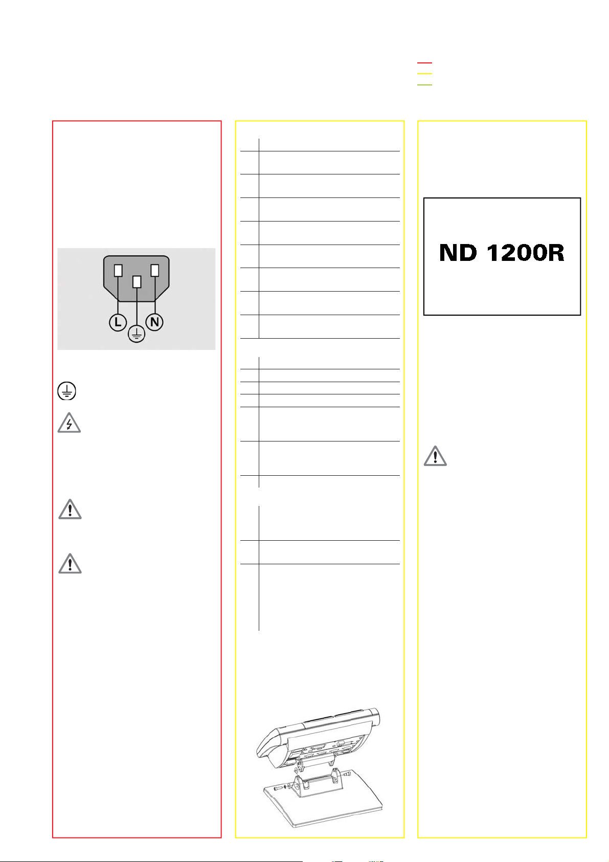
ND 1200 R
Radial
Softwar e Version
2.8.x
2/2011
Page 2
quit
cancel
enter
finish
+/-0
4
1
7
5 6
2 3
8 9
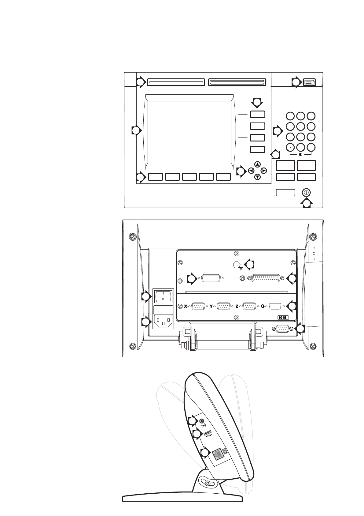
ND 1200 R RADIAL
Front panel
F
C
H
Rear side
A
G
+/-
D
enter
B
E
3
6
1
cancel
finish
quit
I
7
4
Side view
2
5
8
9
10
Page 3
ND 1200 R RADIAL
English
Setup
For detailed description, see www.heidenhain.de
Before Power up
Electrical connection
Line voltage: 100V~ to 240V
(–15 % to +10 %)
Line frequency: 43 Hz to 63 Hz
Line fuse: T1600 mA, 250 V
5 x 20 mm
Power connector wiring
L: Line voltage (brown)
N: Neutral (blue)
Earth ground (yellow/green)
Danger of electr ical shoc k!
Do not open the enclosure•
Never use 3-wire to 2-wire adapters •
or allow the ground connection to
the ND 1200 R to be interrupted or
disconnected.
Caution
Changes to the power cable may be
made only by an electrical technician.
Caution
Do not connect encoders or other
equipment to the ND 1200 R when the
power is on.
Safety Considerations
General accepted safety precautions
must be followed when operating the
ND 1200 R. Failure to observe these
precautions could result in damage to
the equipment, or injury to personnel.
It is understood that safety rules within
individual companies vary. If a confl ict
exists between the material contained
in this guide and the rules of a company
using this system, the more stringent
rules should take precedence.
Controls and Displays
A LCD scr een
B
Soft ke ys: Change to support
functions
C
Axis keys: Enter target
information
D
Command keys: Control
operations
E
Arro w cursor keys: Menu
navigation
F
Fast trac k keys: Programmable
for frequently used functions
G
Numeric k e ypad: Enter numeric
data
H
Send key: Transmit data to PC,
USB printer or USB drive
I
LCD on/off ke y: Turn LCD on or
off and clear data
Connections rear side
1 Pow er switc h
2 Pow er connection with fuse
3
Ground (protective ground)
4
Encoder inputs, X, Y and Z axis.
5
RS-232-C interface f or PC
connection. RS-232 cable must
not include crossovers.
6
Probe connector for
HEIDENHAIN 15 pin universal
touch probe sensor.
7 Unused
Connections side view
8
Audio out, for 3.5 mm
headphone / speaker jack,
monaural, 8 Ohm
9
USB type A int erface for printer
or data storage
10
Remote accessory interf ace
RJ-45 for optional foot switc h or
keypad accessory . Two optional
remote accessories can be used
simultaneously using an RJ-45
splitter.
Mounting
The ND 1200 R is secured to the swivel
slots of the mounting stand or arm
mount by a shoulder screw, a cap
screw mount as shown and associated
washers.
Very important
Please note
For your information
Initial power up
Press the power• switch to power
the ND 1200 R. The startup screen is
displayed. Press the FINISH key to
display the current axis positions on
the DRO screen.
Software setup
The operating parameters of the
ND 1200 R must be confi gured prior
to using it for the fi rst time, and any
time part measurement, reporting or
communication requirements change.
Settings will be retained until:
The data-backup battery is changed•
The data and settings are cleared•
Caution
Setup parameters control the operation
of the ND 1200 R and are passwordprotected. Only qualifi ed personnel
should be given password access to
setup screens.
Access setup menu1.
Press the MENU soft k e y and then the
SETUP sof t k e y. The setup menu is
displayed.
Select the language2.
Use the arrow cursor• keys to highlight
the desired language fi eld.
Press the • YES soft key.
Press the • FINISH key.
Enter password3.
Use the arrow cursor• keys to navigate
to the SUPERVISOR setup screen.
Highlight the • PASSWORD fi eld and
enter the password.
Enable • STARTUP ZERO if a machine
zero will be used for error correction.
Press the • FINISH key.
1
Page 4
ND 1200 R RADIAL
Setup
Operation
Encoder setup4.
Use the arrow cursor• keys to navigate
to the ENCODERS setup screen.
Select an axis and enter the required •
encoder parameters.
Repeat setup for all axes.•
Press the • FINISH key.
Radial Drill setup5.
Use the arrow cursor keys to navigate •
to the RADIAL DRILL setup screen.
Enter the desired parameters and •
press the FINISH key.
Error correction6.
Linear error correction (LEC) methods
can be used to compensate for encoder
and machine measurement errors.
Refer to the ND 1200 R User Guide f or
instructions.
Display formatting7.
Use the arrow cursor keys to navigate •
to the DISPLAY screen.
Enter the desired display resolutions •
and other parameters.
Press the • FINISH key.
Note:
Refer to the ND 1200 R User Guide f or
additional setup functions.
Preparation
Power up the ND 1200 R1.
Check connections to the ND 1200 R.•
Press the • POWER switch to power
the ND 1200 R.
Press the • FINISH key to display the
DRO screen.
Find machine zero2.
Move the stage to cross reference
marks if the system was setup to
establish machine zero at startup.
Select a unit of measure3.
Press the MM (IN) soft k e y to toggle
between mm and inches.
Select coordinates4.
Press the X/Y (R/A) soft k e y to toggle
between rectangular and polar
coordinates
Replacement5.
The ND 1200 R must be parameterized
in accordance with the machine
settings. Transfer the correct parameters
or have a (re)calibration performed.
2
Probing a position
A position can be probed with a hard
probe or a touch probe.
Probing with a hard probe1.
Touch the probe to the edge of the •
workpiece.
Press • ENTER.
Enter the probe diameter.•
Press the arrow cursor key that •
indicates the probe compensation
direction.
Probing with a touch probe2.
Touch the edge of the workpiece with •
the probe.
Aligning the part
Perf orm a sk e w alignment to eliminate
cosine errors resulting from misaligned
parts.
Align the part on the stage1.
Align the reference edge of the part to a
measurement axis.
Perform a skew alignment2.
Press the • DATUM soft key.
Press the • SKEW soft key.
Probe points along the part edge •
aligned to the reference axis.
Press the • FINISH key to complete the
alignment.
Set zero point
The fi rst point of the skew will be used
as the zero point. Use ZERO to c hange
the zero point along the reference axis.
Press the • ZERO soft key.
Press the soft key for the axis to zero •
along (skew edge).
Probe the part edge perpendicular to •
the skew edge.
Note:
The center of a hole can be used as a
point for a skew alignment or setting a
zero point. Ref er to the ND 1200 R User
Guide for detailed instructions.
Move zero point
If the zero point of a part is not reachable
by a probe the zero point can be mov ed.
Press the • DATUM soft key
Press the • MOVE 0 soft key.
Enter the X and Y coordinates to •
move the zero point to.
Press • FINISH.
Target entry
Press the • X or Y axis key.
Enter the desired position to target.•
Press the • ENTER key.
Repeat for the opposite axis.•
Press the • FINISH key. The distance
from the target is displayed.
Hole patterns
Press the • MENU soft key.
Press the • PATTERN soft key.
Press the soft key to select the •
desired pattern.
Enter the desired parameters.•
Press • FINISH.
Programs
Save a program1.
Create a target sequence.•
Press the • MENU soft key.
Press the • PROG soft key.
Press the • SAVE soft key.
Use the numeric keypad to enter a •
name for the program.
Press the • ENTER key.
Run a program2.
Press the • MENU soft key.
Press the • PROG soft key.
Use the arrow cursor keys to highlight •
a program.
Press the • RUN soft key.
Delete a program3.
Press the • MENU soft key.
Press the • PROG soft key.
Use the arrow cursor keys to highlight •
a program.
Press the • DELETE soft key.
Press the • YES soft key.
Note:
Refer to the ND 1200 R User Guide f or
detailed instructions.
DR. JOHANNES HEIDENHAIN GmbH
Dr.-Johannes-Heidenhain-Straße 5
83301 Traunreut, Germany
{ +49 8669 31-0
| +49 8669 5061
E-mail: info@heidenhain.de
www.heidenhain.de
Page 5

ND 1200 R RADIAL
Deutsch
Einric hten
Eine genaue Beschreibung fi nden Sie unter www.heidenhain.de
Vor der Inbetriebnahme
Elektrischer Anschluss
Netzspannung: 1 00 V~ bis 240 V
(–15 % bis +10 %)
Netzfrequenz: 43 Hz bis 63 Hz
Netzsicherung: T1600 mA, 250 V
5 x 20 mm
Anschluss des Netzsteckers
L: Phase (braun)
N: Nullleiter (blau)
Schutzleiter (gelb/grün)
Stromschlaggefahr!
Gerät nicht öffnen!•
Schutzleiter der ND 1200 R darf nie •
unterbrochen sein, auch nicht bei
Anschluss über Adapter.
Achtung
Änderungen am Netzkabel nur durc h
Elektrotechniker!
Achtung
Keine Messgeräte oder anderen Geräte
anschließen, während die ND 1200 R
eingeschaltet ist.
Sicherheitsvorkehrungen
Für den B etrieb der ND 1200 R
gelten die allgemein anerkannten
Sicherheitsvorschriften. Nichtbeachtung
dieser Sicherheitsvorschriften kann zu
Sach- oder Personenschäden führen.
Die Sicherheitsvorschriften können je
nach Unternehmen variieren. Im F alle
eines Konfl ikts zwischen dem Inhalt
dieser Kurzanleitung und den internen
Regelungen eines Unternehmens, in
dem dieses Gerät verwendet wird,
sollten die strengeren Regelungen
gelten.
Anzeige- und Bedienelemente
A LCD-Bildschirm
B
Softke ys: funktionsabhängig
C
Achstasten: Eingabe v on
Zielinformationen
D
Befehlstasten: B estätigung v on
Aktionen
E
Pfeiltasten: Na vigation durch die
Menüs
F
Schnellzugrif fstast en: pro-
grammierbar für häufi g genutzte
Funktionen
G
Zahlenblock: Eingabe von Zahlen
H
Taste SENDEN: Daten an
PC, USB-Druc k er oder USBSpeichermedium senden
I
Taste LCD Ein/Aus: LCD-Anzeige
ein-/ausschalten oder Daten
löschen
Anschlüsse auf der Rückseite
1 Netzschalter
2 Netzanschluss mit Sicherung
3 Erdungsanschluss
(Schutzerdung)
4
Messgerät-Eingänge, X-, Y- und
Z-Achse
5
Schnittstelle V .24/RS-232-C
für PC-Anschluss. Kabel für V.24/
RS-232 darf keine gekreuzten
Adern haben.
6
Anschluss für 15-poliges univ ersel-
les Tastsy stem von HEIDENHAIN
7 Nicht belegt
Anschlüsse auf der Seite
8
Audio-Ausgang für Kopfhörer
3,5 mm / Lautsprecherbuchse,
Einohr , 8 Ohm
9
USB-Schnittstelle, Typ A, für
Druc k er oder Speichermedien
10 Schnittstelle RJ-45 für Fernbe-
dienung über optionalen Fuß-
schalter oder externes B edienfeld.
Mithilfe eines RJ-45-Split ters können zwei Fernbedienungsoptionen gleichzeitig genutzt w erden.
Montage
Die ND 1200 R wird mit einer
Passsc hraube, einer K opfschraube und
passenden Unterlegscheiben in den
Schwenkschlitzen des Montagefußes
oder -arms befestigt (s. Abb.)
unbedingt beachten
wichtig
informativ
Erstinbetriebnahme
Zum Einschalten der ND 1200 R •
den Netzschalter drücken. Der
Startbildschirm erscheint. Zur Anzeige
der aktuellen Achspositionen (ISTPOSITION) Taste FINISH drücken.
Software-Setup
Die Betriebsparameter der ND 1200 R
müssen vor der Erstinbetriebnahme und
immer , w enn sich die Anforderungen an
die Vermessung von T eilen, B erichterstellung oder Kommunikation ändern,
konfi guriert werden.
Einstellungen werden beibehalten bis:
Batterie für Daten-Backup gewechselt •
wird.
Daten und Einstellungen gelöscht •
werden.
Achtung
Die Setup-Parameter steuern die
Bedienung der ND 1200 R und sind
passwortgeschützt. Das Passwort für
die Setup-Menüs sollte nur an gesc hulte
Personen w eitergegeben w erden.
Menü „Setup“ öffnen1.
MENÜ-Softke y und dann Softkey SETUP
drücken. Das Menü „Setup“ wird
angezeigt.
Sprache wählen2.
Mit den Pfeiltasten• das gewünschte
Sprachfeld markieren.
Softkey • JA drücken.
Taste • FINISH drücken.
Passwort eingeben3.
Mit den Pfeiltasten• zum Untermenü
PASSWORT navigieren.
Das • PASSWORT-Datenfeld markieren
und Passwort eingeben.
NULLEN AM START• aktivieren, wenn
ein Maschinen-Bezugspunkt für die
Fehlerkompensation verwendet
werden soll.
Taste • FINISH drücken.
1
Page 6

ND 1200 R RADIAL
Einric hten
Bedienung
Setup für Messgerät4.
Mit den Pfeiltasten• zum Untermenü
MESSGERÄT navigieren.
Achse auswählen und erforderliche •
Messgerät-Parameter eingeben.
Setup für alle Achsen wiederholen.•
Taste • FINISH drücken.
Setup für Radial Drill5.
Mit den Pfeiltasten zum Untermenü •
RADIAL DRILL navigieren.
Gewünschte Parameter eingeben und •
mit Taste FINISH bestätigen.
Fehlerkompensation6.
Messgerät- und Maschinenmessf ehler
können mit der linearen
Fehlerkompensation (LEC) k orrigiert
werden. Siehe auch Geräte-Handbuch
ND 1200 R.
Anzeigeformat7.
Mit den Pfeiltasten zum Untermenü •
ANZEIGE navigieren.
Anzeigeaufl ösungen und weitere •
Parameter eingeben.
Taste • FINISH drücken.
Hinweis:
Für w eitere Einrichtefunktionen, siehe
auch Geräte-Handbuch ND 1200 R.
Vorbereitung
ND 1200 R einschalten1.
Anschlüsse der ND 1200 R •
überprüfen.
Zum Einschalten der ND 1200 R den •
NETZSCHALTER drücken.
Taste • FINISH drücken, um die
Anzeige „IST-Position“ zu öffnen.
Maschinen-Nullpunkt ermitteln2.
Zum Überfahren der Ref erenzmark en
Tisch verschieben, wenn beim
Systemstart ein Masc hinenBezugspunkt festgelegt w erden soll.
Maßeinheit wählen3.
Softke y MM (IN) drücken, um zwischen
Millimeter und Zoll umzuschalten.
Koordinatensystem auswählen4.
Softke y X/Y (R/A) drücken, um
zwischen kartesischem und polarem
Koordinatensystem umzusc halten.
Gerät austauschen5.
Die Parametrierung der ND 1200 R muss
auf die Maschine abgestimmt sein.
Übertragen Sie die korrekten Parameter
oder lassen Sie eine Kalibrierung
durchführen.
2
Position erfassen
Eine Position kann mittels Taststift oder
Kantentaster erfasst werden.
Erfassung mittels Taststift1.
Werkstückkante mit dem Taststift •
antasten.
ENTER• drücken.
Taststift-Durchmesser eingeben.•
Pfeiltaste für die Richtung der •
Taststiftkorrektur drücken.
Erfassung mittels Kantentaster2.
Werkstückkante mit dem •
Kantentaster antasten.
Teileausrichtung
Mit der T eileausrichtung werden
Kosinus-Messfehler aufgr und f alsch
ausgerichteter T eile beseitigt.
Werkstück auf dem Tisch 1.
ausrichten
Bezugskante des Werkstücks an einer
Messachse ausrichten.
Ausrichtung durchführen2.
Softkey • BEZUGSPUNKT drücken.
Softkey • AUSRICHTUNG drücken.
Punkte entlang der an der Messachse •
ausgerichteten Werkstückkante
erfassen.
Taste • FINISH drücken, um die
Ausrichtung abzuschließen.
Nullpunkt setzen
Der erste Punkt der Ausrichtung dient
als Nullpunkt. Mit NULLEN kann der
Nullpunkt entlang der Bezugsachse
verschoben w erden.
Softkey • NULLEN drücken.
Softkey für die Achse, an der der •
Nullpunkt verschoben werden soll,
drücken (Ausrichtungskante).
Werkstückkante senkrecht zur •
Ausrichtkante antasten.
Hinweis:
Ein Loch-Mittelpunkt kann als
Ausric ht ungspunkt dienen oder zum
Nullpunkt-Setzen verwendet werden.
Eine genaue Anleitung fi nden Sie im
Geräte-Handbuch ND 1200 R.
Nullpunkt verschieben
Wenn der Nullpunkt eines Teils mit dem
Tastsystem nicht zu erreic hen ist, kann
er verschoben w erden.
Softkey • BEZUGSPUNKT drücken.
Softkey • NULL VER. drücken.
Die X- und Y-Koordinaten für die •
Nullpunktverschiebung eingeben.
FINISH• drücken.
Zieleingabe
Taste für die • X- oder Y-Achse drücken.
Gewünschte Zielposition eingeben.•
Mit • ENTER bestätigen.
Für die gegenüberliegende Achse •
wiederholen.
Taste • FINISH drücken. Die Entfernung
zum Ziel wird angezeigt.
Lochmuster
Softkey • MENÜ drücken.
Softkey • LÖCHER drücken.
Mittels Softkey das gewünschte •
Lochmuster auswählen.
Die gewünschten Parameter •
eingeben.
FINISH• drücken.
Programme
Programm speichern1.
Zielsequenz erstellen.•
Softkey • MENÜ drücken.
Softkey • PROG drücken.
Softkey • SPEICHERN drücken.
Mittels Zahlenblock einen •
Programmnamen eingeben.
Mit • ENTER bestätigen.
Programm ausführen2.
Softkey • MENÜ drücken.
Softkey • PROG drücken.
Mit den Pfeiltasten ein Programm •
markieren.
Softkey • AUSF. drücken.
Programm löschen3.
Softkey • MENÜ drücken.
Softkey • PROG drücken.
Mit den Pfeiltasten ein Programm •
markieren.
Softkey • LÖSCH. drücken.
Softkey • JA drücken.
Hinweis:
Eine genaue Anleitung fi nden Sie im
Geräte-Handbuch ND 1200 R.
DR. JOHANNES HEIDENHAIN GmbH
Dr.-Johannes-Heidenhain-Straße 5
83301 Traunreut, Germany
{ +49 8669 31-0
| +49 8669 5061
E-mail: info@heidenhain.de
www.heidenhain.de
Page 7

ND 1200 R RADIAL
Tilting base
Mounting base
158.75
A
203.2
260
B
M6.3 - 1.3 x 16.5
(1/4 - 20" x 0.65")
M5
200
203.5
mm
Tolerancing ISO 8015
ISO 2768 - m H
< 6 mm: ±0.2 mm
125
27.5
38
43.5
55
B
Page 8

4
XYZQ » 1 V
PP
4 12 2 10 1 9 3 11 14 7 5/6/8/
13/15
» 1 V
pp
U
Sensor
P
U
P
0 V Sensor
0 V
A+ A– B+ B– R+ R– /
4
XYZQ « TTL
762345981
« TTL U
P
0 V U
a1
U
a2
£
U
a0
¤
/
5
V.24/RS-232-C
123456789
/ TXD RXD DTR Signal
DSR RTS CTS /
GND
6
HEIDENHAIN
Universal T ouch Probe
1 2 4 5 6 8 10 11 13 15 3/7/9/
12/14
GND LED+ 12 Vdc 15 Vdc 5 Vdc GND In S+ I(2) S+ I(1) LED- /
7
Parallel Input/Output Port
23456789114161718
Data
Out 1
Data
Out 2
Data
Out 3
Data
Out 4
Data
Out 5
Data
Out 6
Data
Out 7
Data
Out 8
Data
Out 9
Data
Out 10
Data
Out 11
Data
Out 12
Signal
GND
15 13 12 11 1 0 19 20 21 22 23 24 25 –
Data
In 1
Data
In 2
Data
In 3
Data
In 4
Data
In 5
Signal
GND
Signal
GND
Signal
GND
Signal
GND
Signal
GND
Signal
GND
Signal
GND
/
Page 9

8
Audio out
9
USB T ype A
Data I/O
12 3 4
/ Data (-) Data (+) Data
10
RJ-45
Remote Footswitch
12
Out Signal GND
GND
12345678
Signal
GND
S-2
NO
S-1
NO
/ S-1 and S-2
CO
///
Page 10

DR. JOHANNES HEIDENHAIN GmbH
Dr.-Johannes-Heidenhain-Straße 5
83301 Traunreut, Germany
{ +49 8669 31-0
| +49 8669 5061
E-mail: info@heidenhain.de
Technical support | +49 8669 32 -1000
Measuring systems { +49 8669 31-3104
E-mail: service.ms-support@heidenhain.de
TNC support { +49 8669 31-3101
E-mail: service.nc-support@heidenhain.de
NC programming { +49 8669 31-3103
E-mail: service.nc-pgm@heidenhain.de
PLC programming { +49 8669 31-3102
E-mail: service.plc@heidenhain.de
Lathe controls { +49 8669 31-3105
E-mail: service.lathe-support@heidenhain.de
www.heidenhain.de
Page 11

DR. JOHANNES HEIDENHAIN GmbH
Dr.-Johannes-Heidenhain-Straße 5
83301 Traunreut, Germany
{ +49 8669 31-0
| +49 8669 5061
E-mail: info@heidenhain.de
www.heidenhain.de
Vollständige und weitere Adressen siehe www.heidenhain.de
For complete and further addr esses see www.heidenhain.de
DE HEIDENHAIN T ec hnisches Bür o Nor d
12681 Berlin, Deutschland
{ 030 54705-240
HEIDENHAIN T ec hnisches Bür o Mit t e
08468 Heinsdorfergrund, Deutschland
{ 03765 69544
HEIDENHAIN Technisches Büro West
44379 Dortmund, Deutschland
{ 0231 618083-0
HEIDENHAIN T ec hnisches Bür o Südw est
70771 Leinfelden-Ec hterdingen, Deutschland
{ 0711 993395-0
HEIDENHAIN T ec hnisches Bür o Südost
83301 T raunreut, Deutschland
{ 08669 31-1345
AR NAKASE SRL.
B1653AO X Villa Ballester, Argentina
www.heidenhain.com.ar
AT HEIDENHAIN Techn. Büro Öster r eic h
83301 T raunreut, Germany
www.heidenhain.de
AU FCR Motion Technology Pty. Ltd
Laverton North 3026, A ustralia
E-mail: vicsales@fcrmotion.com
BA Bosnia and Herzegovina − SL
BE HEIDENHAIN NV/SA
1760 Roosdaal, Belgium
www.heidenhain.be
BG ESD Bulgaria Ltd.
Sofi a 1172, Bulgaria
www.esd.bg
BR DIADUR Indústria e Comércio Ltda.
04763-070 – São Paulo – SP, Brazil
www.heidenhain.com.br
BY Belarus
GERTNER Service GmbH
50354 Huerth, Germany
www.gertner.biz
CA HEIDENHAIN CORPORATION
Mississauga, OntarioL5T2N2, Canada
www.heidenhain.com
CH HEIDENHAIN (SCHWEIZ) AG
8603 Schwerzenbach, Switzerland
www.heidenhain.ch
CN DR. JOHANNES HEIDENHAIN
(CHINA) Co., Ltd.
Beijing 1 01312, China
www.heidenhain.com.cn
CZ HEIDENHAIN s.r.o.
102 00 Praha 10, Czech Republic
www.heidenhain.cz
DK TP TEKNIK A/S
2670 Greve, Denmark
www.tp-gr uppen.dk
ES F ARRESA ELECTRONICA S .A.
08028 Barcelona, Spain
www.f ar resa.es
FI HEIDENHAIN Scandinavia AB
02770 Espoo, Finland
www.heidenhain.fi
FR HEIDENHAIN FRANCE sarl
92310 Sèvres, France
www.heidenhain.fr
GB HEIDENHAIN (G.B.) Limit ed
Burgess Hill RH15 9RD , United Kingdom
www.heidenhain.co.uk
GR MB Milionis Vassilis
17341 Athens, Greece
www.heidenhain.gr
HK HEIDENHAIN LTD
Kowloon, Hong Kong
E-mail: sales@heidenhain.com.hk
HR Croatia − SL
HU HEIDENHAIN Kereskedelmi Képviselet
1239 Budapest, Hungary
www.heidenhain.hu
ID PT Servitama Era Toolsindo
Jakarta 13930, Indonesia
E-mail: ptset@group.gts.co.id
IL NEUMO VARGUS MARKETING LTD.
Tel Aviv 61570, Israel
E-mail: neumo@neumo-vargus.co.il
IN HEIDENHAIN Optics & Electronics
India Privat e Limit ed
Chetpet, Chennai 600 031, India
www.heidenhain.in
IT HEIDENHAIN ITALIANA S.r.l.
20128 Milano, Italy
www.heidenhain.it
JP HEIDENHAIN K.K.
Tokyo 102-0083, Japan
www.heidenhain.co.jp
KR HEIDENHAIN Korea L TD .
Gasan-Dong, Seoul, Korea 153-782
www.heidenhain.co.kr
ME Montenegro − SL
MK Macedonia − BG
MX HEIDENHAIN CORPORA TION MEXICO
20235 Aguascalientes, Ags., Mexico
E-mail: info@heidenhain.com
MY ISOSERVE Sdn. Bhd
56100 Kuala Lumpur, Malaysia
E-mail: isoserve@po.jaring.my
NL HEIDENHAIN NEDERLAND B.V.
6716 BM Ede, Netherlands
www.heidenhain.nl
NO HEIDENHAIN Scandinavia AB
7300 Orkanger, Norway
www.heidenhain.no
PH Machinebanks` Corporation
Quezon City, Philippines 1113
E-mail: info@machinebanks.com
PL APS
02-489 Warszawa, Poland
www.apserwis.com.pl
PT FARRESA ELECTRÓNICA, LD A.
4470 - 177 Maia, Portugal
www.f ar resa.pt
RO HEIDENHAIN Reprezentant¸a˘ Romania
Bras¸ov, 500338, Romania
www.heidenhain.ro
RS Serbia − BG
RU OOO HEIDENHAIN
12531 5 Mosco w, Russia
www.heidenhain.r u
SE HEIDENHAIN Scandinavia AB
12739 Skärholmen, Sw eden
www.heidenhain.se
SG HEIDENHAIN PACIFIC PTE LTD.
Singapore 408593
www.heidenhain.com.sg
SK KOPRETINA TN s.r.o.
91 10 1 T rencin, Slovakia
www.k opretina.sk
SL Posredništvo HEIDENHAIN
NA VO d.o.o.
2000 Maribor, Slovenia
www.heidenhain-hubl.si
TH HEIDENHAIN (THAILAND) LTD
Bangkok 10250, T hailand
www.heidenhain.co.th
TR T&M Mühendislik San. ve Tic. LTD. S¸TI·.
34728 Ümraniye-Istanbul, Turk e y
www.heidenhain.com.tr
TW HEIDENHAIN Co., Ltd.
T aichung 40768, Taiw an R.O .C.
www.heidenhain.com.tw
UA Gertner Service GmbH Büro Kiev
01133 Kie v, Ukraine
www.gertner.biz
US HEIDENHAIN CORPORATION
Schaumburg, IL 60173-5337, USA
www.heidenhain.com
VE Maquinaria Diekmann S.A.
Caracas, 1040-A, Venezuela
E-mail: purchase@diekmann.com.ve
VN AMS Co. Ltd
HCM City, Vietnam
E-mail: davidgoh@amsvn.com
ZA MAFEMA SALES SERVICES C.C.
Midrand 1685, South Africa
www.heidenhain.co.za
Zum Abhef t en hier falzen! / Fold here for fi ling!
732 602-90 · Ver00 · 0.5 · 2/2011 · Printed in USA
 Loading...