

Page 1
Operating Instructions
ND 1200R
Radial
Software Version
2.8.x
English (en)
6/2013
Page 2

Page 3
ND 1200R Introduction
quit
cancel
enter
finish
+/-0
4
1
7
5 6
2 3
8 9
12345
678
9
quit
cancel
enter
finish
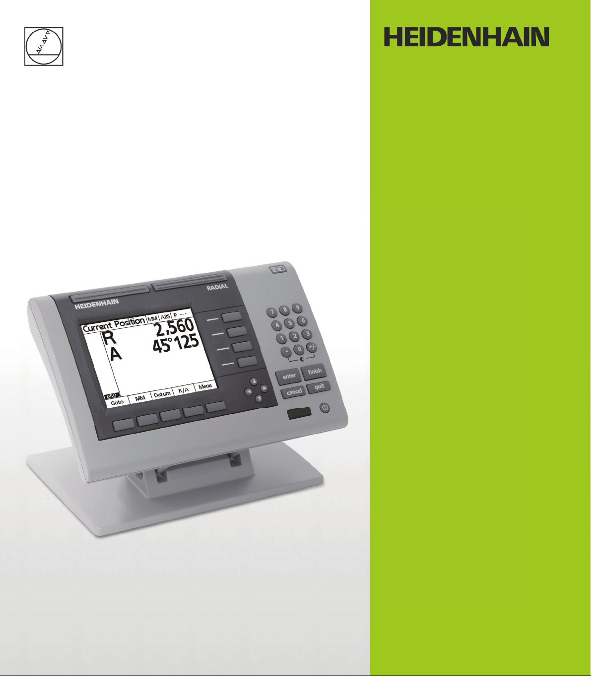
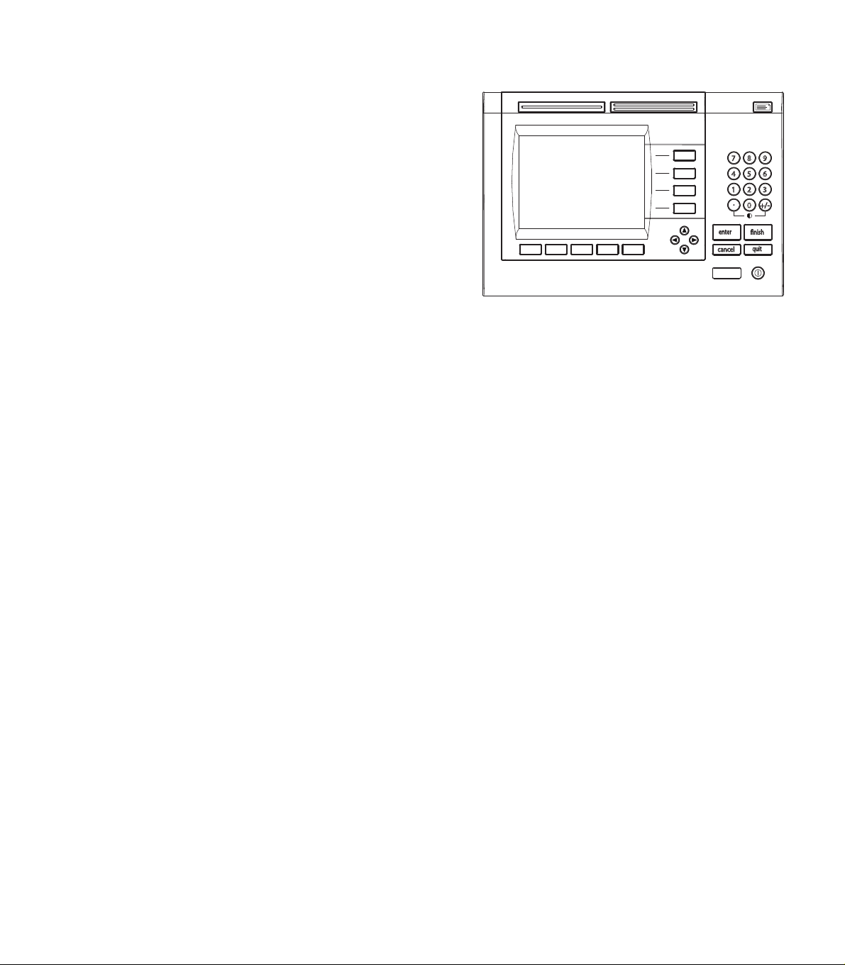
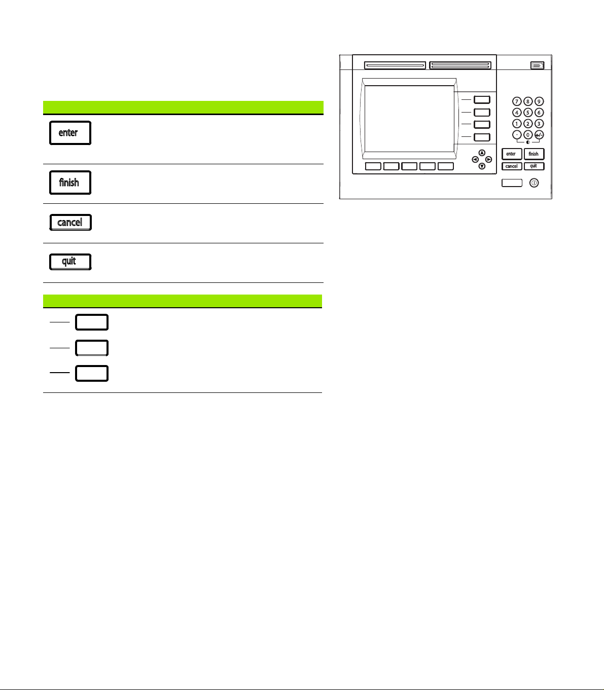
1 LCD screen
2 Soft keys
3 Axis keys
4 Command keys
5 Arrow keys
6 Wide keys
7 Numeric keypad
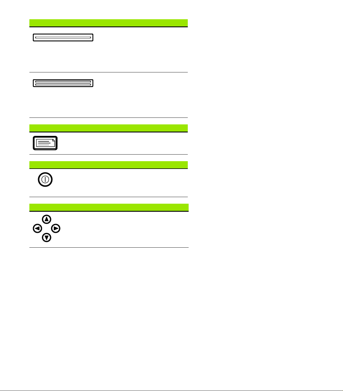
8 Send key
9 LCD On/Off key
ND 1200R panel keys
Panel keys are used to enter target position coordinates, send data via
RS-232 and USB ports and configure operational parameters.
Panel function key Panel key
Soft keys: Functions change in support of the activities displayed
on the LCD.
Axis keys: used to enter target positions.
Command keys: Control target and data entry processes.
Arrow keys: Used to scroll through lists and navigate menus and
setup screen data fields.
ND 1200R Radial 3
Page 4
Panel function key Panel key
+/-0
4
1
7
5 6
2 3
8 9
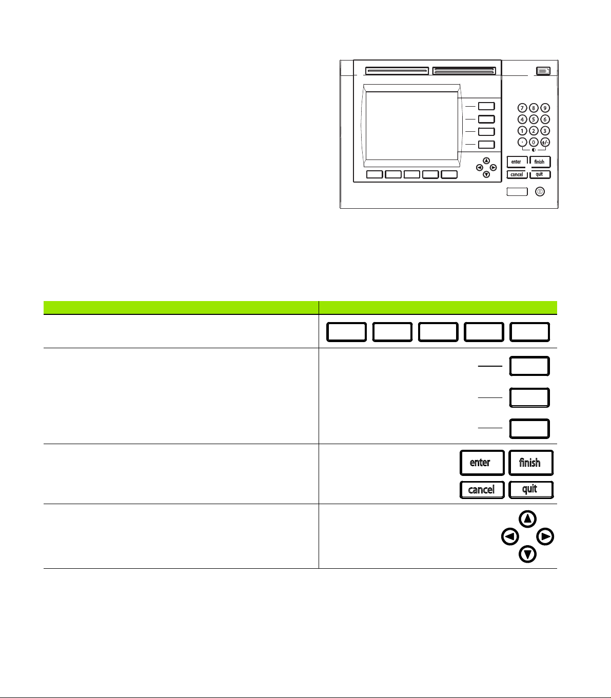
Wide keys: Two programmable Wide keys are used to perform
frequently used functions. These keys can easily be located by
touch without taking your eyes off the part. By default the left
fast track key is assigned the SEND2 function and the right is
assigned the ZERO2 function. Users can program either wide
key as described later in the Hotkeys portion of Chapter 2:
Installation, Setup and Specifications.
Numeric keypad: Used to enter numeric data. Additionally, the
decimal point key and +/- key are used to adjust the contrast
of the LCD display.
Send key: Used to transmit target data to a computer or USB
printer.
LCD On/Off key: Press the LCD on/off button to turn the LCD
display off without removing power from the ND 1200R. Press
the button a second time to restore the LCD display. Additionally,
the LCD On/Off key can be used to clear target data, datums and
skews.
4 Preface
Page 5
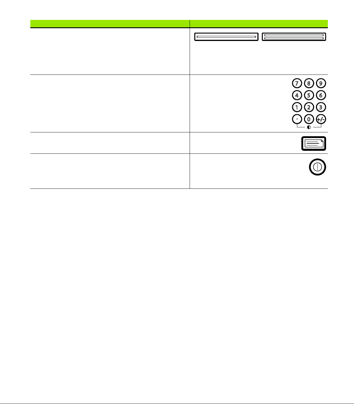
ND 1200R rear panel
1
2
3
5
4
678
123
1 Power switch
2 Power cord connector and fuse holder
3 Power ground access
4 HEIDENHAIN 15 pin universal touch probe sensor
5 Measurement axis connectors
6 RS-232 serial port connector
7 Not supported in the ND 1200R
8 Tilt base mechanical tightness adjustment
ND 1200R side panel
1 Speaker/headset jack
2 USB Type A connector
3 RJ-45 Foot switch/hand switch/keypad connector
ND 1200R Radial 5
Page 6
Information contained in this manual
This User's manual covers the operation, installation, setup and
specifications of the ND 1200R. Operating information is contained in
chapter 1. Installation, setup instructions and specifications are
contained in chapter 2.
Fonts used in this manual
The following fonts are used to indicate operator controls or to show
emphasis:
Operator controls - SOFT KEYS and other PANEL KEYS are shown
in upper case.
Emphasis - Items of special interest or concepts that are
emphasized to the user are shown in bold type.
Showing sequences of key presses
The ND 1200R user performs sequences of soft key and panel key
presses to complete tasks. These sequences are indicated using text
as shown in the following example:
Press the MENU soft key, press the DATUM soft key and then
press the ZERO soft key is sometimes abbreviated as:
Press MENU>DATUM>ZERO
Symbols within notes
Notes are marked with symbols on the left indicating the type, or
potential severity of the information.
General Information
This is additional or supplementary information about an
activity or concept.
Warning
This warns of a situation or condition that could lead to
measurement errors, equipment malfunction or
equipment damage. Do not proceed until the message is
read and understood.
Caution - Risk of electric shock
This warns of a situation or condition that could lead to
electrical shock and to personal injury or death. Do not
proceed until the message is read and understood.
6 Preface
Page 7
Safety considerations
General accepted safety precautions must be followed when
operating the system. Failure to observe these precautions could
result in damage to the equipment, or injury to personnel. It is
understood that safety rules within individual companies vary. If a
conflict exists between the material contained in this manual and the
rules of a company using this system, the more stringent rules should
take precedence.
The ND 1200R is equipped with a 3-wire power plug that
includes a separate ground connection. Always connect
the power plug to a 3-wire grounded outlet. Use of 2-wire
power plug adapters or any other connection accessories
that remove the third grounded connection create a safety
hazard and should not be permitted.
Unplug the ND 1200R from the power outlet and seek the
assistance of a qualified service technician if:
The power cord is frayed or damaged or the power plug
is damaged
Liquid is spilled or splashed onto the enclosure
The ND 1200R has been dropped or the exterior has
been damaged
The ND 1200R exhibits degraded performance or
indicates a need for service some other way
ND 1200R measurement axes
The ND 1200R DRO can display 2 or 3 axes depending on the model
purchased. DRO screen images used throughout this manual show
different numbers of axes and are for illustration only.
Software version
The software version is shown in the About setup screen discussed
later in chapter 2.
Cleaning
Use only a cloth dampened with water and a mild detergent for
cleaning the exterior surfaces. Never use abrasive cleaners, and never
use strong detergents or solvents. Only dampen the cloth, do not use
a cleaning cloth that is dripping wet.
ND 1200R Radial 7
Page 8

8 Preface
Page 9

1 Operation
1.1 ND 1200R Overview ......................................................................................................................................... 12
1.2 Basic Functions of the ND 1200R..................................................................................................................... 13
Switching on the ND 1200R ........................................................................................................................ 13
Establishing a repeatable machine zero....................................................................................................... 14
Switching off the ND 1200R........................................................................................................................ 14
Panel key descriptions................................................................................................................................. 15
LCD screen and soft key layout................................................................................................................... 17
DRO mode screen and soft keys ......................................................................................................17
Distance from target mode screen and soft keys.............................................................................18
ND 1200R Menus ........................................................................................................................................ 19
1.3 Preparing to drill ................................................................................................................................................ 23
Power-up the ND 1200R.............................................................................................................................. 23
Establish machine zero................................................................................................................................ 23
Adjust LCD screen contrast......................................................................................................................... 24
Select unit of linear measure....................................................................................................................... 24
Select a coordinate system ......................................................................................................................... 24
Probing a position ........................................................................................................................................ 25
Select a probe diameter............................................................................................................................... 26
Aligning the part to an axis .......................................................................................................................... 27
Establish a datum ........................................................................................................................................ 29
Setting a datum from a probed point ................................................................................................29
Setting a datum from a skew line .....................................................................................................29
Setting a datum on the center of a hole............................................................................................29
Moving a datum........................................................................................................................................... 30
1.4 Targets .............................................................................................................................................................. 31
Entering a target .......................................................................................................................................... 31
Entering an absolute target position..................................................................................................31
Entering an incremental target position ............................................................................................33
Editing and clearing targets ......................................................................................................................... 35
Editing a target ..................................................................................................................................35
Deleting a target................................................................................................................................35
Clearing the target list .......................................................................................................................35
Marking a target........................................................................................................................................... 36
1.5 Target patterns.................................................................................................................................................. 37
Frame pattern .............................................................................................................................................. 38
Rectangle pattern ........................................................................................................................................ 39
Line pattern.................................................................................................................................................. 40
Circle pattern ............................................................................................................................................... 41
1.6 Target programs................................................................................................................................................ 42
Saving a program......................................................................................................................................... 42
Running a program ...................................................................................................................................... 43
Mirroring a program..................................................................................................................................... 44
Deleting a program .............................................................................................................
1.7 Navigating to a target........................................................................................................................................ 46
......................... 45
ND 1200R Radial 9
Page 10

2 Installation, Setup and Specifications
2.1 ND 1200R Shipment Contents ..........................................................................................................................48
Items included with the ND 1200R ..............................................................................................................48
Optional items possibly included..................................................................................................................48
Repackaging the ND 1200R .........................................................................................................................49
2.2 Hardware Installation.........................................................................................................................................50
Assembling the mounting stand ..................................................................................................................50
Benchtop location and mounting ......................................................................................................50
Arm mounting (optional) ...................................................................................................................51
Connecting power........................................................................................................................................52
Connecting encoders and probes.................................................................................................................53
Connecting a computer................................................................................................................................54
Connecting a headphone..............................................................................................................................55
Connecting a USB printer.............................................................................................................................55
Connecting an optional foot switch or remote keypad.................................................................................56
2.3 Software setup ..................................................................................................................................................57
Setup menu..................................................................................................................................................58
Setup example: entering the supervisor password......................................................................................59
Order of setup..............................................................................................................................................61
Language selection and product version......................................................................................................62
Supervisor password....................................................................................................................................63
Encoder configuration ..................................................................................................................................65
Encoders screen ...............................................................................................................................65
Misc screen ......................................................................................................................................68
Probe configuration ......................................................................................................................................69
Radial screen.....................................................................................................................................69
Error correction.............................................................................................................................................71
Linear error correction (LEC).............................................................................................................71
Display formatting ........................................................................................................................................74
Display screen...................................................................................................................................74
Hot key assignments....................................................................................................................................76
Hot keys screen................................................................................................................................76
Print formatting ............................................................................................................................................79
Print screen.......................................................................................................................................79
Port configuration.........................................................................................................................................81
Ports screen......................................................................................................................................81
Audio volume ...............................................................................................................................................85
Misc screen ......................................................................................................................................85
Key repeat rate adjustment..........................................................................................................................86
Misc screen ......................................................................................................................................86
Screen saver activation ................................................................................................................................87
Misc screen ......................................................................................................................................87
Time and date settings.................................................................................................................................88
Clock screen .....................................................................................................................................88
2.4 Specifications.....................................................................................................................................................89
Dimensions ..................................................................................................................................................90
Arm mount bracket ...........................................................................................................................91
10
Page 11

Operation
Page 12
1.1 ND 1200R Overview
quit
cancel
enter
finish
+/-0
4
1
7
5 6
2 3
8 9
The ND 1200R is an advanced digital readout (DRO) system for radial
drilling machines using analog or TTL encoders. The system allows the
operator to directly enter either cartesian or polar coordinates for
target positions. This alleviates the requirement of either pre-drilling
holes or a previous operation of marking out the holes on an expensive
machine elsewhere. The system defaults to cartesian coordinates
when entering target positions and polar coordinates when navigating
to a target.
The following functions are available in the ND 1200R:
Reference mark evaluations for distance-coded and single reference
encoders
Linear error correction
1.1 ND 1200R Overview
Multilingual LCD user interface: language is selected by the user
Soft key functions under LCD change to support different user
activities
Arrow keys for easy navigation of lists and menus
Skew compensation for part alignment, eliminating the need for
time-consuming fixturing
Absolute and incremental targeting
Axis zero for establishing a datum
Number keypad with:
Number keys for data entry
Decimal point and +/- keys for data entry and LCD screen contrast
adjustment
User-defined hot keys that program panel and optional remote keys
to initiate commonly used functions.
User-defined programs to save target sequences
Direct entry of cartesian or polar target coordinates
User-defined drilling patterns for:
Frame pattern
Rectangular pattern
Line pattern
Circle pattern
Speaker jack outputs for quiet or noisy environments
Optional remote foot switch and keypad facilitate measurement
when the user is not close to the front panel
ND 1200R Front panel
12 1 Operation
Page 13
1.2 Basic Functions of
finish
the ND 1200R
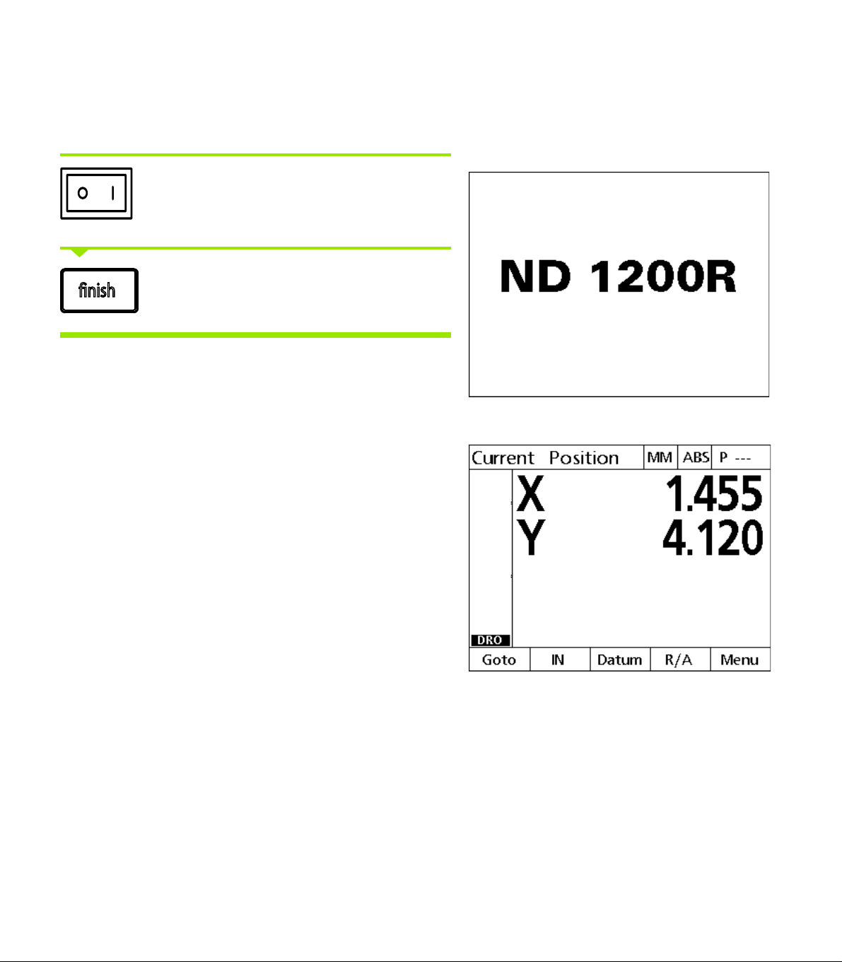
Switching on the ND 1200R
Switch on the ND 1200R. The POWER switch is
located on the rear of the enclosure. After switching
the power on, or after a power failure, the power-up
screen will be displayed.
Press the FINISH key to advance from the power-up
screen to the DRO.
Your ND 1200R is now ready for operation and is in the Current
Position operating mode. Encoder position values will be displayed for
all axes.
Power-up screen
DRO screen
1.2 Basic Functions of the ND 1200R
ND 1200R Radial 13
Page 14
Establishing a repeatable machine zero
If your ND 1200R was configured to establish a machine zero upon
power-up, a message will be displayed asking you to cross reference
marks or enter hard-stop axis reference positions. The machine zero is
used by the ND 1200R to apply error correction data. To establish a
repeatable machine zero you must either:
Move the stage to have encoder reference mark crossings
recognized on each axis or
move the stage to the hard-stop reference position and press
ENTER on each axis when no encoder reference marks are present.
If the requirement to cross reference marks is bypassed
by pressing the CANCEL soft key, error correction data
that might be stored in your ND 1200R will not be
applied.
Switching off the ND 1200R
Switch the ND 1200R off. The parameter settings,
error compensation tables and recorded programs
that have been saved during operation will be
1.2 Basic Functions of the ND 1200R
retained in memory.
14 1 Operation
Page 15
Panel key descriptions
quit
cancel
enter
finish
+/-0
4
1
7
5 6
2 3
8 9
enter
finish
cancel
quit
Descriptions of panel key functions are provided in the following
pages for COMMAND, AXIS, WIDE, SEND, LCD ON/OFF and
ARROW keys. Soft key functions are also described later in the next
section as part of screen and soft key layout descriptions.
Command keys Function
Enter data: Press the enter key to enter
values into configuration fields. Pressing the
enter key indicates that data in a field is ready
for use.
Finish a target entry: Press the finish key to
complete a target entry or select the next
target in a program.
Delete data or target: Press the cancel key
to delete data in configuration fields or any
highlighted target from the target list.
Quit current activity: Press the quit key to
abandon the current task and return to the
DRO screen or to exit the target list.
ND 1200R Panel keys
AXIS keys Function
Enter a target: Press an Axis key to enter
target position coordinates.
ND 1200R Radial 15
1.2 Basic Functions of the ND 1200R
Page 16
WIDE keys Function
SEND key Function
Transmit target data: Press the SEND key
to transmit target data to a computer or a
USB printer.
LCD ON/OFF key Function
1.2 Basic Functions of the ND 1200R
Turn the LCD off or clear data: Press the
LCD ON/OFF key to toggle between LCD on
and LCD off, or to clear target data, datums
and part alignments (skews).
Left frequently used function:
Press the left WIDE key to initiate
the function programmed for this
key. The factory default function for
this key is SEND2. Refer to "Hot key
assignments” on page 76 for
additional information.
Right frequently used function:
Press the right WIDE key to initiate
the function programmed for this
key. The factory default function for
this key is ZERO2. Refer to "Hot key
assignments” on page 76 for
additional information.
ARROW keys Function
Navigate menus and setup screen
data fields.
16 1 Operation
Page 17
LCD screen and soft key layout
ND 1200R LCD screens display information in one of three operating
modes:
DRO mode displays current positions of axes
Distance from target mode displays the distance from a target
position
Setup mode displays ND 1200R setup screens
Soft keys change to support activities shown on the screens.
Setup screens and soft keys are described in Chapter 2:
Installation, Setup and Specifications.
DRO mode screen and soft keys
The DRO screen shows:
List of targets on the left side
Unit of measure, current datum and program number in the upper
right corner
The current positions of all axes
Part alignment status: a small rectangle over the axis letter indicates
that the part is aligned to a measurement axis (a skew was
performed)
Soft key functions for target selection, unit of measure, datuming,
cartesian or polar coordinates and menus
DRO screen showing current axis positions
1.2 Basic Functions of the ND 1200R
DRO soft keys Function
Goto Press the GOTO soft key to select a target to
navigate to.
MM or IN Toggles between millimeters and inches units
of measure. The current unit of measure is
displayed in the upper right corner of the
screen.
Datum Press the datum soft key to probe, zero, move
or skew a datum.
R/A or X/Y Toggles between cartesian and polar
coordinates displayed on the LCD screen.
Menu Press the MENU soft key to access program,
ND 1200R Radial 17
datum, pattern and setup menus.
Page 18
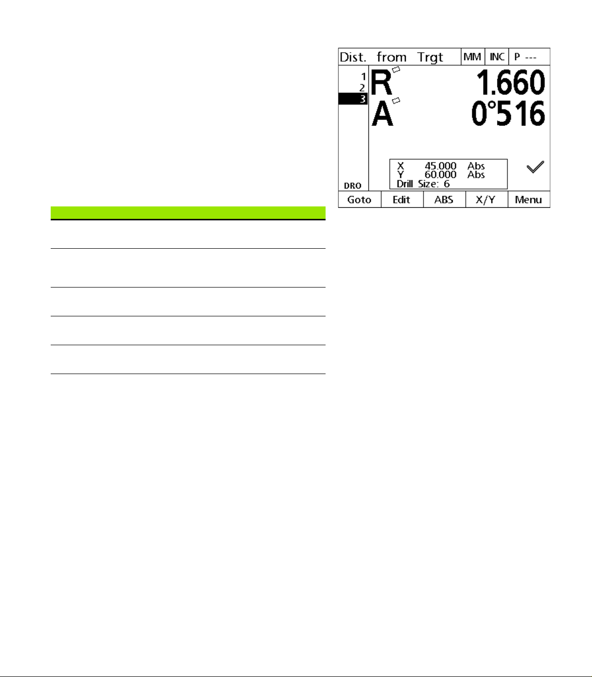
Distance from target mode screen and soft keys
The Distance from target screen shows:
List of targets on the left side
Unit of measure, current datum and program in the upper right
corner
The the distance from a target position
Part alignment status: a small rectangle over the axis letter indicates
that the part is aligned to a measurement axis (a skew was
performed)
Soft key functions for target selection, editing a target, absolute or
incremental distance selection, cartesian or polar coordinates
selection and menu access
DRO soft keys Function
Goto Press the GOTO soft key to select a target to
Edit Press the EDIT soft key to access the target
INC or ABS Toggles between incremental and absolute
1.2 Basic Functions of the ND 1200R
R/A or X/Y Toggles between cartesian and polar
Menu Press the MENU soft key to access program,
navigate to.
editing screen and edit the coordinates of the
selected target.
distances.
coordinates.
datum, pattern and setup menus.
Distance from target screen showing the distance
from the current position to the target position
18 1 Operation
Page 19
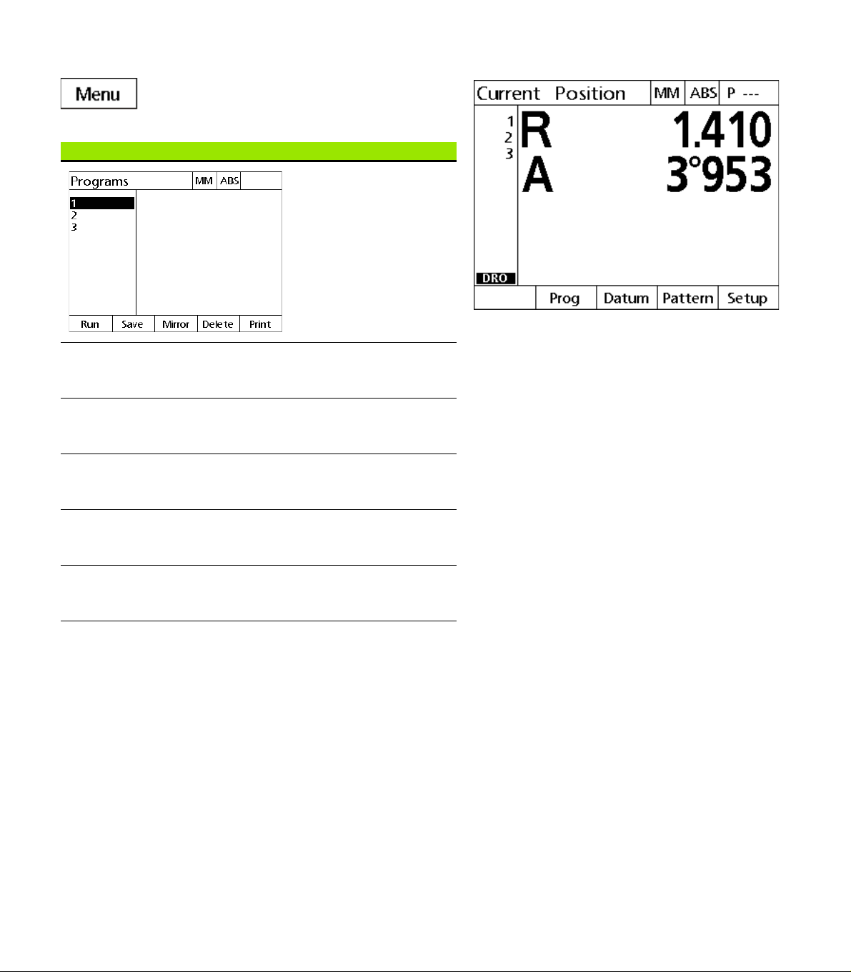
ND 1200R Menus
Press the MENU soft key to display menu titles over
the soft keys at the bottom of the LCD screen. Press
a menu soft key to display the corresponding menu
screen. Menus include:
PROGRAMS menu PROGRAMS functions
Press the PROG soft key to
display the PROGRAMS
screen and soft keys for
program functions. Soft
keys include:
Run Press the RUN soft key to
play a program of recorded
target positions.
Save Press the SAVE soft key to
save a program that can be
played back later.
Menu titles are displayed over soft keys at the bottom
of the LCD screen
1.2 Basic Functions of the ND 1200R
Mirror Press the MIRROR soft key
Delete Press the DELETE soft key
Print Press the PRINT soft key to
to mirror and run a
program.
to delete the selected
program.
transmit a program to a
computer or a USB printer.
ND 1200R Radial 19
Page 20
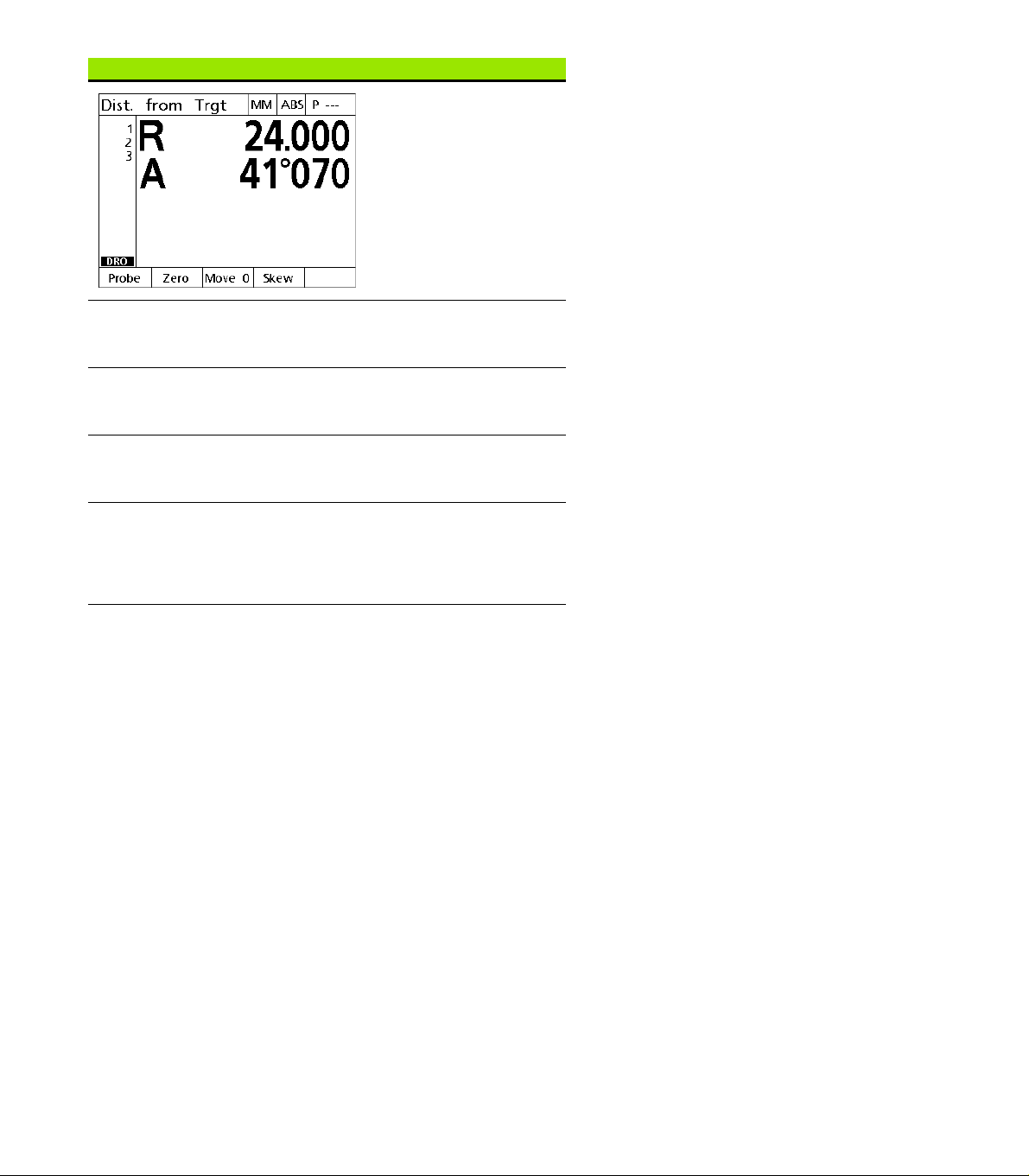
DATUM menu DATUM functions
Press the DATUM soft key
to display soft key
selections for zeroing,
moving and skewing the
datum. Soft keys include:
Probe Press the PROBE soft key
to enter the probe diameter
using the numeric keypad.
Zero Press the ZERO soft key to
select an axis, axes or hole
for zeroing the datum.
Move 0 Press the MOVE 0 soft key
to move the datum to a
new location.
Skew Press the SKEW soft key to
1.2 Basic Functions of the ND 1200R
compensate electronically
for non-square part
alignment on the primary
axis.
20 1 Operation
Page 21
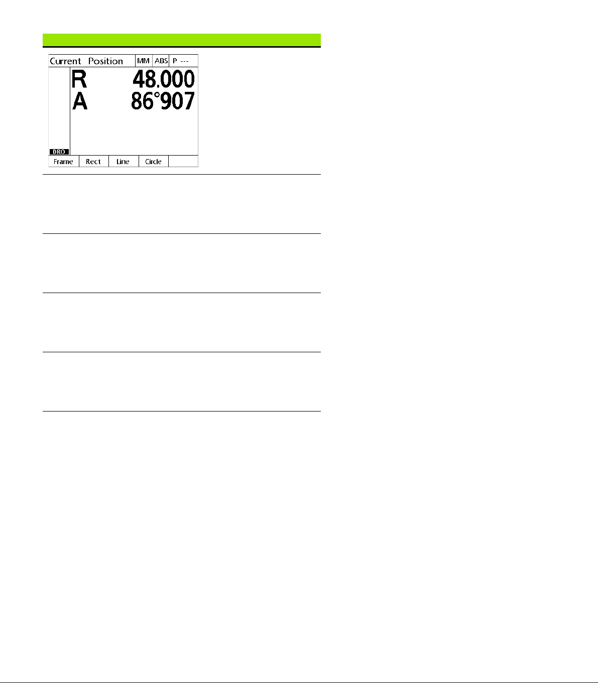
PATTERN menu PATTERN functions
Press the PATTERN soft
key to select a drilling
pattern. Soft keys include:
Frame Press the FRAME soft key
to enter the parameters to
define a frame drilling
pattern. Refer to "Frame
pattern” on page 38
Rect Press the RECT soft key to
enter the parameters to
define a rectangle drilling
pattern. Refer to "Rectangle
pattern” on page 39
Line Press the LINE soft key to
enter the parameters to
define a line drilling pattern.
Refer to "Line pattern” on
page 40
Circle Press the CIRCLE soft key
to enter parameters to
define a circle drilling
pattern. Refer to "Circle
pattern” on page 41
1.2 Basic Functions of the ND 1200R
ND 1200R Radial 21
Page 22
SETUP menu SETUP functions
Press the SETUP menu
soft key to display the
collection of SETUP
screens used to configure
the ND 1200R. Use of the
setup menu is explained in
Chapter 2: Installation,
Setup and Specifications.
Access to setup menu configuration data fields is
password restricted to supervisors and other technically
qualified personnel. Configuration mistakes can result in
serious measurement errors.
1.2 Basic Functions of the ND 1200R
22 1 Operation
Page 23

1.3 Preparing to drill
Power-up the ND 1200R
Switch on the ND 1200R. The POWER switch is located on the rear
of the enclosure. After switching the power on, or after a power
failure, the power-up screen will be displayed. See "Switching on the
ND 1200R" on page 13.
Press the FINISH key to advance from the power-up screen to the
DRO.
If your ND 1200R was configured to establish a machine zero upon
powering up, a message will be displayed asking you to cross
reference marks or specify axis references manually.
Establish machine zero
A repeatable machine zero is required for the DRO to apply the
calibration chart to the machine geometry correctly.
It is not recommended to use the machine without active
calibration. This would lead to unknown position errors.
Usually the calibration is based on referencing via reference marks on
the encoders. To establish the machine zero after power-up:
Move the stage to have the reference mark crossings recognized on
each axis.
If the machine zero is determined via hard stops:
Move the stage to the hard-stop reference position and press
ENTER on each axis.
1.3 Preparing to drill
ND 1200R Radial 23
Page 24
Adjust LCD screen contrast
+/-0
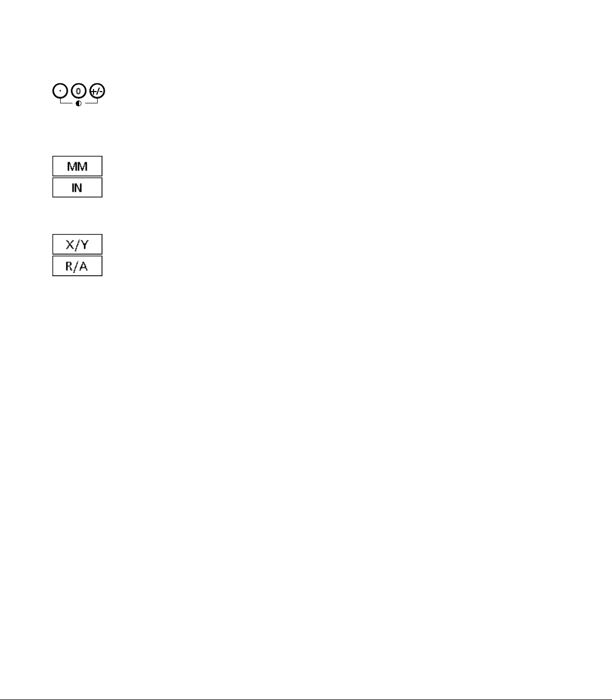
If necessary, adjust the LCD screen contrast using the decimal point
and +/- keys located on the numeric keypad.
Press the DECIMAL POINT key to increase the
contrast.
Press the +/- key to decrease the contrast.
Select unit of linear measure
Press the MM or IN soft key to toggle between
millimeters and inches.
1.3 Preparing to drill
Select a coordinate system
Press the X/Y or R/A key to toggle between cartesian
and polar coordinate systems.
24 1 Operation
Page 25
Probing a position
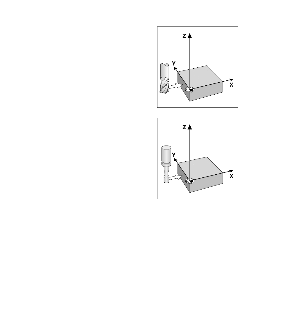
A position can be probed with a hard probe or a touch probe.
To probe a point with a hard probe:
Touch the edge of the workpiece with the probe.
Press the ENTER key.
Enter the probe diameter.
Press the ARROW key that indicates the probe compensation
direction.
To probe a point with a touch probe:
Touch the edge of the workpiece with the probe. The point and the
direction of probing will be entered automatically.
1.3 Preparing to drill
Probing a position with a hard probe
Probing a position with a touch probe
ND 1200R Radial 25
Page 26

Select a probe diameter
A probe is required to zero the axes on a workpiece. The diameter of
the probe can be adjusted. This is needed to compensate for the
offset of the part from the edge of the probe being used.This diameter
is either the diameter of the touch probe or hard probe being used.
To assign a probe diameter:
Press the DATUM soft key.
Press the PROBE soft key.
Enter the probe size.
Press the FINISH key.
1.3 Preparing to drill
26 1 Operation
Page 27
Aligning the part to an axis
1
2
3
Accurate drilling requires the part to be perfectly aligned along an axis.
Misaligned parts result in targeting errors. Use the SKEW function to
convert machine coordinates to part coordinates and compensate for
part misalignment. Perform a skew each time a new part is mounted.
Measure a skew line by probing a straight edge of the part on a major
measurement axis or by probing two or more pre-drilled holes.
The skew alignment edge or line must be oriented within
45 degrees of the measurement axis.
Aligning a part edge to an axis
To align a part edge to an axis:
Align the part on the stage.
Press DATUM>SKEW.
Probe a minimum of two points along a part edge. In the example
shown here, the part is aligned to the X-axis by probing three points
along the bottom edge of the part.
Press the FINISH key.
The part could alternately have been aligned along a
vertical edge to the Y-axis.
The orientation of the cartesian coordinate system
depends on the type of machine. It can be changed by the
supervisor (password required).
1.3 Preparing to drill
Three points are probed to align the bottom edge of a
part to the X-axis
ND 1200R Radial 27
Page 28
Aligning a pair of holes to an axis
1
2
3
4
5
6
There are certain times when the part needs to be aligned on the
center of two pre-drilled holes.
To align a pair of holes to an axis:
Align the part on the stage.
Press DATUM>SKEW>HOLE.
Probe a minimum of three points around the edge of the first hole
to be used in the skew.
Press the FINISH key to complete the first hole measurement.
Press the HOLE soft key.
Probe a minimum of three points around the edge of the second
hole to be used in the skew.
1.3 Preparing to drill
Press the FINISH key to complete the second hole measurement.
Press the FINISH key to complete the skew.
Distributing the probed points evenly around the
circumference of the hole will provide a more accurate
placement for the center of the hole.
Three points are probed for each hole to align the
center of the holes with the X-axis
28 1 Operation
Page 29
Establish a datum
1
2
3
4
1
2
3
A datum can be created from a probed point, the center point of a
probed hole or a point created from the intersection of the skew
alignment line and another line perpendicular to the skew alignment
line.
Setting a datum from a probed point
To set the datum from a probed point:
Press DATUM>ZERO>XY.
Probe the desired location of the datum.
Setting a datum from a skew line
The first point of a skew line is automatically set as the datum. The
datum is most commonly created from a point that is the intersection
of the skew alignment line and a second part edge line.
To set the datum from a skew line:
Perform a skew alignment.
Press DATUM>ZERO.
Press the soft key for the axis to zero along (the same axis used for
the skew line).
Probe a point on the part edge perpendicular to the skew line. The
datum is now set to the intersection of the skew alignment line and
the probed part edge.
Setting a datum on the center of a hole
The center of a hole is found by probing a minimum of three points on
the edge of the hole.
To set the datum from the center of a hole:
Press DATUM>ZERO>HOLE.
Probe a minimum of three points around the edge of the hole.
Press the FINISH key.
1.3 Preparing to drill
A skew is performed along the bottom and a point is
probed on the side perpendicular to the skew line
Distributing the probed points evenly around the
circumference of the hole will provide a more accurate
placement for the center of the hole.
A minimum of three points is probed around the edge
of a hole
ND 1200R Radial 29
Page 30

Moving a datum
If the datum of the part is not reachable by a probe it can be moved by
entering the coordinates from a point that has been probed.
To move the datum:
Press DATUM>MOVE 0.
Enter the X distance in relationship to the probed datum point.
Press the ENTER key.
Enter the Y distance in relationship to the probed datum point.
Press the FINISH key.
1.3 Preparing to drill
30 1 Operation
Page 31

1.4 Targets
Entering a target
The ND 1200R allows simple entry of target position coordinates. As
target position coordinates are entered a target list is created. The
target list is shown on the left side of the LCD screen.
Entering an absolute target position
To enter an absolute target position:
Press the X axis key.
Enter the X coordinate for the target.
Press the ENTER key.
Enter the Y coordinate for the target.
Press the FINISH key.
1.4 Targets
Target list shown on left side of screen
Enter the X coordinate for the target Enter the Y coordinate for the target
ND 1200R Radial 31
Page 32

Optional: Prior to pressing the FINISH key a drill diameter may be
entered. The diameter is for user reference only and does not effect
target position calculation.
Press the ENTER key.
Enter the drill diameter.
Press the FINISH key.
1.4 Targets
Optional: Enter the drill bit diameter The new target is added to the target list
and the Dist from Trgt screen is
displayed
32 1 Operation
Page 33

Entering an incremental target position
To enter an incremental target position:
Press the X axis key.
Enter the X coordinate for a new target relative to a previously
entered target.
Press the ABS/INC soft key to toggle to incremental mode.
Enter the number of the previously entered target.
Press the ENTER key.
1.4 Targets
Enter the X coordinate for the new target
relative to a previously entered target
Press the ABS/INC soft key to toggle to
incremental mode
Enter the number of the previously
entered target
ND 1200R Radial 33
Page 34

Enter the Y coordinate for the new target relative to a previously
entered target.
Press the ABS/INC soft key to toggle to incremental mode.
Enter the number of the previously entered target.
Press the FINISH key.
Optional: Prior to pressing the FINISH key a drill diameter may be
entered. The diameter is for user reference only and does not effect
1.4 Targets
target position calculation.
Press the ENTER key.
Enter the drill diameter.
Press the FINISH key.
Enter the Y coordinate for the new target
relative to a previously entered target
Press the ABS/INC soft key to toggle to
incremental mode
Enter the number of the previously
entered target
34 1 Operation
Page 35

Editing and clearing targets
Editing a target
To edit a target:
Use the UP and DOWN ARROW keys to select a target in the target
list.
Press the EDIT soft key. The Target Edit screen is displayed.
To edit target position coordinates, follow the previous instructions
for entering a target position.
Deleting a target
To delete a target:
Use the UP and DOWN ARROW keys to select a target in the target
list.
Press the CANCEL key. A message on the LCD screen will ask “Are
you sure you would like to delete this target?”.
Press the YES soft key.
1.4 Targets
Target Edit screen
Clearing the target list
To clear the target list:
Press the LCD ON/OFF key. A message on the LCD screen will
advise “The display will be turned of in 15 seconds or you may press
one of the below soft keys to clear targets and datums.”
Press the CLEAR soft key.
Deleting a target from the target list
ND 1200R Radial 35
Page 36

Marking a target
Positions in the target list can be marked with a checkmark in order to
identify the target for a future machining operation.
To mark a target:
Use the UP and DOWN ARROW keys to select a target in the target
list.
1.4 Targets
Press the AXIS key next to the checkmark symbol to mark a target.
Target marked for future machining operation
36 1 Operation
Page 37

1.5 Target patterns
Target patterns allow a way to quickly create targets by entering
parameters for target coordinates arranged in one of four patterns.
Available patterns are:
Frame
Rectangle
Line
Circle
1.5 Target patterns
ND 1200R Radial 37
Page 38

Frame pattern
Y
X
A
XD
YD
To create a Frame pattern:
Press MENU>PATTERN>FRAME.
Use the UP and DOWN ARROW keys to navigate between
parameter data fields and enter the parameter values required for
the pattern.
Press the FINISH key. The targets in the pattern are added to the
Target list and the Current Position screen is shown.
Press the FINISH key again to navigate to the first target in the
pattern.
1.5 Target patterns
Parameter Description
Start X X axis coordinate for the center of the
first hole in the pattern.
Start Y Y axis coordinate for the center of the
first hole in the pattern.
Num of Col Number of columns in the pattern.
Num of Row Number of rows in the pattern.
X Distance Distance between the center of each
hole along the X axis prior to an angle
being applied to the pattern.
Y Distance Distance between the center of each
hole along the Y axis prior to an angle
being applied to the pattern.
Angle of Array Angle applied to the pattern in relation to
the X axis.
Drill Diameter Diameter of the drill.
Frame pattern screen
Frame pattern
38 1 Operation
Page 39

Rectangle pattern
Y
X
A
XD
YD
To create a Rectangle pattern:
Press MENU>PATTERN>RECT.
Use the UP and DOWN ARROW keys to navigate between
parameter data fields and enter the parameter values required for
the pattern.
Press the FINISH key. The targets in the pattern are added to the
Target list and the Current Position screen is shown.
Press the FINISH key again to navigate to the first target in the
pattern.
Parameter Description
Start X X axis coordinate for the center of the
first hole in the pattern.
Start Y Y axis coordinate for the center of the
first hole in the pattern.
Num of Col Number of columns in the pattern.
Num of Row Number of rows in the pattern.
X Distance Distance between the center of each
hole along the X axis prior to an angle
being applied to the pattern.
Y Distance Distance between the center of each
hole along the Y axis prior to an angle
being applied to the pattern.
Angle of Array Angle applied to the pattern in relation to
the X axis.
Drill Diameter Diameter of the drill.
1.5 Target patterns
Rectangular pattern screen
Rectangular pattern
ND 1200R Radial 39
Page 40

Line pattern
Y
X
A
HD
To create a Line drill pattern:
Press MENU>PATTERN>LINE.
Use the UP and DOWN ARROW keys to navigate between
parameter data fields and enter the parameter values required for
the pattern.
Press the FINISH key. The targets in the pattern are added to the
Target list and the Current Position screen is shown.
Press the FINISH key again to navigate to the first target in the
pattern.
1.5 Target patterns
Parameter Description
Start X X axis coordinate for the center of the
first hole in the pattern.
Start Y Y axis coordinate for the center of the
first hole in the pattern.
Num of Holes Number of holes in the pattern.
Hole Dist. Distance between the center of each
hole along the X axis prior to an angle
being applied to the pattern.
Angle of Line Angle applied to the pattern in relation
to the X axis.
Drill Diameter Diameter of the drill.
Line pattern screen
Line pattern
40 1 Operation
Page 41

Circle pattern
Y
X
A
D
To create a Circle pattern:
Press MENU>PATTERN>CIRCLE.
Use the UP and DOWN ARROW keys to navigate between
parameter data fields and enter the parameter values required for
the pattern.
Press the FINISH key. The targets in the pattern are added to the
Target list and the Current Position screen is shown.
Press the FINISH key again to navigate to the first target in the
pattern.
Parameter Description
Center X X axis coordinate for the center of the
pattern.
Center Y Y axis coordinate for the center of the
pattern.
Diameter Diameter of the circle for the pattern.
Num of Holes Number of holes in the pattern.
Angle of 1st Hole Angle applied to the first hole in the
pattern in relation to the X axis.
Drill Diameter Diameter of the drill bit.
1.5 Target patterns
Circle pattern screen
Circle pattern
ND 1200R Radial 41
Page 42

1.6 Target programs
Target programs permit the user to save and run target list sequences
for later use. This allows the user to switch between workpieces and
programs without having to re-enter target coordinates.
Target programs can be:
Saved
Run
Mirrored
Printed
1.6 Target programs
Deleted
Saving a program
To save a target program:
Create a target sequence.
Press MENU>PROG>SAVE.
Enter a number for the program. A maximum of 12 digits may be
used for the number.
Press the OK soft key.
Create a target list Press MENU>PROG>SAVE Enter a program number and press the
OK soft key
42 1 Operation
Page 43

Running a program
To run a target program:
Press MENU>PROG.
Use the UP and DOWN ARROW keys to select a program.
Press the RUN soft key. The Distance to Target screen is displayed
and the program number is displayed in the upper right corner of the
screen.
1.6 Target programs
Press MENU>PROG, select a program
and press the RUN soft key
The Distance from Target screen is
displayed
ND 1200R Radial 43
Page 44

Mirroring a program
To mirror a target program:
Press MENU>PROG.
Use the UP and DOWN ARROW keys to select a program.
Press the MIRROR soft key.
Press the AXIS key for the axis to mirror the program along. The
DIstance from Target screen is displayed.
1.6 Target programs
Press MENU>PROG and select a
program
Press the MIRROR soft key Press an axis key to select an axis to
mirror along
44 1 Operation
Page 45

Deleting a program
To delete a target program:
Press MENU>PROG>.
Use the UP and DOWN ARROW keys to select a program.
Press the DELETE soft key.
Press the YES soft key to confirm program deletion.
1.6 Target programs
Press MENU>PROG and select a
program
Press the DELETE soft key and the YES
soft key to confirm program deletion
ND 1200R Radial 45
Page 46

1.7 Navigating to a target
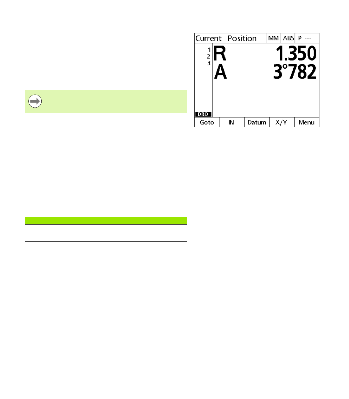
The ND 1200R displays all entered target positions as an R (radius) and
A (angle) distance from the current position. Navigating to a target is
accomplished by moving the drill head to zero directly above the
desired target position. This is for either direct targeting or from the
Pattern function.
To navigate to a target:
Select a target. The Distance from Target screen is displayed.
Move the tool in or out along the R axis until the R display reads zero.
Rotate the radial arm until the A display reads zero. The tool is now
positioned above the center of the target.
Lock the drill head and drill the hole.
1.7 Navigating to a target
Move the tool in or out until the R axis
reads zero
It is important to zero the R axis first. If the A axis is zeroed
first and the tool is moved in or out along the R axis, the
zero on the A axis will be lost.
Move the radial arm until the A axis reads
zero
46 1 Operation
Page 47

Installation, Setup and Specifications
Page 48

2.1 ND 1200R Shipment Contents
The contents of your ND 1200R shipment are described below.
Repackaging instructions are also included for return shipments for
distributors and OEM customers that are configuring a ND 1200R and
shipping it to an end-user.
Save the ND 1200R packaging materials for possible
return shipment or shipment to an end-user.
Items included with the ND 1200R
The following items are shipped with the ND 1200R:
ND 1200R instrument
Mounting stand hardware
Power cord
ND 1200R Quick reference guide
Warranty registration card
2.1 ND 1200R Shipment Contents
Optional items possibly included
The following items might be shipped with your ND 1200R, depending
on the options and accessories ordered at the time of purchase:
Remote foot switch
Remote keypad
ND 1200R Protective cover
QC-Wedge communication software
If any components were damaged in shipment, save the
packaging materials for inspection and contact your
shipping agent for mediation. Contact your Heidenhain
distributor or OEM for replacement parts.
48 2 Installation and Specifications
Page 49

Repackaging the ND 1200R
When shipping the ND 1200R on to an end-user, repackage all
ND 1200R components in the original packaging as received from the
factory.
The original packaging must be duplicated and the LCD
must be inserted face-up to prevent damage to the
screen.
It is not necessary to ship the mounting stand and
hardware with the instrument when returning the
ND 1200R for service.
Connect the mounting screws and washer to the ND 1200R
instrument.
Replace the contents of the cardboard box insert if shipping the
ND 1200R on to an end-user. The cardboard box can be empty if
returning the ND 1200R to the factory for service.
Repackage the instrument, foam and cardboard box insert as
originally shipped from the factory. The instrument should be
oriented face-up in the carton.
Replace the warranty card and slip sheets originally found at the top
of the carton when shipping on to an end-user. The “Before you
begin” slip sheet should be inserted last.
2.1 ND 1200R Shipment Contents
ND 1200R Radial 49
Page 50

2.2 Hardware Installation
5
4
3
2
1
The ND 1200R is easy to install. This section describes how to install
the ND 1200R hardware.
Assembling the mounting stand
The ND 1200R is secured to the swivel slots of the mounting stand by
a shoulder screw, a cap screw and associated washers.
Assemble the ND 1200R to the mounting stand as shown on the
right
Tighten the shoulder screw (1).
Tighten the cap screw (5) and washers (3 & 4) enough so that the
ND 1200R will be secure when adjusted to the desired tilt position.
Adjust the ND 1200R to the desired tilt position.
2.2 Hardware Installation
Complete tightening the cap screw (5) to secure the ND 1200R.
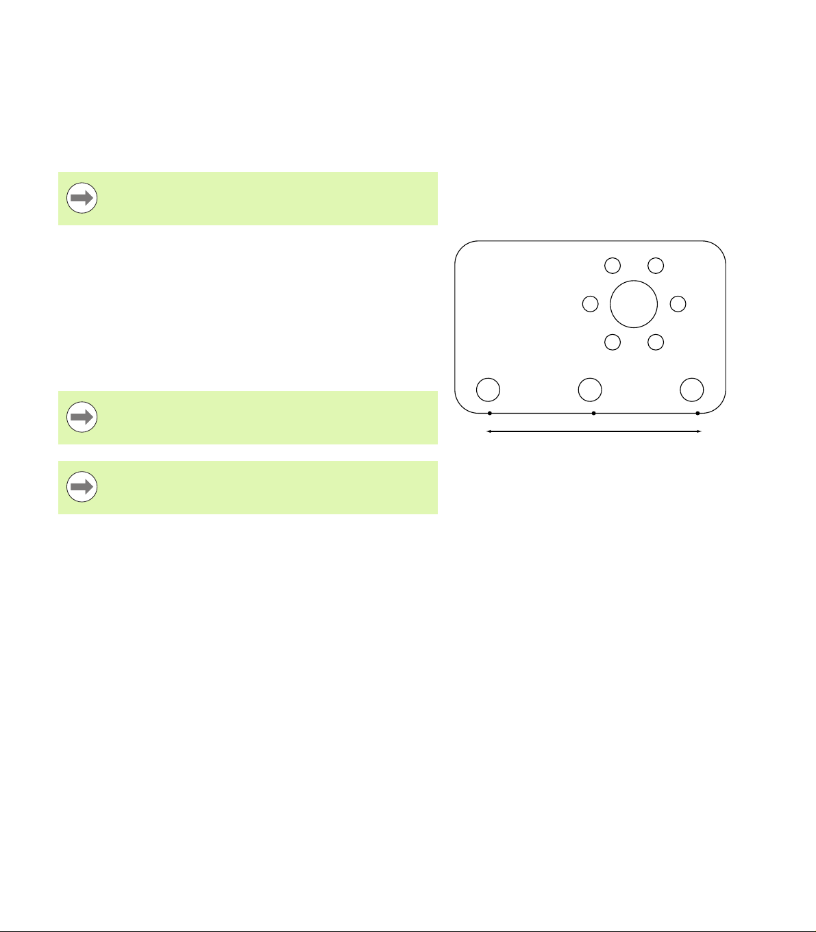
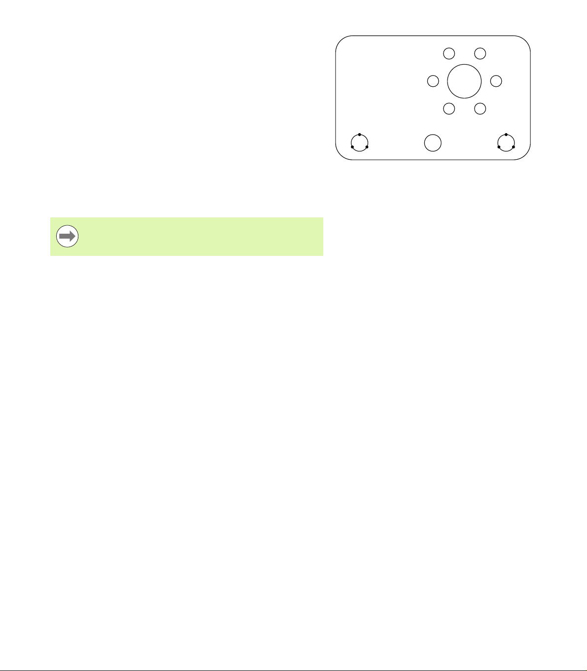
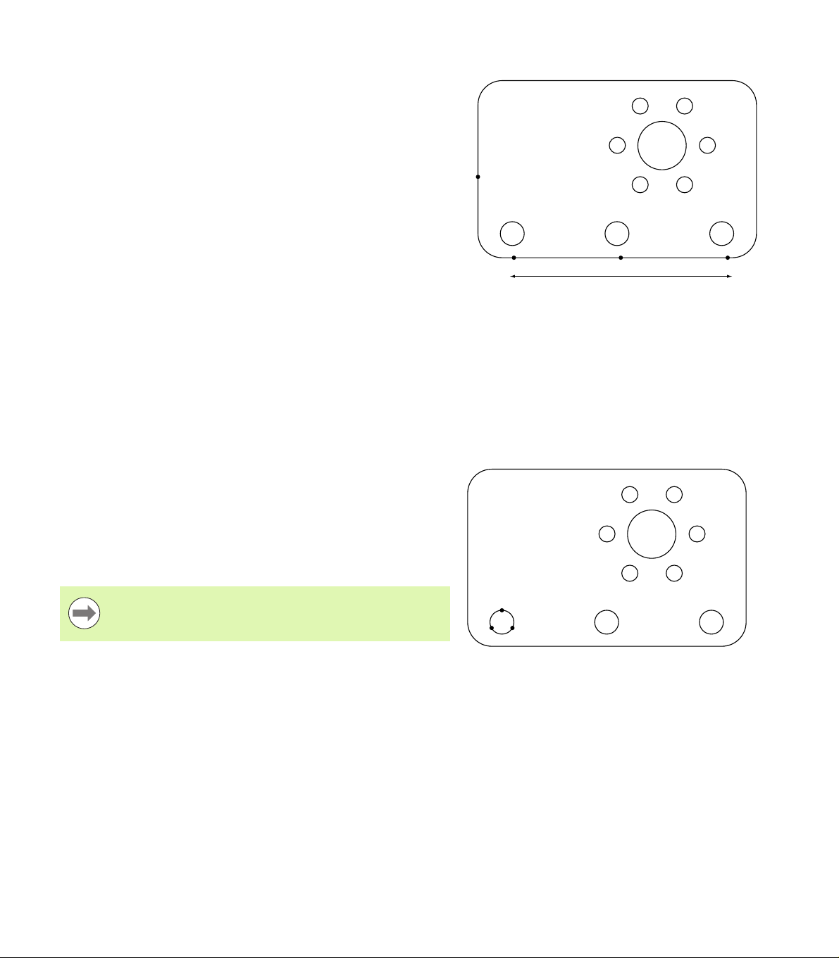
Benchtop location and mounting
Rest the ND 1200R on a flat, stable surface, or bolt it to a stable
surface from the bottom using four 10/32 screws fastened in the
pattern shown at the right.
The dimensions are shown in millimeters.
Mounting stand assembly
Mounting hole pattern
50 2 Installation and Specifications
Page 51

Arm mounting (optional)
Secure the arm mount adapter to the ND 1200R and bolt the adapter
and ND 1200R to the arm as shown at the right.
2.2 Hardware Installation
Optional arm mounting
ND 1200R Radial 51
Page 52

Connecting power
1
2
1
3
Connect the ND 1200R to power through a high-quality power surge
suppressor. Surge suppressors limit the amplitude of potentially
damaging power line transients caused by electrical machinery or
lightning, and protect the ND 1200R from most power line transients
that can corrupt system memory or damage circuits.
Do not locate the power cord where it can be walked on or will create
a tripping hazard. Connect the 3-wire power plug to only a 3-wire
grounded power outlet.
Never connect 2-wire to 3-wire adapters to the power cord
or remove the third ground wire to fit the plug into a 2-wire
electrical outlet. Modifying or overriding the third-wire
ground creates a safety hazard and should not be
permitted.
The power connector assembly includes:
2.2 Hardware Installation
1 Power switch
2 Fuse compartment
3 Power cord connector
Always disconnect the power cord from the source of AC
power before unplugging it from the ND 1200R power
connector. The AC voltage available at electrical outlets is
extremely dangerous and can cause serious injury or
death.
Power switch, fuse and connector
52 2 Installation and Specifications
Page 53

Connecting encoders and probes
142
3
Axis encoders and probes are attached to interface connectors on the
rear of the ND 1200R. Many encoder interfaces are available to match
the wide variety of encoders that can be used with the ND 1200R. The
type and number of axis encoder connectors will vary depending on
the application. The ND 1200R shown in this photo includes
connectors for the X, Y and Z axes and a touch probe. Encoder inputs
are specified as analog or TTL at the time of purchase and cannot be
changed in the field.
Do not locate encoder cables where they can be walked
on or will create a tripping hazard.
The encoder connector locations are:
1 X-axis
2 Y-axis
3 Z-axis
4 Touch probe
To connect the encoder cables and probe:
Verify that the ND 1200R is off.
Connect the axis encoders tightly to their connectors. An axis label
is provided near each connector. If the connectors include mounting
screws, do not overtighten them.
Encoder axis connectors
2.2 Hardware Installation
ND 1200R Radial 53
Page 54

Connecting a computer
1
Measurement result data can be sent to a computer over the RS-232
port (1) using a serial cable that does not include crossed wires. To
connect a computer:
Verify that the ND 1200R and the computer power are off.
Connect a computer COM port to the ND 1200R RS-232 serial port
(1) using a standard straight-through serial cable. Make sure the
cable connectors are tight, but do not overtighten the connector
screws.
Apply power to the computer, and then the ND 1200R. The
ND 1200R default settings for communication over the RS-232
serial port (1) are:
Baud rate 115,200
Word length 8 bits
2.2 Hardware Installation
Stop bits 1 bit
Parity None
Launch the computer application that will be used to communicate
with the ND 1200R, and configure the communication properties of
the COM port to match those of the ND 1200R.
RS-232 connector
54 2 Installation and Specifications
Page 55

Connecting a headphone
1
2
Audio alerts can be sent to headphones in areas that are noisy and
make it difficult to hear, or are quiet where audio alerts might create a
disturbance.
The speaker jack (1) is located on the side of the ND 1200R.
To connect headphones:
Verify that the ND 1200R power is off. Plug the headphones into the
speaker jack (1) on the side of the enclosure.
Make sure the headphone plug is fully inserted.
Connecting a USB printer
The ND 1200R supports certain USB printers. Printer models are
specified by Heidenhain at the time of purchase, or approved by
Heidenhain later.
The USB port (2) is located on the side of the ND 1200R.
To connect a USB printer:
Verify that the ND 1200R and printer power are off. Connect the
USB printer to the USB Type A port (2) on the side of the enclosure.
Make sure the USB cable plug is fully inserted.
Headphone, USB connectors
2.2 Hardware Installation
ND 1200R Radial 55
Page 56

Connecting an optional foot switch or remote
1
2
keypad
The optional foot switch and remote keypad are connected to the
RJ-45 connector on the side of the ND 1200R.
Often, only the optional foot switch or remote keypad is used.
However, two options can be connected simultaneously using a RJ-45
splitter.
The RJ-45 connector and splitter are shown here:
1 RJ-45 connector
2 RJ-45 splitter
RJ-45 splitters are available from most retail electronics
stores.
2.2 Hardware Installation
The foot switch and remote keypad can be used individually or in
combination:
foot switch
remote keypad
foot switch and remote keypad
When the foot switch and remote keypad are connected using the
RJ-45 splitter, all operating functions of each device are retained.
However, the switch shares Hot Key mapping with the number keys
7 and 8 of the remote keypad. As a result, functions assigned to the
two switch contacts will also be mapped to remote keypad numbers
7 and 8.
RJ-45 connector and RJ-45 splitter
Hot keys are discussed later in this chapter under
Software setup/Hotkeys. See "Hot key assignments" on
page 76.
To connect the foot switch or remote keypad:
Verify that the ND 1200R is off.
Plug an RJ-45 splitter into the ND 1200R RJ-45 connector if multiple
devices will be used.
Connect the RJ-45 plug of the devices into the RJ-45 splitter if
multiple devices will be used, or directly into the ND 1200R RJ-45
connector if only a single device will be used.
56 2 Installation and Specifications
Optional foot switch and remote keypad
Page 57

2.3 Software setup
The operating parameters of the ND 1200R must be configured prior
to using it for the first time, and any time drilling or communication
requirements change. Day to day use of the ND 1200R does not
require reconfiguration of software settings.
Parameter changes made in any of the setup screens can
change the operation of the ND 1200R. For this reason,
setup parameters are password-protected. Only qualified
personnel should be given password access to setup
screens. The unlocking of password-protected setup
functions is described on page 63.
Software is configured manually using the setup menu screens.
Parameters configured in setup screens will be retained until:
The data-backup battery is changed
The data and settings are cleared by maintenance personnel
Parameters are changed using the setup menu screens
Certain software upgrades are performed
2.3 Software setup
ND 1200R Radial 57
Page 58

Setup menu
1
2
3
Most operating parameters of the ND 1200R are configured using
screens and data fields accessed from the setup menu. Highlighting
setup menu items on the left side of the setup screen displays the
corresponding setup parameter data fields and choice fields on the
right side of the screen.
1 Setup menu item: Setup screen name
2 Setup data field: Setup data are entered
3 Setup choice field: Setup choices are made
The setup menu is easy to use:
2.3 Software setup
Press the MENU soft key and then press the SETUP soft key.
Navigate up or down in the menu to highlight the desired menu item
using the UP/DOWN ARROW keys.
Navigate from the menu (left side) to the setup fields (right side)
using the LEFT/RIGHT ARROW keys.
Navigate up or down to highlight the desired data or choice field
using the UP/DOWN ARROW keys.
Enter setup data using the NUMERIC KEYPAD, or choose a setup
parameter choice from soft key selections or list shown when the
field is highlighted.
Press the FINISH key to save the entry and return to the setup
menu.
Press the FINISH key again to return to the DRO.
An example of using the setup menu to enter the supervisor password
is shown on the next page.
Setup screen menu items, data fields and choice
fields
58 2 Installation and Specifications
Page 59

Setup example: entering the supervisor password
Critical setup parameters are password-protected. Only qualified
personnel should be given password access to setup screen
parameters. In this example, the setup menu is navigated to the
Supervisor screen and the supervisor password is entered.
To enter the supervisor password:
Press the MENU soft key to display the menu soft keys.
Press the SETUP soft key to display the setup menu.
Navigate up or down in the menu to highlight the Supervisor menu
item using the UP/DOWN ARROW keys.
2.3 Software setup
The MENU soft key is pressed to display
the menu soft keys
The SETUP soft key is pressed to display
the setup menu
The UP/DOWN ARROW keys are used
to highlight the Supervisor menu item
ND 1200R Radial 59
Page 60

Navigate from the menu to the Password setup field using the
RIGHT ARROW key.
Enter the supervisor password using the NUMERIC KEYPAD.
2.3 Software setup
The RIGHT ARROW key is used to
highlight the Password data field
Press the FINISH key to save the password and return to the setup
The supervisor password is entered
using the NUMERIC KEYPAD
menu.
Press the FINISH key to return to the DRO.
The FINISH key is pressed to save the
password and return to the setup menu
60 2 Installation and Specifications
Page 61

Order of setup
The ND 1200R setup software is contained on up to 12 screens,
depending on the hardware configuration. It is possible that not all the
setup screens described in this chapter are active in your system.
Disregard screen descriptions that do not apply to your ND 1200R.
The initial ND 1200R setup tasks should be performed in the order
listed here. Instructions are presented in this order on subsequent
pages.
Initial setup tasks Setup screens
1: Language selection and product version information About
2: Supervisor password entry and program unlocking Supervisor
3: Encoder configuration Encoders and Misc
4. Touch probe configuration Radial
5: Error correction LEC
6: Display formatting Display
The additional setup tasks can be performed in any order.
Remaining setup tasks Setup screens
Hot key assignments Hot keys
2.3 Software setup
Print formatting Print and Form characters screens
RS-232 and USB port configuration Ports
Audio volume Misc
Key repeat delay Misc
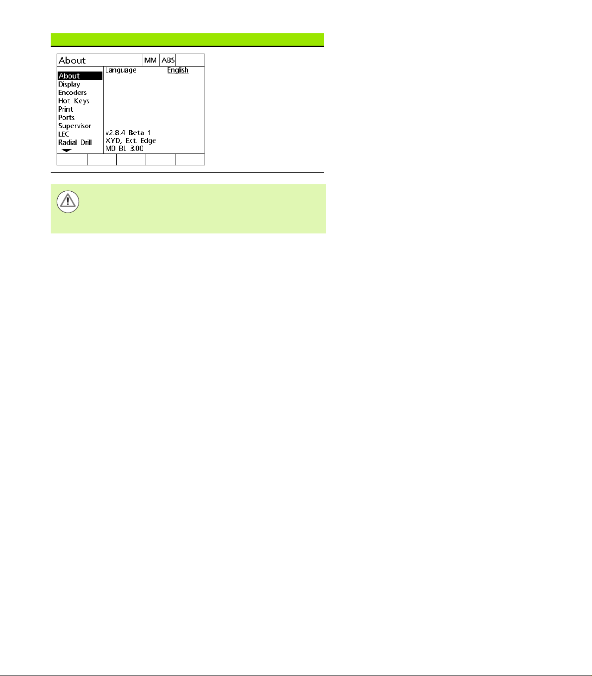
Screen saver activation Misc.
Time and date Clock
ND 1200R Radial 61
Page 62

Language selection and product version
The About screen contains selections for changing the language of
text displayed on the screen and included in transmitted or printed
data. Product software and hardware information is also provided on
the About screen.
The product software and hardware version information
will be required if technical support is needed.
To select a language:
Press MENU>SETUP to display the setup menu and highlight the
2.3 Software setup
About menu item.
Press the RIGHT ARROW key to highlight the first language
selection field.
Use the UP/DOWN ARROW keys to select the desired language.
Press the YES soft key.
Highlight the About menu item Highlight the first language selection
field
Press the FINISH key to save the language and return to the setup
Highlight a language and press the YES
soft key
menu.
62 2 Installation and Specifications
Page 63

Supervisor password
The Supervisor screen contains the Password data field and Startup
Zero choice field.
Most setup parameters are password-protected and setup can only be
performed after the password is entered. To enter the supervisor
password:
Press MENU>SETUP to display the setup menu and then highlight
the Supervisor menu item.
Highlight the Password data field.
Enter the supervisor password.
Highlight the Supervisor menu item Highlight the Password data field Enter the password
2.3 Software setup
ND 1200R Radial 63
Page 64

To enable Startup Zero:
Highlight the Startup Zero choice field.
Press the YES soft key.
2.3 Software setup
Highlight the Startup Zero choice field Press the YES soft key
Press the FINISH key to save parameters and return to the setup
menu.
64 2 Installation and Specifications
Page 65

Encoder configuration
The Encoders and Misc screens contain data and choice fields for
configuring the encoders.
Encoders screen
The Encoders screen configuration fields include:
Axis selection
Encoder resolution
Encoder type (TTL, analog or serial)
Reference mark selection
Machine zero offset (MZ Cnts)
Reversing encoder count direction
To configure encoder settings in the Encoders screen:
Press MENU>SETUP to display the setup menu and then highlight
the Encoders menu item.
Highlight the Axis choice field and then press a soft key to select the
desired axis.
The setup process for all axes is identical.
Highlight the Res data field and then enter the encoder resolution in
the units shown in the Units choice field.
2.3 Software setup
Encoders menu item is highlighted Press an axis soft key Enter the encoder resolution
ND 1200R Radial 65
Page 66

Highlight the Type choice field and then press a soft key to select
the encoder type.
Highlight the Ref Marks choice field and then press a soft key to
select the encoder reference mark type.
The M.Z. Cnts (Machine zero counts) data field is rarely used to specify
an offset from the machine zero position created by crossing encoder
reference marks.
Custom machine zeroes are rarely used because datums are always
established before performing measurements.
To specify a custom machine zero, highlight the M.Z. Cnts data field
and enter the machine zero offset in machine counts as determined
by: Machine counts = DRO value/encoder resolution.
2.3 Software setup
Select the encoder type Select an encoder reference mark type Enter machine zero offset counts if
required
66 2 Installation and Specifications
Page 67

Highlight the Reversed choice field and then press the YES soft key
to reverse the encoder count direction.
Choose a count direction
Press the FINISH key to save parameters and return to the setup
menu.
2.3 Software setup
ND 1200R Radial 67
Page 68

Misc screen
The Misc screen encoder configuration fields include:
Auto DRO counts: The number of least significant DRO counts
required to refresh the DRO with new axis values.
Slew limit for the axes: High input slew rates resulting from rapid
input encoder motion can result in erroneous measurements.
Erroneous measurements are avoided by displaying encoder error
warnings when encoder values change at very high rates.
To configure encoder settings in the Misc screen:
Press MENU>SETUP to display the setup menu and then highlight
the Misc menu item.
2.3 Software setup
Highlight the Auto DRO Cnts data field and enter the number of
DRO counts (axis motion) in the least significant digit position
required to automatically refresh the DRO axis values.
Highlight the Slew Limit data field and enter the slew rate limit
(increments of resolution per second). For example, at a channel
resolution of 0.001 mm, a slew rate limit of 50,000 will result in
warning messages at encoder motion rates higher than 50 mm per
second.
Enter Auto DRO counts Enter the slew rate limit in encoder
counts per second
Press the FINISH key to save parameters and return to the setup
menu.
68 2 Installation and Specifications
Page 69

Probe configuration
The Radial screen contains data and choice fields for configuring a
probe.
Radial screen
The Radial screen configuration fields include:
Touch probe type
Probe size
Prompts for drilling
Side operation
Probe level
Probe debounce
To configure probe settings in the Radial screen:
Press MENU>SETUP to display the setup menu and then highlight
the Radial menu item.
Highlight the Touch Probe choice field and then press a soft key to
select the probe type.
Highlight the Probe Size data field and then enter the diameter of the
probe.
Highlight the Drill Prompts choice field and then press a soft key to
select prompting for drill changes.
2.3 Software setup
Select a touch probe type Enter a probe size Select display of drill prompts
ND 1200R Radial 69
Page 70

Highlight the Side Oper choice field and then press a soft key to
select side operation.
Highlight the Probe Level choice field and then press a soft key to
select High or Low probe level.
Highlight the Prb Debounce data field and then enter the minimum
time the probe must be stable in seconds.
2.3 Software setup
Select side operation Select probe level Enter the probe debounce time in
seconds
Press the FINISH key to save parameters and return to the setup
menu.
70 2 Installation and Specifications
Page 71

Error correction
The ND 1200R provides Linear Error Correction for the R axis. LEC
compensates for encoder and machine travel variations with error
correction coefficients. Coefficients are determined by comparing
actual measurements of a standard to the nominal values
imprintedonit.
Linear error correction (LEC)
Linear Error Correction is performed in the LEC setup screen and
compensates for variations along the R axis using one correction
coefficient for the entire range of motion on the axis. For example, an
LEC coefficient of 0.0002 per inch applied to a 6 inch measurement
along an axis produces a result of 6.0012 inches. To apply LEC to the
R axis:
Press MENU>SETUP to display the setup menu.
Highlight the LEC menu item and make sure that all correction
values are 1.0.
2.3 Software setup
Press MENU>SETUP to display the
Setup menu
ND 1200R Radial 71
Highlight the LEC menu item and make
sure that all correction values are 1.0
Page 72

Position the standard artifact along the R axis.
0
0
+0.02
+0.01
0.00
-0.01
-0.02
8.0
7.98
123
4
Align the artifact as closely as possible to the axis and then perform
a skew alignment as described in chapter 1 (see "Aligning the part
to an axis" on page 27).
Perform a single measurement of the entire range of motion using
the standard artifact and make a note of the result.
Use an artifact that allows measurements of as much of
the axis range of motion as possible.
In this example of applying LEC, one point at end of the axis
measurement range is measured using an 8 inch standard.
2.3 Software setup
Arrow number Descriptions
1: Standard length Entire 8 inch length is measured
2: Standard values The certified length of the standard
3: Observed values The measured length of the standard
4: Deviation graph Difference between standard and observed
values (not entered into any screen)
LEC example using an 8 inch standard
72 2 Installation and Specifications
Page 73

To perform the linear error correction in the LEC screen:
Highlight the LEC menu item.
Enter the Standard value of the artifact and the Observed value
measured by the ND 1200R for the R axis.
The standard and observed values for axes should be
1.000 when no LEC correction is applied.
Highlight the LEC screen Enter the standard and observed values
for the R axis
Press the FINISH key to save parameters and return to the setup
menu.
2.3 Software setup
ND 1200R Radial 73
Page 74

Display formatting
The Display screen contains data and choice fields for configuring
display resolution and other display parameters.
Display screen
The Display screen configuration fields include:
Startup linear units of measure
Selection of a comma or decimal point radix
Resolutions for linear and angular measurements
To configure display settings:
2.3 Software setup
Press MENU>SETUP to display the setup menu and then highlight
the Display menu item.
Highlight the Startup Linear choice field and press a soft key to
specify a unit of linear measure set by the ND 1200R upon startup.
Soft key selections are:
Soft key Result
MM The linear unit of measure will be millimeters
Inch The linear unit of measure will be inches
Last The linear unit of measure will not be changed
Highlight the Radix choice field and press a soft key to select a
Decimal or Comma radix.
Highlight the Display menu item Specify a unit of linear measure set upon
startup
74 2 Installation and Specifications
Select a Decimal or Comma radix
Page 75

Highlight the MM Disp Res data field and enter the display
resolution index number. For example, an index number of 0.001
will round the display to 3 digits to the right of the radix character.
Highlight the Inch Disp Res data field and enter the display
resolution index number. For example, an index number of 0.001
will round the display to 3 digits to the right of the radix character.
Highlight the Angle Disp Res data field and enter the display
resolution index number. For example, an index number of 0.001
will round the display to 3 digits to the right of the radix character.
Enter the MM Display Resolution Enter the Inch Display Resolution Enter the Angle Display Resolution
Highlight the axis selection field.
Select the A axis and repeat the display resolution entry steps.
Press the FINISH key to save parameters and return to the setup
menu.
2.3 Software setup
ND 1200R Radial 75
Page 76

Hot key assignments
quit
cancel
enter
finish
+/-0
4
1
7
5 6
2 3
8 9
1
2 34
5
The Hot Keys setup screen is used to map frequently used functions
to front panel keys, remote keypad keys and foot switch keys. Hot
keys can save time by eliminating the need to navigate through menus
to initiate a function, or by making a function more accessible through
a foot switch or remote keypad.
ND 1200R keys and switches that are available for hot key mapping
are shown here:
Arrow number Descriptions
1 Wide keys
2.3 Software setup
2 Unit keys
3 Remote keys
4 Foot switch 1
5 Foot switch 2
The remote foot switch and keypad are optional
accessories that are purchased separately.
Hot keys screen
The Hot Keys screen configuration fields include:
Key type or switch type
Specific key or switch for hot key assignment
Function to assign to the key or switch
Front panel keys available for hot key mapping
Remote keys and switches available for hot key
mapping
76 2 Installation and Specifications
Page 77

To assign a function to a hot key:
Press MENU>SETUP to display the setup menu and then highlight
the Hot keys menu item.
Highlight the Keys choice field and then press a soft key to select
the desired key type or switch type. In this example the Foot switch
type is selected.
Highlight a specific key or switch. In this example foot switch 2 is
selected.
Press a soft key to select a function type to assign. In this example
a Special function will be assigned.
2.3 Software setup
Press a soft key to select a key or switch
type
Highlight a specific key or switch for
assignment
Press a soft key to select a function type
ND 1200R Radial 77
Page 78

Highlight the specific function and press the ENTER key to complete
the assignment. In this example the Zero 2 function is assigned to
foot switch 2. After the assignment, pressing foot switch 2 will zero
the X and Y axes.
2.3 Software setup
Highlight a specific function to assign Press the ENTER key to complete the
assignment
Press the FINISH key to return to the setup menu.
The functions contained in the Special menu are shown here:
Special menu function Description
DMS/DD Toggles the display of angles between degrees, minutes and seconds and decimal degrees.
Zero 2 Zeroes the X and Y axes
Send X Sends the current X-axis data to a printer or computer.
Send Y Sends the current Y-axis data to a printer or computer.
Send Z Sends the current Z-axis data to a printer or computer.
Send D Sends the current diameter data to a printer or computer.
Send 2, 3, 4 Sends the current X-Y, X-Y-Z or X-Y-Z-D axes data to a printer or computer.
Clr Datums Clears the datums
MCS Clears datums and reestablishes machine coordinates.
78 2 Installation and Specifications
Page 79

Print formatting
Print formatting data and choice fields are contained in the Print
screen.
Print screen
The Print screen configuration fields include:
Line Terminator type
Printing of axis units and labels
Sending of data via the RS-232 or USB port
Press MENU>SETUP to display the setup menu and then highlight
the Print menu item.
Highlight the Line Terminator choice field and then press a soft key
to select a carriage return (CR) or carriage return/line feed (CR/LF) to
terminate each line of data sent to a computer or printer.
Highlight the Print Axis Labels choice field and press the YES or NO
soft key to include or exclude axis labels in data sent to a computer
or printer.
2.3 Software setup
Highlight the Print menu Select a line terminator Press a soft key to enable or disable
printing of axis labels
ND 1200R Radial 79
Page 80

Highlight the Print Axis Units choice field and press the YES or NO
soft key to include or exclude axis units in data sent to a computer
or printer.
Highlight the Destination choice field and then press a soft key to
select the RS-232 or USB port to send data to.
2.3 Software setup
Press a soft key to enable or disable
printing of axis units
Press the FINISH key to return to the setup menu.
Select a destination
80 2 Installation and Specifications
Page 81

Port configuration
The Ports screen contains data and choice fields for configuring
communication parameters of the RS-232 serial port and the
USB port.
Ports screen
The Ports screen configuration fields include:
RS-232
Baud rate
Word length
Stop bits
Parity
Type of data sent on the serial port
End of character and end of line delay
USB
Type of data sent on the USB port
2.3 Software setup
ND 1200R Radial 81
Page 82

To configure ports:
Press MENU>SETUP to display the setup menu and then highlight
the Ports menu item.
Highlight the Baud choice field and then press a soft key to increase
(INC) or decrease (DEC) the baud rate.
Highlight the Word Len choice field and press a soft key to select a
7 or 8 bit word length.
Highlight the Stop Bits choice field and press a soft key to select
1 or 2 stop bits.
2.3 Software setup
Press the DEC or INC soft key to
decrease or increase the baud rate
Press a soft key to select a 7 or 8 bit
word length
Press a soft key to select 1 or 2 stop bits
82 2 Installation and Specifications
Page 83

Highlight the Parity choice field and press a soft key to select ODD,
EVEN or NONE.
Highlight the Data choice field and press a soft key to select the data
to be printed using the RS-232 port. Data choices include:
None: No data will be sent
Position: Current position
2.3 Software setup
Press the ODD or EVEN soft key to
select parity
Press the NONE or POSITION soft key to
select an RS-232 data choice
ND 1200R Radial 83
Page 84

Highlight the EOC (end of character) Delay and EOL (end of line)
Delay data fields and enter any delays in milliseconds that might be
required to optimize RS-232 communication negotiations with
external devices.
Highlight the USB Data choice field and press a soft key to select the
data to be printed using the USB port. Data choices include:
None: No data will be sent
Position: Current position
2.3 Software setup
Enter an EOC or EOL delay Press the NONE or POSITION soft key to
Press the FINISH key to return to the setup menu.
select a USB data choice
84 2 Installation and Specifications
Page 85

Audio volume
An audible beep is emitted by the ND 1200R when a front panel key
is pressed.
Misc screen
The Misc screen contains a data field for adjusting the volume of
sounds. To adjust the volume:
Press MENU>SETUP to display the setup menu and then highlight
the Misc menu item.
Highlight the Volume data field and enter a value between 0 and 10.
A value of zero will disable sounds.
Enter a value to adjust the volume
Press the FINISH key to return to the setup menu.
2.3 Software setup
ND 1200R Radial 85
Page 86

Key repeat rate adjustment
When a front panel key is pressed and held, the function repeats. The
auto-repeat rate for front panel keys can be adjusted.
Misc screen
The Misc screen contains a data field for adjusting key repeat rate. To
adjust the key repeat rate:
Press MENU>SETUP to display the setup menu and then highlight
the Misc menu item.
Highlight the Key Delay data field and enter a value between 5 and
25. Enter small values for fast repetition or large values for slow
repetition.
2.3 Software setup
Values smaller than 5 and larger than 25 can make the
keyboard difficult to use and should be avoided.
Enter a value to adjust key repeat rate
Press the FINISH key to return to the setup menu.
86 2 Installation and Specifications
Page 87

Screen saver activation
Misc screen
The Misc screen contains a data field for adjusting idle time required
prior to the activation of the screen saver. To adjust the screen saver
activation time:
Press MENU>SETUP to display the setup menu and then highlight
the Misc menu item.
Highlight the Scr Saver Min data field and enter the number of
minutes the ND 1200R is idle prior to activation of the screen saver.
The screen saver is disabled if a value of 9999 is entered.
Enter the minutes the DRO is idle prior to
screen saver activation
Press the FINISH key to return to the setup menu.
2.3 Software setup
ND 1200R Radial 87
Page 88

Time and date settings
Clock screen
The Clock screen contains data fields for setting the time and date. To
set the time and date:
Press MENU>SETUP to display the setup menu and then highlight
the Clock menu item.
The date and time are set using the same method: Highlight a date
or time data field and enter the value.
Highlight the Date Format choice field and press a soft key to select
the desired format.
Highlight the Time Format and press a soft key to select the 12 hour
2.3 Software setup
or 24 hour time format.
Enter date and time values Select a date format Select a time format
Press the FINISH key to return to the setup menu.
88 2 Installation and Specifications
Page 89

2.4 Specifications
Specifications
Axes 2 to 3 axes
Encoder inputs Linear and rotary encoders
Analog 1 V
TTL
PP
Display Black and white LCD
5.7” (14.48 cm)
0.50” (1.27 cm) display digit size
0.000004” (0.00001 mm) Resolution
Error compensation Linear (LEC)
Data interfaces Serial interfaces
RS-232-C
USB 2.0 Type A Full-speed
Optional accessories Remote foot switch
Remote keypad
ND 1200R Protective cover
QC-Wedge communication software
Main power input AC 100 V ... AC 240 V (-15 % ... +10 %)
50 Hz ... 60 Hz (±2 %)
Line fuse T1.6 A, 250 V, 5 mm X 20 mm
ENC testing EN61326: 1998 EMC for electrical equipment for measurement, control and laboratory use
EN61010: Safety requirements for electrical equipment for measurement, control and
laboratory use
2.4 Specifications
Installation category II
Environmental Temperature: 32 °F to 113 °F (0 °C to 45 °C) non-condensing
Relative air humidity: 90%
Altitude: 6562 feet (2000 meters)
Enclosure Benchtop; cast-metal enclosure
Dimensions Enclosure (W x H x D): 11.5” X 7.5” X 2.75” (29.21cm X 19.05 cm X 6.99 cm)
Base (W x H x D: 10” X 2” X 7.8” (25.4 cm X 5.8 cm X 19.81 cm)
Weight Enclosure: 3.5 lbs (1.6 kg)
Base: 7 lbs (3.2 kg)
ND 1200R Radial 89
Page 90

Dimensions
A
The ND 1200R enclosure, tray stand and arm mount bracket
dimensions are shown in the format: mm.
2.4 Specifications
90 2 Installation and Specifications
Page 91

Arm mount bracket
2.4 Specifications
ND 1200R Radial 91
Page 92

2.4 Specifications
92 2 Installation and Specifications
Page 93

A
abs soft key ... 18
absolute target, enter ... 31
align, part ... 27
arm mounting ... 51
arrow keys ... 16
B
benchtop mounting ... 50
C
circle
pattern ... 41
soft key ... 21
clear target ... 35
clock, setup ... 88
computer, connecting ... 53
connections
computer ... 53
encoder ... 53
footswitch ... 56
headphone ... 55
power ... 52
probe ... 53
remote keypad ... 56
usb printer ... 55
contrast, adjust ... 24
D
datum
establish ... 29
menu ... 20
move ... 30
soft key ... 17
delete
key ... 15
program ... 45
soft key ... 19
target ... 35
dimensions
arm mount bracket ... 91
enclosure ... 90
tray stand ... 90
display, setup ... 74
distance from target screen ... 17, 18
dro screen ... 17
E
edit
soft key ... 18
target ... 35
encoders
connecting ... 53
setup ... 65
enter key ... 15
error correction ... 71
F
finish key ... 15
footswitch, connecting ... 56
frame pattern ... 38
frame soft key ... 21
G
goto soft key ... 17, 18
H
hard probe ... 25
hardware installation ... 50
headphones, connecting ... 55
hot keys, setup ... 76
I
in soft key ... 17
inc soft key ... 18
incremental target, enter ... 33
items
included ... 48
optional ... 48
K
key repeat, setup ... 86
keys
arrow ... 16
axis ... 15
command ... 15
delete ... 15
enter ... 15
finish ... 15
lcd on/off ... 16
quit ... 15
send ... 16
wide ... 16
L
language, select ... 62
lcd
on/off key ... 16
screen ... 17
lec ... 71
line
pattern ... 40
soft key ... 21
linear error correction ... 71
M
machine zero ... 14, 23
menu soft key ... 17, 18, 19
menus
datum ... 20
pattern ... 21
programs ... 19
setup ... 22, 58
mirror
program ... 44
soft key ... 19
mm soft key ... 17
mounting
arm ... 51
benchtop ... 50
stand ... 50
move zero soft key ... 20
N
navigating to a target ... 46
O
overview ... 12
Index
ND 1200R Radial 93
Page 94

P
panel keys ... 15
part alignment ... 27
Index
align edge to axis ... 27
align holes to axis ... 28
password ... 59, 63
pattern
circle ... 41
frame ... 38
line ... 40
rectangle ... 39
pattern menu ... 21
port, setup ... 81
power
connecting ... 52
off ... 14
on ... 13, 23
preparing to drill ... 23
print
setup ... 79
soft key ... 19
probe
connecting ... 53
diameter, selecting ... 26
hard ... 25
position ... 25
setup ... 69
soft key ... 20
touch ... 25
probe a position ... 25
product version ... 62
programs ... 42
delete ... 45
menu ... 19
mirror ... 44
run ... 43
save ... 42
Q
quit key ... 15
R
r/a soft key ... 17, 18
rect soft key ... 21
rectangle pattern ... 39
remote keypad, connecting ... 56
repackaging ... 49
run
program ... 43
soft key ... 19
S
save
program ... 42
soft key ... 19
screen saver, setup ... 87
screens
distance from target ... 17, 18
dro ... 17
lcd ... 17
setup ... 17
select
coordinate system ... 24
unit of measure ... 24
send key ... 16
setup
clock ... 88
display ... 74
encoder ... 65
example ... 59
hot keys ... 76
key repeat ... 86
menu ... 22, 58
order ... 61
ports ... 81
printing ... 79
probe ... 69
screen ... 17
screen saver ... 87
software ... 57
volume ... 85
setup screens
clock ... 88
display ... 74
encoders ... 65
hot keys ... 76
misc ... 68, 85, 86, 87
ports ... 81
print ... 79
radial ... 69
shipment contents ... 48
skew soft key ... 20
S
soft keys
abs ... 18
circle ... 21
datum ... 17
delete ... 19
edit ... 18
frame ... 21
goto ... 17, 18
in ... 17
inc ... 18
line ... 21
menu ... 17, 18, 19
mirror ... 19
mm ... 17
move zero ... 20
print ... 19
probe ... 20
r/a ... 17, 18
rect ... 21
run ... 19
save ... 19
skew ... 20
x/y ... 17, 18
zero ... 20
software setup ... 57
specifications ... 89
T
target
absolute ... 31
clear ... 35
delete ... 35
edit ... 35
enter ... 31
incremental ... 33
navigation ... 46
programs ... 42
touch probe ... 25
94 Index
Page 95

U
unit of measure ... 24
usb printer, connecting ... 55
V
volume ... 85
W
wide keys ... 16
X
x/y soft key ... 17, 18
Z
zero soft key ... 20
Index
ND 1200R Radial 95
Page 96

Index
96 Index
Page 97

Page 98

1071586-20 · Ver00 · pdf · 6/2013
 Loading...