


ASG18AB
General ASG18AB, ASG18ABA-W, AOG18ANE, ASG18RJ, ASG18RBAJ User Manual
...
R OOM A IR C ON DIT IO N ER
WA LL M OU N T E D TY PE
Indoor Unit
AS G18A B
AS G18R B
AS G24A B
OP E R AT ING MANUAL
E nglis h
AS G24R B
AS G30A B
AS G30R B
Outdoor Unit
AOG 18A N E
AOG 18A N A H
AOG 18R N E L
AOG 24A N E
AOG 24A N A H
AOG 24R N A L
AOG 30A M AL
AOG 30A M AH
AOG 30R M A L
K E EP T HIS OPE RAT ION M AN UAL
FO R FU T UR E R EF E RE N CE
FUJITSU GENERAL LIMITED
P/N9371491011
CONTENTS
SAFETY PRECAUTIONS ....................................... 1
FEATURES AND FUNCTIONS .............................. 2
NAME OF PARTS ................................................... 3
PREPARATION ....................................................... 5
OPERATION ........................................................... 6
TIMER OPERATION ............................................... 8
SLEEP TIMER OPERATION ................................... 9
MANUAL AUTO OPERATION ............................... 9
ADJUSTING THE DIRECTION OF AIR CIRCULATION ...
SWING OPERATION ............................................ 11
CLEANING AND CARE ........................................ 12
SELECTING THE REMOTE CONTROL UNIT
SIGNAL CODE ..................................................... 13
TROUBLESHOOTING .......................................... 14
OPERATING TIPS ................................................. 15
SPECIFICATIONS ................................................. 17
SAFETY PRECAUTIONS
● Before using the appliance, read these “PRECAUTIONS” thoroughly and operate in the correct way.
● The instructions in this section all relate to safety; be sure to maintain save operating conditions.
● “DANGER”, “WARNING” and “CAUTION” have the following meanings in these instructions:
DANGER!
WARNING!
CAUTION!
DANGER!
This mark indicates procedures which, if improperly performed, are most likely to
result in the death of or serious injury to the user or service personnel.
This mark indicates procedures which, if improperly performed, might lead to the
death or serious injury of the user.
This mark indicates procedures which, if improperly performed, might possibly result
in personal harm to the user, or damage to property.
● Do not attempt to install this air conditioner by yourself.
● This unit contains no user-serviceable parts. Always consult authorized service per-
sonnel for repairs.
● When moving, consult authorized service personnel for disconnection and installation of the unit.
● Do not become over-exposed to cold air by staying in the direct path of the air flow of
the air conditioner for extended periods of time.
● Do not insert fingers or objects into the outlet port or intake grilles.
● Do not start and stop air conditioner operation by turning off the electrical breaker or
disconnecting the power supply plug and so on.
● Take care not to damage the power supply cord.
● In the event of a malfunction (burning smell, etc.), immediately stop operation, turn
off the electrical breaker or disconnect the power supply plug, and consult authorized
service personnel.
10
En-1
CAUTION!
● Provide occasional ventilation during use.
● Do not direct air flow at fireplaces or heating apparatus.
● Do not climb on, or place objects on, the air conditioner.
● Do not hang objects from the indoor unit.
● Do not set flower vases or water containers on top of air conditioners.
● Do not expose the air conditioner directly to water.
● Do not operate the air conditioner with wet hands.
● Do not pull power supply cord.
● Turn off power source when not using the unit for extended periods.
● Always turn off the electrical breaker or disconnect the power supply plug whenever
cleaning the air conditioner or the air filter.
● Connection valves become hot during Heating; handle with care.
● Check the condition of the installation stand for damage.
● Do not place animals or plants in the direct path of the air flow.
● Do not drink the water drained from the air conditioner.
● Do not use in applications involving the storage of foods, plants or animals, precision
equipment, or art works.
● Do not apply any heavy pressure to radiator fins.
● Operate only with air filters installed.
● Do not block or cover the intake grille and outlet port.
● Ensure that any electronic equipment is at least one metre away from either the in-
door or outdoor units.
● Avoid installing the air conditioner near a fireplace or other heating apparatus.
● When installing the indoor and outdoor unit, take precautions to prevent access to
infants.
● Do not use inflammable gases near the air conditioner.
FEATURES AND FUNCTIONS
AUTOMATIC OPERATION
● COOLING MODEL
Merely press the START/STOP button, and the unit will
begin automatic operation in the Cooling or Dry mode as
appropriate, in accordance with the thermostat setting
and the actual temperature of the room.
● HEAT & COOL MODEL (REVERSE CYCLE)
Merely press the START/STOP button, and the unit will
begin automatic operation in either the Heating, Cooling
or Monitor modes as appropriate, in accordance with the
thermostat setting and the actual temperature of the
room.
SLEEP TIMER
● COOLING MODEL
When the SLEEP timer button is pressed during Cooling
or Dry mode, the thermostat setting is gradually raised
during the period of operation. When the set time is
reached, the unit automatically turns off.
● HEAT & COOL MODEL (REVERSE CYCLE)
When the SLEEP timer button is pressed during Heating
mode, the air conditioner’s thermostat setting is gradually lowered during the period of operation; during Cooling or Dry mode, the thermostat setting is gradually raised
during the period of operation. When the set time is
reached, the unit automatically turns off.
REMOVABLE INTAKE GRILLE
The indoor unit’s INTAKE GRILLE can be removed for easy
cleaning and maintenance.
MILDEW-RESISTANT FILTER
The AIR FILTER has been treated to resist mildew growth,
thus allowing cleaner use and easier care.
AIR CLEANING FILTER (Optional)
The optional air cleaning filter uses an electrostatic principle to clean the air of fine particulate matter such as tobacco
smoke and plant pollen.
WIRELESS REMOTE CONTROL UNIT
The WIRELESS REMOTE CONTROL UNIT allows convenient
control of air conditioner operation.
OMNI-DIRECTIONAL AIR FLOW
(SWING OPERATION)
Three-dimensional control over air direction swing is possible through dual use of both an UP/DOWN air direction swing
and RIGHT/LEFT air direction swing. Since UP/DOWN air
direction flaps operate automatically according to the operating mode of the unit, it is possible to set air direction based
on the operating mode.
En-2
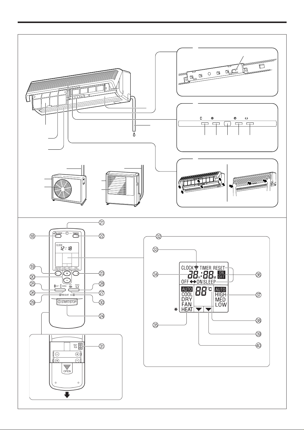
NAME OF PARTS
Instructions relating to heating (*) are applicable only to “HEAT & COOL MODEL” (Reverse Cycle).
Fig. 1
Fig. 5
E
F
D
A
B
G
E
F
G
0
C
Fig. 2
Fig. 3
Fig. 4
1
3
SWING SWINGTIMER
OPERATION
7
9
2
654 8
Fig. 6
Fig. 8
Fig. 7
En-3
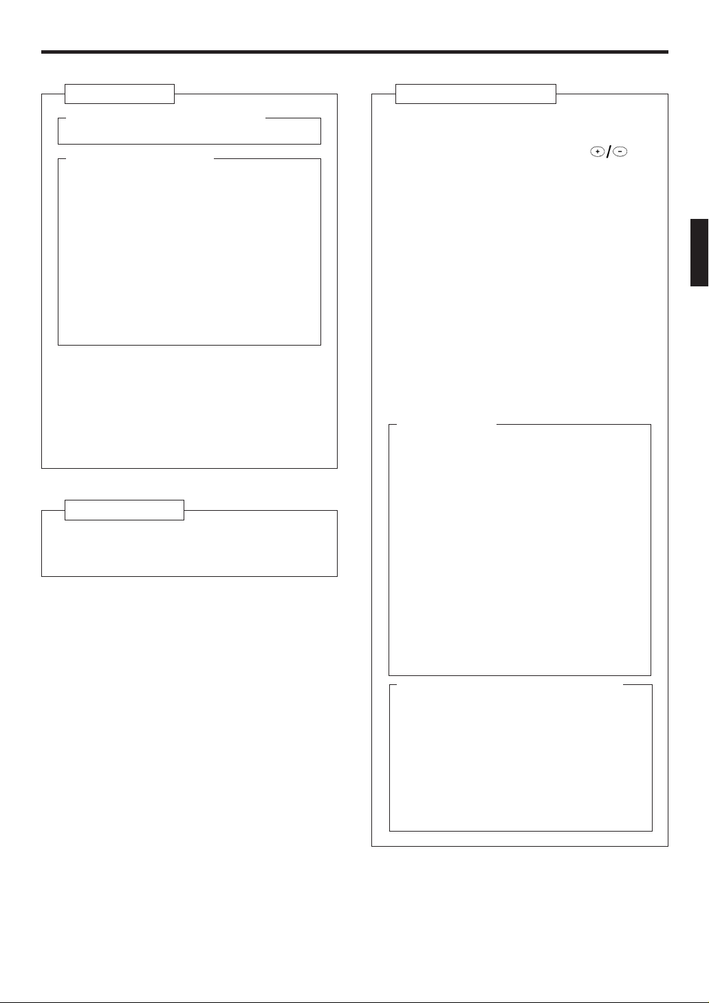
Fig. 1 Indoor Unit
1 Operating Control Panel (Fig. 2)
2 MANUAL AUTO button
3 Indicator Panel (Fig. 3)
4 Remote Control Signal Receiver
5 OPERATION Indicator Lamp (red)
6 TIMER Indicator Lamp (green)
7 SWING Indicator Lamp (orange)
(VERTICAL SWING)
8 SWING Indicator Lamp (orange)
(HORIZONTAL SWING)
If the TIMER indicator lamp flashes when
●
the timer is operating, it indicates that a
fault has occurred with the timer setting
(See page 16 Auto Restart).
9 Intake Grille (Fig. 4)
; UP/DOWN Air Direction Flaps
A Moving Diffuser
B RIGHT/LEFT Air Direction Louvers
(behind UP/DOWN Air Direction Flaps)
C Drain Hose
D Air Filter
Fig. 5 Outdoor Unit
E Intake Port
F Outlet Port
G Pipe Unit
Fig. 6 Remote Control Unit
H SLEEP button
I MASTER CONTROL button
J SET TEMP./SET TIME buttons (
K Signal Transmitter
L TIMER button
M FAN CONTROL button
N START/STOP button
O AIR FLOW DIRECTION
VERTICAL SET button
P AIR FLOW DIRECTION
VERTICAL SWING button
Q AIR FLOW DIRECTION
HORIZONTAL SET button
R AIR FLOW DIRECTION
HORIZONTAL SWING button
S TIME ADJUST button
T ACL button
(located inside battery compartment)
Rear side (Fig. 7)
U TEST RUN
● Touch the two metal contacts with a metallic object to send the signal to perform
a test run.
● Perform a test run only when installing the
air conditioner. If the signal to perform a
test run is received during normal operation, the air conditioner’s thermostat will
malfunction.
● If the signal to perform a test run is received during normal operation, the unit
will switch to the test operation mode and
the indoor unit’s OPERATION and TIMER
indicator lamps will flash simultaneously.
● To stop the test operation mode, press the
START/STOP button to stop the air conditioner.
V Remote Control Unit Display (Fig. 8)
W Transmit Indicator
X Clock Display
Y Operating Mode Display
Z T imer Mode Display
[ Fan Speed Display
\ Temperature Set Display
] T imer Set Indicator
` Temperature Set Indicator
)
En-4
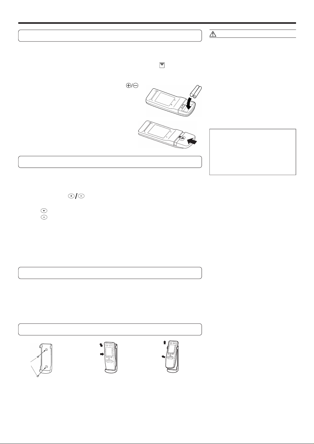
PREPARATION
Load Batteries (R03/LR03
××
× 2)
××
Press and slide the battery compartment lid on the re-
1
verse side to open it.
Slide in the direction of the arrow while pressing the mark.
Insert batteries.
2
Be sure to align the battery polarities ( ) correctly.
Close the battery compartment lid.
3
Set the Current time
Press the TIME ADJUST button.
1
Use the tip of a ball-point pen or other small object to press the button.
Use the ( ) SET TIME buttons to adjust the clock
2
to the current time.
button: Press to advance the time.
button: Press to reverse the time.
(Each time the buttons are pressed, the time will be advanced/reversed in
one-minute increments; hold the buttons depressed to change the time
quickly in ten-minute increments.)
CAUTION!
● Take care to prevent infants from
accidentally swallowing batteries.
● When not using the remote control unit
for an extended period, remove the
batteries to avoid possible leakage and
damage to the unit.
● If leaking battery fluid comes in contact
with your skin, eyes, or mouth, immediately wash with copious amounts of
water, and consult your physician.
● Dead batteries should be removed
quickly and disposed of properly, either
by placing in a public battery collection
receptacle, or by returning to appropriate authority.
● Do not attempt to recharge dry batteries.
Never mix new and used batteries, or
batteries of different types.
Batteries should last about one year
under normal use. If the remote control
unit’s operating range becomes appreciably reduced, replace the batteries and
press the ACL button with the tip of a
ballpoint pen or other small object.
Press the TIME ADJUST button again.
3
This completes the time setting and starts the clock.
To Use the Remote Control Unit
● The remote control unit must be pointed at signal receiver to operate correctly.
● Operating range: About 7 meters.
● When a signal is properly received by the air conditioner, a beeping sound will
be heard.
● If no beep is heard, press the remote control unit button again.
Remote Control Unit Holder
Insert
Press in
Screws
1 Mount the Holder. 2 Set the Remote Control Unit.
Slide up
Pull out
3 To remove the Remote
Control Unit (when use at
hand).
En-5
 Loading...