


AIR CONDITIONER
INDOOR UNIT
Duct type
INSTALLATION MANUAL
For authorized service personnel only.
Contents
1. SAFETY PRECAUTIONS 2
2. ABOUT THE UNIT 2
2.1.Precautions for using R410A refrigerant
2.2.Special tools for R410A
2.3.Accessories
2.4.Optional parts
3. INSTALLATION WORK 3
3.1.Selecting an installation location
3.2.Installation dimension
3.3.Installation the unit
4. PIPE INSTALLATION 6
4.1.Selecting the pipe material
4.2.Pipe requirement
4.3.Flare connection (pipe connection)
4.4.Installing heat insulation
5. INSTALLING DRAIN HOSE 8
6. ELECTRICAL WIRING 9
6.1.Electrical requirement
6.2.Wiring method
7. REMOTE CONTROLLER SETTING 11
7.1.Installing the remote controller
7.2.Setting the dip switches
8. FUNCTION SETTING 12
8.1.Tuning on the power
8.2.Function setting
8.3.Setting the room temperature detection location
9. STATIC PRESSURE CHARACTERISTIC 14
10. TEST RUN 14
11. CHECK LIST 14
12. ERROR CODES 15
13. SPECIAL INSTALLATION METHODS 15
13.1.Group control system
13.2.Dual remote controllers
14. FRESH-AIR INTAKE 16
15. CUSTOMER GUIDANCE 16
PART NO. 9379127004
1. SAFETY PRECAUTIONS
•Be sure to read this Manual thoroughly before installation.
•The warnings and precautions indicated in this Manual contain important information pertaining to your safety. Be sure to observe them.
•Hand this Manual, together with the Operating Manual, to the customer. Request the customer to keep them on hand for future use, such as for relocating or repairing the unit.
This mark indicates procedures which,
 WARNING if improperly performed, might lead to the death or serious injury of the user.
•Request your dealer or a professional installer to install the indoor unit in accordance with this Installation
Manual. An improperly installed unit can cause serious accidents such as water leakage, electric shock, or fire. If the indoor unit is installed in disregard of the instructions in the Installation Manual, it will void the manufacturer’s warranty.
•Do not turn ON the power until all work has been completed. Turning ON the power before the work is completed can cause serious accidents such as electric shock or fire.
•If refrigerant leaks while work is being carried out, ventilate the area. If the refrigerant comes in contact with a flame, it produces a toxic gas.
•Installation work must be performed in accordance with national wiring standards by authorized personnel only.
|
This mark indicates procedures which, |
|
CAUTION |
if improperly performed, might possibly |
|
result in personal harm to the user, or |
||
|
||
|
damage to property. |
2.ABOUT THE UNIT
2.1.Precautions for using R410A refrigerant
 WARNING
•Do not introduce any substance other than the prescribed refrigerant into the refrigeration cycle. If air enters the refrigeration cycle, the pressure in the refrigeration cycle will become abnormally high and cause the piping to rupture.
•If there is a refrigerant leak, make sure that it does not exceed the concentration limit. If a refrigerant leak
exceeds the concentration limit, it can lead to accidents such as oxygen starvation.
•Do not touch refrigerant that has leaked from the refrigerant pipe connections or other area. Touching the refrigerant directly can cause frostbite.
•If a refrigerant leak occurs during operation, immediately vacate the premises and thoroughly ventilate the area. If the refrigerant comes in contact with a flame, it produces a toxic gas.
2.2. Special tool for R410A
 WARNING
•To install a unit that uses R410A refrigerant, use dedicated tools and piping materials that have been manufactured specifically for R410A use. Because the pressure of R410A refrigerant is approximately 1.6 times higher than the R22, failure to use dedicated piping material or improper installation can cause rupture or injury.
Furthermore, it can cause serious accidents such as water leakage, electric shock, or fire.
Tool name |
Changes |
|
|
The pressure in the refrigerant |
|
|
system is extremely high and can- |
|
|
not be measured with a conven- |
|
|
tional gauge. To prevent erroneous |
|
|
mixing of other refrigerants, the |
|
Gauge manifold |
diameter of each port has been |
|
|
changed. It is recommended to use |
|
|
a gauge manifold with a high |
|
|
pressure display range of –0.1 to |
|
|
5.3 MPa and a low pressure dis- |
|
|
play range of –0.1 to 3.8 MPa. |
|
|
To increase pressure resistance, |
|
|
the hose material and base size |
|
Charging hose |
were changed. |
|
(The charging port thread diameter |
||
|
||
|
for R410A is 1/2 UNF 20 threads |
|
|
per inch.) |
|
|
A conventional vacuum pump can |
|
|
be used by installing a vacuum |
|
|
pump adapter. |
|
Vacuum pump |
Be sure that the pump oil does |
|
|
not backflow into the system. Use |
|
|
one capable for vacuum suction of |
|
|
–100.7 kPa (5 torr, –755 mmHg). |
|
Gas leakage detector |
Special gas leakage detector for |
|
R410A refrigerant . |
2.3. Accessories
 WARNING
•For installation purposes, be sure to use the parts supplied by the manufacturer or other prescribed parts.
The use of non-prescribed parts can cause serious accidents such as the unit to falling, water leakage, electric shock, or fire.
•The following installation parts are furnished. Use them as required.
•Keep the Installation Manual in a safe place and do not discard any other accessories until the installation work has been completed..
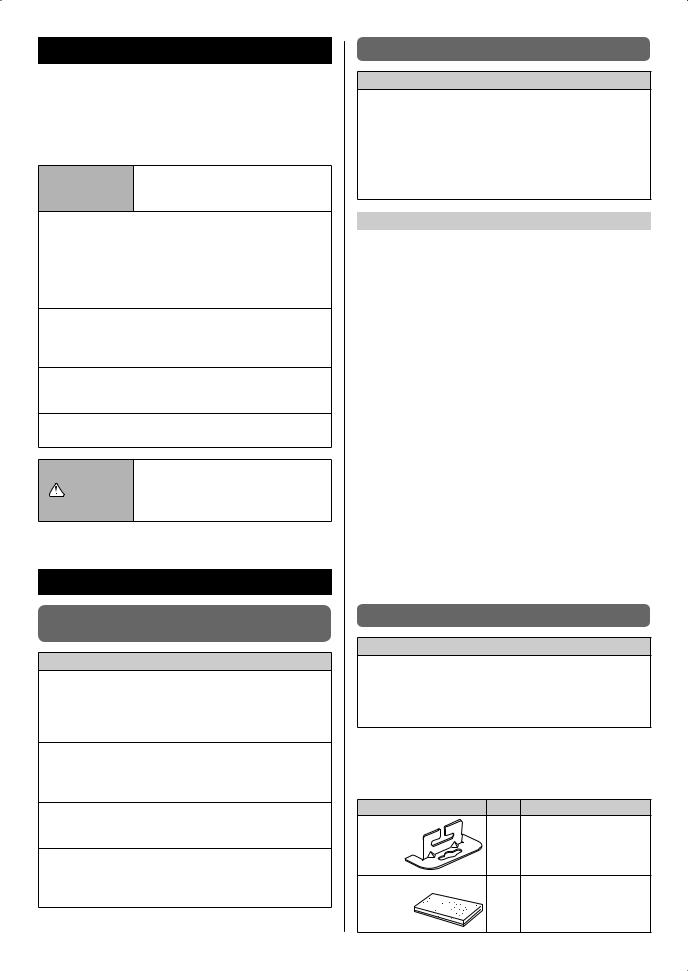
Name and Shape |
Q’ty |
Description |
Hanger |
|
For suspending the indoor |
|
4 |
unit from ceiling |
|
|
|
Drain hose insulation |
|
Insulates the drain hose |
|
1 |
and vinyl hose |
|
|
En-2

Binder (Large) |
1 |
For fixing the drain hose |
Binder (Small) |
|
For remote controller and |
|
1 |
remote controller cable |
|
|
binding |
Remote |
|
For air conditioner opera- |
controller |
1 |
tion |
|
|
|
Remote controller cable |
|
For connecting the remote |
(*1) |
1 |
controller |
|
|
|
Screw |
2 |
For installing the remote |
(M4 × 16) |
controller |
|
Coupler heat |
1 |
For indoor side pipe joint |
insulation (large) |
(gas) |
|
Coupler heat |
1 |
For indoor side pipe joint |
insulation (small) |
(liquid) |
|
Special nut A |
|
For suspending the indoor |
(large flange) |
4 |
unit from ceiling |
Special nut B |
|
For suspending the indoor |
(small flange) |
4 |
unit from ceiling |
(*1) Not supplied for ART series
2.4. Optional parts
|
Exterior |
Parts name |
Model No. |
Summary |
|
40 |
|
|
|
|
|
204 |
|
|
Square |
UTD-SF045T |
|
|
|
flange |
|
||
|
|
1065 |
|
|
|
|
|
|
|
|
|
|
|
Unit : mm |
|
|
|
|
|
|
Flexible |
UTD-RD202 |
|
|
|
ø200 mm |
duct |
|
|
|
|
|
|
||
|
|
L 2 m |
|
|
|
|
ø195 ø205 |
ø235 |
Round |
|
|
|
ø225 |
UTD-RF204 |
|
||
85 |
|
flange |
|
|
|
|
Unit : mm |
|
|
|
|
|
|
|
|
|
|
|
|
239 |
Long-life |
UTD-LF25NA |
|
|
|
|
filter |
|
|
|
507 |
|
|
|
|
|
|
|
|
|
|
|
|
Unit : mm |
|
|
|
|
|
|
|
|
New amen- |
|
|
|
|
|
ity space |
|
|
|
|
|
can be |
|
|
|
Remote |
|
offered by |
|
|
|
UTD-RS100 |
installing |
|
|
|
|
sensor |
||
|
|
|
|
the Remote |
|
|
|
|
|
|
|
|
|
|
|
|
sensor in |
|
|
|
|
|
the remote |
|
|
|
|
|
controller |
External
control UTD-ECS5A set
Drain
pump UTZ-PX1NBA unit
Receiver UTY-LRH** unit
3. INSTALLATION WORK
Especially, the installation place is very important for the split type air conditioner because it is very difficult to move from place to place after the first installation.
3.1. Selecting an installation location
Decide the mounting position together with the customer as follows.
 WARNING
•Select installation locations that can properly support the weight of the indoor unit. Install the units securely so that they do not topple or fall.
 CAUTION
•Do not install the indoor unit in the following areas:
•Area with high salt content, such as at the seaside. It will deteriorate metal parts, causing the parts to fall or the unit to leak water.
•Area filled with mineral oil or containing a large amount of splashed oil or steam, such as a kitchen. It will deteriorate plastic parts, causing the parts to fall or the unit to leak water.
•Area that generates substances that adversely affect the equipment, such as sulfuric gas, chlorine gas, acid, or alkali. It will cause the copper pipes and brazed joints to corrode, which can cause refrigerant leakage.
•Area that can cause combustible gas to leak, contains suspended carbon fibers or flammable dust, or volatile inflammables such as paint thinner or gasoline. If gas leaks and settles around the unit, it can cause a fire.
•Area where animals may urinate on the unit or ammonia may be generated.
•Do not install where there is the danger of combustible gas leakage.
•Do not install the unit near a source of heat, steam, or flammable gas.
•Install the indoor unit, outdoor unit, power supply cable, transmission cable, and remote control cable at least 1 m away from a television or radio receivers. The purpose of this is to prevent TV reception interference or radio noise. (Even if they are installed more than 1 m apart, you could still receive noise under some signal conditions.)
•If children under 10 years old may approach the unit, take preventive measures so that they cannot reach the unit.
•Take precautions to prevent the unit from falling.
En-3
(1) Install the indoor unit on a place having a sufficient strength so that it withstands against the weight of the indoor unit.
(2) The inlet and outlet ports should not be obstructed; the air should be able to blow all over the room.
(3) Leave the space required to service the air conditioner.
(4) Install the unit where connection to the outdoor unit is easy.
(5) Install the unit where the connection pipe can be easily installed.
(6) Install the unit where the drain pipe can be easily installed.
(7) Install the unit where noise and vibrations are not amplified.
(8) Take servicing, etc., into consideration and leave the spaces. Also install the unit where the filter can be removed.
(9) Providing as much space as possible between the indoor unit and the ceiling will make work much easier.
(10) If installing in a place where its humidity exceeds 80%, use heat insulation to prevent condensation.
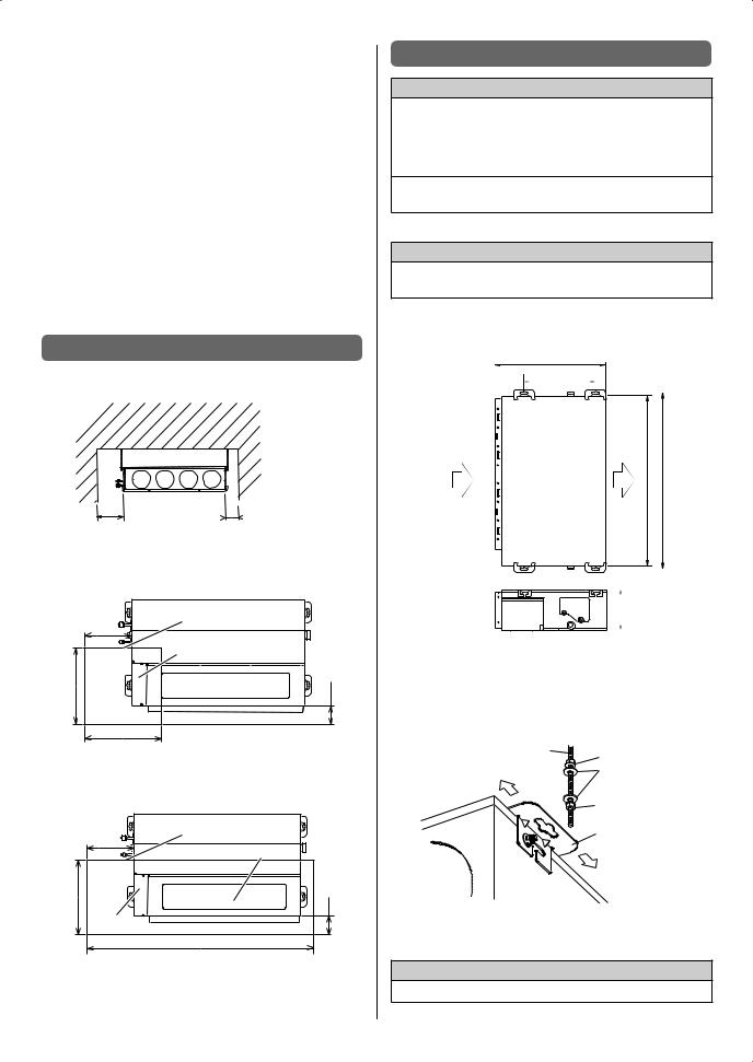
3.2. Installation dimension
Provide the space around the unit as shown in the following figure.
300 |
150 |
|
or more |
or more |
Unit : mm |
Maintenance hole dimension
It shall be possible to install and remove the control box.
|
300 |
Maintenance hole |
|
|
|
|
|
Control box |
500 |
|
100 |
|
500 |
Unit : mm |
|
|
It shall be possible to install and remove the control box, fan units and filter.
|
300 |
Maintenance hole |
|
Intake panel |
|
|
|
|
500 |
|
100 |
|
Control box |
|
|
|
1550 |
|
|
Unit : mm |
3.3. Installation the unit
 WARNING
•Install the air conditioner in a location which can withstand a load of at least five times the weight of the main unit and which will not amplify sound or vibration. If the installation location is not strong enough, the indoor unit may fall and cause injuries.
•If the job is done with the panel frame only, there is a risk that the unit will come loose. Please take care.
3.3.1. Installing the hangers
 WARNING
•When fastening the hangers, make the bolt positions uniform.
Hanging bolt installation diagram. (Example)
740
 477
477
(Top side)
AIR |
AIR 1135 1177 |
(Left side)
270
Unit : mm
The distance of  is adjustable according to the place of the hanging bolts.
(MAX : 550 mm, MIN : 410 mm)
Slide the unit in the arrow direction and fasten it.
Hanging bolt M10 |
Special nut A |
(Obtained locally) |
Washer (Obtained locally)
Special nut B
Hanger
Bolt Strength [N·m (kgf·cm)] |
9.81 to 14.71 (100 to 150) |
 CAUTION
• Fasten the unit securely with special nuts A and B.
En-4
3.3.2. Leveling
Base vertical direction leveling on the unit (right and left).
(Left side) |
Level meter |
AIR |
AIR |
Base horizontal direction leveling on top of the unit.
0-5 mm |
Drain hose |
Give a slight tilt to the side to which the drain hose is connected.
The tilt should be in the range of 0 mm to 5 mm.
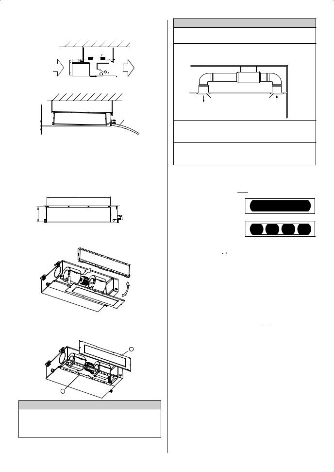
3.3.3. Intake duct connection
Follow the procedure in the following figure to the ducts.
1015
240
Unit : mm
The air inlet duct can be changed by replacing the intake grille and flange.
For the bottom air intake, follow the procedure of ○1 →○2 for installation.
(The factory setting is back air intake.)
2
1
 CAUTION
•When air is taken in from the bottom side, the operating sound of the product will easily enter the room. Install the product and intake grilles where the affect of the operating sound is small.
 CAUTION
•If an intake duct is installed, take care not to damage the temperature sensor.
•Be sure to install the air inlet grille and the air outlet grille for air circulation. The correct temperature cannot be detected.
|
Unit |
Air Outlet Grille |
Air Inlet Grille |
(Room) |
|
•Grills must be fixed so that man cannot touch indoor unit fan, and cannot be removed by only hand operation without tool.
•Be sure to install the air filter in the air inlet. If the air filter is not installed, the heat exchanger may be clogged and its performance may decrease.
3.3.4. Outlet duct connection
Duct installation pattern ( 
 CUT PART)
(1) Square duct
(2) Round duct outlet ×4 (This is the factory setting.)
When using as a square duct
(1) Cut the slit seam  with a cutter.
(2) Turn up the insulation around the points to be cut according to the outlet port shape working points so that the insulation does not stick out at the 

 part.
part.
Cut |
Cut |
Cut |
Cut |
(3) Cut with nippers and remove the sheet metal.
En-5
 Loading...