


ARHA24LU
R410A
INDOOR UNIT
1. DUCT
AR A24LATU
TYPE :
D2D_AR030E/04
2008.04.14
1. FEATURE
MODEL :
DUCT TYPE
AR A24L
INDOOR UNIT
OUTDOOR UNIT
AO A24LACL AO B24LACL
AR A24LATU
AO A24LALL AO B24LALL
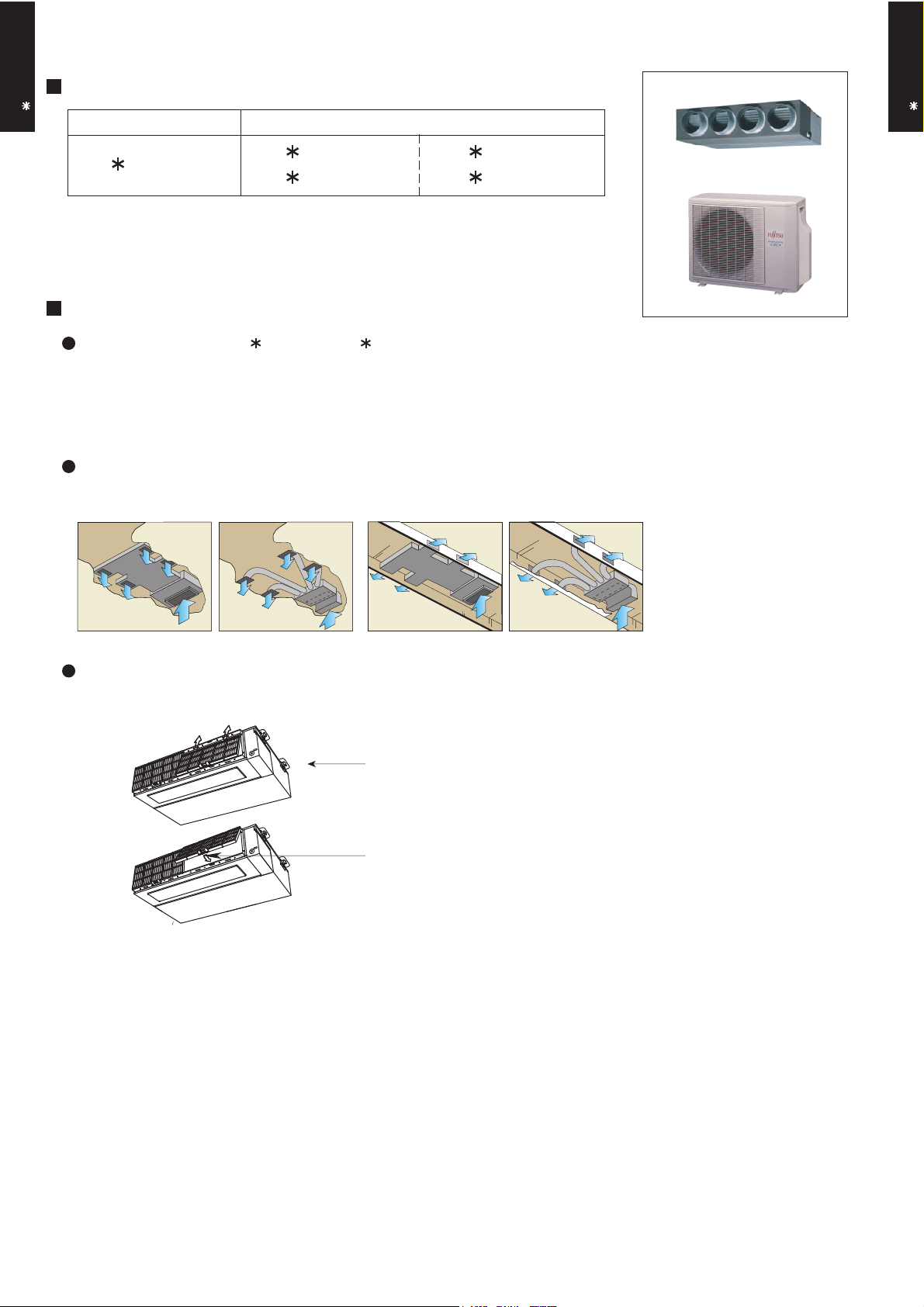
FEATURES
Energy saving (AO A24LACL, AO A24LALL connection model)
High energy saving was realized by making the indoor unit and outdoor
unit fan motor and compressor all DC and optimal design of the refrigerant cycle. Rank A was achieved in European energy rank.
Installation styles
Embedded in Ceiling
Hanging from Ceiling
DUCT TYPE
AR A24L
Slim & compact design
In the case of bottom suction type, as seen from lower rear part.
Control Box united with main unit
One-touch operating and easy-to-install
long-life filter (optional)
In addition to the slim height of 270 mm which is our sales point, further
com-pactification is attained by reducing 65 mm from the width with the
flanking control box embedded inside the chassis.
- (01 - 01) -
EASY MAINTENANCE
DUCT TYPE
AR A24L
In the case of rear suction type, as seen from lower rear part.
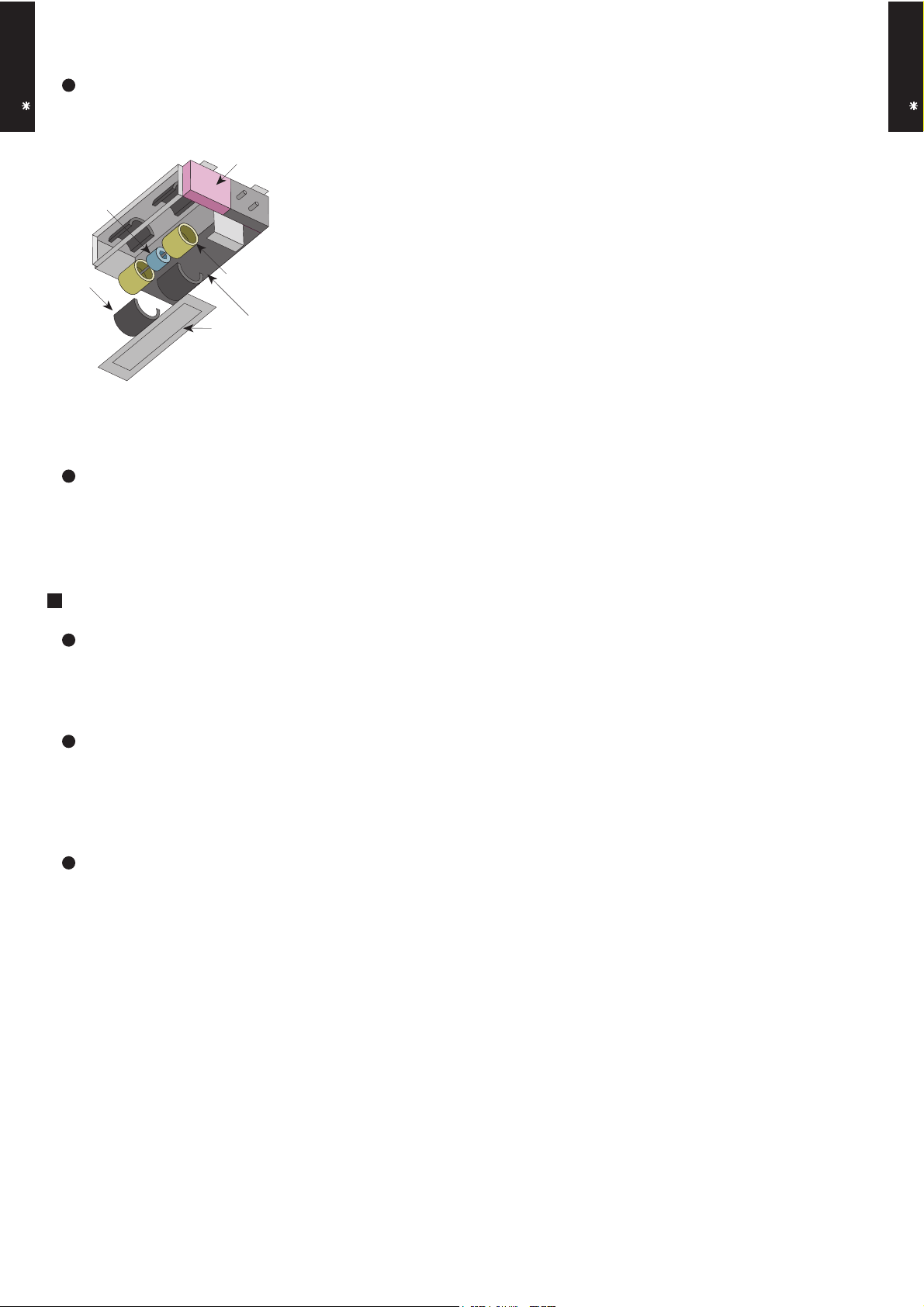
1
1. Control box
4
2. Fan casing
3. Fan
4. Motor
2
3
Bottom panel: 2 units
The motor and fan maintenance and dismounting can be made easily by removing
the rear panel and lower part of the casing with the main chassis installed.
Quiet mode
Operation at *25dB(A) possible by Quiet Mode.
* See our measurement conditions page (01-14).
DUCT TYPE
AR A24L
FUNCTION SETTING
Static pressure mode setting
Air flow, noise, etc. can be used under the optimum conditions by selecting
the static pressure mode matched to the installation conditions.
Room temperature adjustment correction
Suitable room temperature control is performed by changing the room temperature correction value by simple remote control operation to match the
conditions under which the air conditioner is installed.
Auto restart
The units restart automatically when the current was returned even when
there was a power interruption during operation.
- (01 - 02) -

2. REMOTE CONTROLLER
WIRED REMOTE CONTROLLER
DUCT TYPE
AR A24L
FEATURES
Various timer setup (ON / OFF / WEEKLY) are possible.
Equipped with weekly timer as standard function.
(2 times Start / Stop per day for a week)
When setting up a timer, operation mode and a temperature
setup can be changed.
When a failure occurs,the error code is displayed. (Maximum of 16)
Error indication.(A maximum of 16 error histories are memorizable.)
Up to 16 indoor units can be simultaneously controlled.
Economy operation are possible.
Easy installation with a slim shape with no bulge in the back.
The room temperature can be controlled by being detected the temperature
accurately with built-in thermo sensor.
Simple function setting
Setting of the air conditioner selection function is performed by remote controller.
DUCT TYPE
AR A24L
High performance and compact size
Three functions are combined in
one unit.
Wired
remote
controller
Built-in timers
Possible to set ON/OFF time to operate twice each day
of the week.
SUMOTUWETH FR SA
7
3126 9
15 18 21
Setup screen example
(Set to Wednesday: 8:00 to 20:00.)
0 3 6 9 12 15 18 21 Time
At "Weekly timer" + "Set back timer" setup
Easy-to-understand time bar display
SUMOTUWETH FR SA
7
3126 9
15 18 21
24°C
24°C 28°C 24°C
Screen
after setup
Weekly
timer
Setback
timer
Setback timerWeekly timer
Possible to set temperature for two time spans and
for each day of the week.
SUMOTUWETH FR SA
3126 9
15 18 21
Setup screen example
(Set from Sunday to Saturday: 12:00 to 15:00, 28 °C.)
0 3 6 9 12 15 18 21 Time
24°C
0 3 6 9 12 15 18 21 Time
28°C
28°C
Easy-to-understand operation Simple installation
Components are compatible with standard
switch boxes. Flat back construction allows
equipment to be installed wherever it is
Timer
area
[
Variable timer control
]
Operation
area
The operation/display sections are zoned according to time and operation, enabling variable programming to match application.
- (01 - 03) -
needed.
European
switch box
JIS box

DUCT TYPE
AR A24L
FUNCTIONS
2
6
7
8
9
10
11
Display panel
16
19
20
18
17
15
13
12
14
DUCT TYPE
1
START/STOP button
Pressed to start and stop operation.
2
Set temperature button
Selects the setting temperature.
3
Master control button
Selects the operating mode(AUTO, HEAT, FAN, COOL, DRY).
4
1
3
4
5
Fan control button
Selects the fan speed (AUTO, QUIET, LOW, MED, HIGH).
5
Economy button
Turns the economy efficient mode on and off.
6
Timer mode (CLOCK ADJUST) button
Selects the timer mode (OFF TIMER, ON TIMER, WEEKLY TIMER).
Set the current time.
7
Day (DAY OFF) button
Temporarily cancels of one day timer.
8
Set back button
Pressed to select the set back timer.
9
Set time button
Pressed to set time.
10
Delete button
The schedule of a weekly timer is deleted.
11
Set button
Sets the date, hour, minute and on-off time.
12
Vertical airflow direction and swing button*
Push for two seconds to change the swing mode.
13
Horizontal airflow direction and swing button*
Push for two seconds to change the swing mode.
AR A24L
DIMENSION
120
Front View
SPECIFICATION
21
[ Unit : mm ]
120
14
Filter button*
15
Operation lamp
Lights during operation and when the timer is on.
16
Timer and clock display
17
17
Operation mode display
18
Fan speed display
19
Operation lock display
20
Temperature display
21
Function display
Defrost display
Thermo sensor display
Economy display
Vertical swing display*
Horizontal swing display*
Filter display*
SIZE (H x W x D mm) 120 x 120 x 17
WEIGHT ( g ) 160
CABLE LENGTH ( m )
POWER ( V )
10
12
*These functions are not available.
- (01 - 04) -

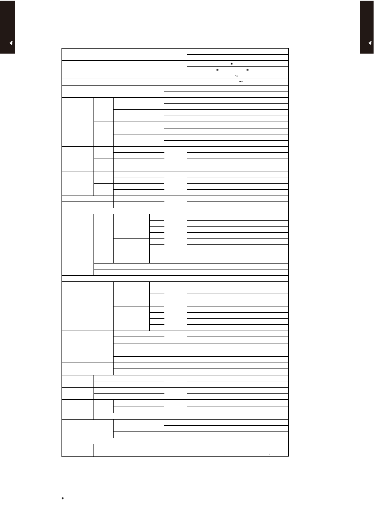
3. SPECIFICATIONS
DUCT TYPE
AR A24L
Type
Model name
Power source
Available voltage range
European energy label
Cooling
Capacity
Heating
Input power
Current
EER 3.21
COP 3.61
Moisture removal
Fan
Recommended static pressure Pa 30 to 150
Sound pressure level
Heat exchanger type
Enclosure
Dimensions
( H×W ×D )
Weight
Connection pipe
Operation range
Remote controller type
Drain pipe
Cooling
Heating
Cooling
Heating
Airflow
rate
Type × Q'ty Sirocco × 2
Motor output W 115
Net 270 × 1135 × 700
Gross 300 × 1300 × 790
Net 38 ( 84 )
Gross 45 ( 99 )
Size mm
Method Flare
Material
Size
Rated
Min.-Max.
Rated
Min.-Max.
Rated
*Max.
Rated
*Max.
Rated
*Max.
Rated
*Max.
Cooling
Heating
Cooling
Heating
Cooling
Heating
Dimensions (H × W × D) 294 × 1000 × 39.9
Fin pitch 1.40
Rows x Stages 3 × 14
Pipe type Copper
Fin type Aluminium
Material Steel
Colour
Liquid 6.35 ( 1 / 4 in.)
Gas 15.88 ( 5 / 8 in.)
Cooling
Heating °C 30 or less
Cooling A
Heating A
kW 7.10
BTU/h 24200
kW 0.90 - 8.00
BTU/h 3100 - 27300
kW 8.00
BTU/h 27300
kW 0.90 - 9.10
BTU/h 3100 - 31000
kW
A
kW/kW
l/h (pints/h) 2.5 (4.4)
High 1100
Med 950
Low 800
Quiet 600
Quiet 600
Quiet 25
Quiet 25
m3/h
High 1100
Med 950
Low 800
High 31
Med 29
Low 27
dB(A)
High 31
Med 29
Low 27
mm
mm
kg(lb.)
°C 18 to 32
%RH 80 or less
mm Outer diameter : 38.0 / Inner diameter : 36.0
DUCTED MODEL
INVERTER HEATPUMP
AR A24LATU
AO A24LACL, AO A24LALL
230V 50Hz
198-264V 50Hz
2.21
2.85
2.21
3.19
9.7
12.0
9.7
13.5
Wired
Steel
DUCT TYPE
AR A24L
Note :
Specifications are ased on the following conditions.
Cooling : Indoor temperature of 27 °CDB / 19 °CWB.and outdoor temperature of 35 °CDB/24°CWB.
Heating : Indoor temperature of 20 °CDB / 15 °CWB.and outdoor temperature of 7 °CDB/6 °CWB.
Standard static pressure : 30 Pa
Pipe length : 7.5 m, Height difference : 0 m.(Outdoor unit - Indoor unit)
Sound pressure level : Install a 2m duct to the outlet port and a 1m duct to the suction poit and measure.
*
The maximum current and the maximum input value are the maximum values when operated within the operation range (temperature).
- (01 - 05) -
DUCTED MODEL
INVERTER HEATPUMP
AR A24LATU
AO B24LACL, AO B24LALL
230V 50Hz
198-264V 50Hz
Cooling B
Heating B
kW 7.10
BTU/h 24200
kW 0.90 - 7.80
BTU/h 3100 - 26600
kW 8.00
BTU/h 27300
kW 0.90 - 8.80
BTU/h 3100 - 30000
2.32
2.85
2.33
3.19
10.1
12.0
10.2
13.5
EER 3.06
COP 3.43
l/h (pints/h) 2.5 (4.4)
High 1100
Med 950
Low 800
Quiet 600
High 1100
Med 950
Low 800
Quiet 600
Type × Q'ty Sirocco × 2
Motor output W 115
Recommended static pressure Pa 30 to 150
High 31
Med 29
Low 27
Quiet 25
High 31
Med 29
Low 27
Quiet 25
Dimensions (H × W × D) 294 × 1000 × 39.9
Fin ptich 1.40
Rows x Stages 3 × 14
Pipe type Copper
Fin type Aluminium
Material Steel
Colour
Net 270 × 1135 × 700
Gross 300 × 1300 × 790
Net 38 ( 84 )
Gross 45 ( 99 )
Liquid φ 6.35 (φ 1 / 4 in.)
Gas φ15.88 (φ 5 / 8 in.)
Method Flare
°C 18 to 32
%RH 80 or less
Heating °C 30 or less
Wired
Steel
mm Outer diameter 38.0 / Inner diameter 36.0
Operation range
Cooling
Remote controller type
Drain pipe
Material
Size
Weight kg(lb.)
Connection pipe
Size mm
Heat exchanger type
mm
Enclosure
Dimensions
( H×W ×D )
mm
Sound pressure level
Cooling
dB(A)
Heating
Fan
Airflow
rate
Cooling
m3/h
Heating
Cooling
kW/kW
Heating
Moisture removal
Current
Cooling
Rated
A
*Max.
Heating
Rated
*Max.
Input power
Cooling
Rated
kW
*Max.
Heating
Rated
*Max.
Capacity
Cooling
Rated
Min.-Max.
Heating
Rated
Min.-Max.
Type
Power source
Available voltage range
European energy label
Model name
Note :
Specifications are based on the following conditions.
Cooling : Indoor temperature of 27 °CDB / 19 °CWB.and outdoor temperature of 35 °CDB/24°CWB.
Heating : Indoor temperature of 20 °CDB / 15 °CWB.and outdoor temperature of 7 °CDB/6 °CWB.
Standard static pressure : 30 Pa
Pipe length : 7.5 m, Height difference : 0 m.(Outdoor unit - Indoor unit)
Sound pressure level : Install a 2m duct to the outlet port and a 1m duct to the suction poit and measure.
The maximum current and the maximum input value are the maximum values when operated within the operation range (temperature).
- (01 - 06) -
DUCT TYPE
AR A24L
DUCT TYPE
AR A24L
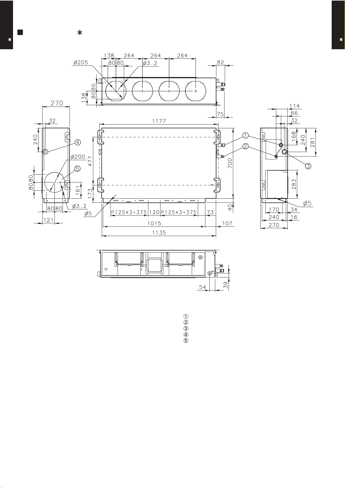
4. DIMENSIONS
MODEL : AR A24L
DUCT TYPE
AR A24L
Front view
(Unit : mm)
DUCT TYPE
AR A24L
Side view (L)
Top view
Rear view
Side view (R)
Refrigerant piping flare connection (Gas)
Refrigerant piping flare connection (Liquid)
Drain piping connection
Drain piping connection with cap.
Knock out hole for fresh air.
- (01 - 07) -
DUCT TYPE
AR A24L
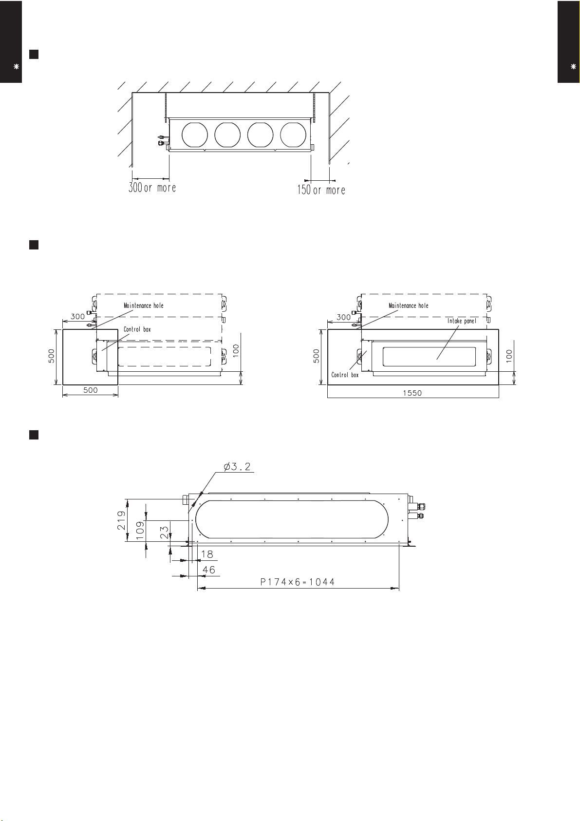
MOUNTING POSITION
MAINTENANCE HOLE
(Unit : mm)
DUCT TYPE
AR A24L
It shall be possible to install and remove
the control box.
WHEN USING A SQUARE DUCT
It shall be possible to install and remove
the control box, fan units and filter.
- (01 - 08) -

5. WIRING DIAGRAMS
MODEL : AR A24L
DUCT TYPE
AR A24L
DUCT TYPE
AR A24L
COIL
- (01 - 09) -
6. CAPACITY TABLE
-10
0
5
10
15
20
46
25
30
Outdoor temperature
°CDB
35
40
192123
AFR
18.3
Indoor temperature
18212325272932
121516
18
252032
2319211618
272923
°CDB
-10
0
5
10
15
AFR
18.3
Indoor temperature
18
21
Outdoor temperature
12
15
46
25
30
35
40
6-1. COOLING CAPACITY
DUCT TYPE
AR A24L
This table is created using the maximum capacity.
MODEL : AR A24L / AO A24L
°CDB
°CWB
TC SHC PI TC SHC PI TC SHC PI TC SHC PI TC SHC PI TC SHC PI TC SHC PI
5.62 4.62 0.60 6.26 4.65 0.61 6.47 5.05 0.62 6.90 5.07 0.62 7.11 5.48 0.62 7.54 5.45 0.63 7.97 5.81 0.64
5.53 4.58 0.65 6.16 4.60 0.66 6.37 5.00 0.66 6.79 5.02 0.67 7.00 5.42 0.67 7.42 5.40 0.68 7.83 5.75 0.68
5.34 4.49 0.79 5.94 4.51 0.80 6.15 4.91 0.80 6.55 4.92 0.81 6.75 5.32 0.82 7.16 5.29 0.82 7.57 5.64 0.83
5.13 4.38 0.92 5.71 4.40 0.93 5.90 4.79 0.94 6.29 4.80 0.95 6.49 5.19 0.95 6.88 5.17 0.96 7.27 5.50 0.97
5.25 4.44 0.76 5.85 4.47 0.78 6.05 4.86 0.78 6.45 4.87 0.79 6.65 5.26 0.79 7.05 5.24 0.80 7.45 5.58 0.81
6.78 5.21 1.61 7.55 5.24 1.64 7.81 5.70 1.65 8.32 5.72 1.66 8.58 6.18 1.67 9.09 6.15 1.69 9.61 6.55 1.70
6.45 5.04 1.81 7.18 5.07 1.84 7.43 5.51 1.85 7.92 5.53 1.87 8.16 5.97 1.88 8.65 5.95 1.90 9.14 6.34 1.91
6.10 4.87 2.01 6.80 4.90 2.04 7.03 5.32 2.05 7.50 5.34 2.07 7.73 5.77 2.08 8.19 5.74 2.10 8.65 6.12 2.12
6.32 4.98 2.53 7.04 5.01 2.57 7.28 5.45 2.58 7.76 5.46 2.61 8.00 5.90 2.62 8.48 5.88 2.65 8.96 6.26 2.67
5.13 4.38 2.05 5.71 4.41 2.08 5.91 4.79 2.09 6.30 4.80 2.11 6.49 5.19 2.12 6.88 5.17 2.14 7.27 5.51 2.16
3.66 3.68 1.56 4.08 3.70 1.58 4.22 4.02 1.59 4.50 4.03 1.60 4.64 4.36 1.61 4.91 4.34 1.63 5.19 4.62 1.64
DUCT TYPE
AR A24L
MODEL : AR A24L / AO B24L
°CDB
°CWB
TC SHC PI TC SHC PI TC SHC PI TC SHC PI TC SHC PI TC SHC PI TC SHC PI
5.62 4.62 0.60 6.26 4.65 0.61 6.47 5.05 0.62 6.90 5.07 0.62 7.11 5.48 0.62 7.54 5.45 0.63 7.97 5.81 0.64
5.53 4.58 0.65 6.16 4.60 0.66 6.37 5.00 0.66 6.79 5.02 0.67 7.00 5.42 0.67 7.42 5.40 0.68 7.83 5.75 0.68
5.34 4.49 0.79 5.94 4.51 0.80 6.15 4.91 0.80 6.55 4.92 0.81 6.75 5.32 0.82 7.16 5.29 0.82 7.57 5.64 0.83
5.13 4.38 0.92 5.71 4.40 0.93 5.90 4.79 0.94 6.29 4.80 0.95 6.49 5.19 0.95 6.88 5.17 0.96 7.27 5.50 0.97
5.25 4.44 0.76 5.85 4.47 0.78 6.05 4.86 0.78 6.45 4.87 0.79 6.65 5.26 0.79 7.05 5.24 0.80 7.45 5.58 0.81
6.78 5.21 1.61 7.55 5.24 1.64 7.81 5.70 1.65 8.32 5.72 1.66 8.58 6.18 1.67 9.09 6.15 1.69 9.61 6.55 1.70
6.45 5.04 1.81 7.18 5.07 1.84 7.43 5.51 1.85 7.92 5.53 1.87 8.16 5.97 1.88 8.65 5.95 1.90 9.14 6.34 1.91
6.10 4.87 2.01 6.80 4.90 2.04 7.03 5.32 2.05 7.50 5.34 2.07 7.73 5.77 2.08 8.19 5.74 2.10 8.65 6.12 2.12
6.16 4.81 2.53 6.86 4.84 2.57 7.10 5.26 2.58 7.57 5.28 2.61 7.80 5.70 2.62 8.27 5.68 2.65 8.74 6.05 2.67
5.00 4.24 2.05 5.57 4.27 2.08 5.76 4.64 2.09 6.14 4.65 2.11 6.33 5.03 2.12 6.71 5.01 2.14 7.09 5.33 2.16
3.57 3.58 1.56 3.98 3.60 1.58 4.11 3.91 1.59 4.38 3.93 1.60 4.52 4.24 1.61 4.79 4.22 1.63 5.06 4.50 1.64
AFR: Air Flow Rate (m3/min)
TC : Total Capacity (kW)
SHC: Sensible Heat Capacity (kW)
PI : Power Input (kW)
- (01 - 10) -
6-2. HEATING CAPACITY
20
15
24
18
10
8
15
10
5
3
7
6
-5
-7
0
-2
Outdoor temperature
°CDB
°CWB
-15
-16
-10
-11
AFR
18.3
Indoor temperature
°CDB16182022
24
-10
Indoor temperature
-5
161820
22
°CDB
°CWB
-15
24
0
-2
151820
7
3
10
15
10
6
AFR
°CDB
18.3
24
-16
-11
-7
Outdoor temperature
8
5
DUCT TYPE
AR A24L
This table is created using the maximum capacity.
MODEL : AR A24L / AO A24L
TC PI TC PI TC PI TC PI TC PI
6.27 2.75 6.12 2.81 5.97 2.87 5.82 2.93 5.67 2.98
7.10 2.97 6.93 3.04 6.76 3.10 6.60 3.16 6.43 3.22
7.94 3.12 7.75 3.18 7.56 3.25 7.37 3.31 7.18 3.38
8.80 3.05 8.59 3.12 8.38 3.18 8.17 3.25 7.96 3.31
9.72 3.08 9.49 3.14 9.26 3.21 9.03 3.27 8.80 3.34
9.56 2.66 9.33 2.71 9.10 2.77 8.87 2.83 8.65 2.88
9.85 2.66 9.62 2.72 9.38 2.78 9.15 2.83 8.91 2.89
9.03 2.13 8.82 2.17 8.60 2.22 8.39 2.26 8.17 2.31
8.29 1.65 8.09 1.69 7.90 1.72 7.70 1.76 7.50 1.79
8.58 1.65 8.38 1.68 8.17 1.72 7.97 1.75 7.77 1.79
DUCT TYPE
AR A24L
MODEL : AR A24L / AO B24L
TC PI TC PI TC PI TC PI TC PI
6.27 2.75 6.12 2.81 5.97 2.87 5.82 2.93 5.67 2.98
7.10 2.97 6.93 3.04 6.76 3.10 6.60 3.16 6.43 3.22
7.94 3.12 7.75 3.18 7.56 3.25 7.37 3.31 7.18 3.38
8.51 3.05 8.31 3.12 8.10 3.18 7.90 3.25 7.70 3.31
9.40 3.08 9.18 3.14 8.95 3.21 8.73 3.27 8.51 3.34
9.24 2.66 9.02 2.71 8.80 2.77 8.58 2.83 8.36 2.88
9.53 2.66 9.30 2.72 9.07 2.78 8.85 2.83 8.62 2.89
8.73 2.13 8.53 2.17 8.32 2.22 8.11 2.26 7.90 2.31
8.02 1.65 7.83 1.69 7.64 1.72 7.44 1.76 7.25 1.79
8.30 1.65 8.10 1.68 7.90 1.72 7.71 1.75 7.51 1.79
AFR: Air Flow Rate (m3/ min)
TC : Total Capacity (kW)
PI : Power Input (kW)
- (01 - 11) -
7. FAN PERFORMANCE AND CAPACITY
Hi
Med
Low
Quiet
m3/h
- - - - - 1200 1100 1000
m3/h
- - - 980 915 830 - -
m3/h
- - 825 690 - - - -
m3/h
630 525 - - - - - -
Static pressure (Pa)
FAN SPEED
Hi
Med
Quiet
Low
7-1. NORMAL MODE
DUCT TYPE
AR A24L
MODEL : AR A24L
6 11 14 21 25 30 35 40
l/s - - - - - 333 306 278
CFM - - - - - 706 647 589
l/s - - - 272 254 231 - -
CFM - - - 577 539 489 - -
l/s - - 229 192 - - - -
CFM - - 486 406 - - - -
l/s 175 146 - - - - - -
CFM 371 309 - - - - - -
Q-h Characteristic curve
50
40
DUCT TYPE
AR A24L
30
20
10
0
500 600 700 800 900 1,000 1,100 1,200 1,300
AIR FLOW (m3/h)
102.0 15.0
100.0
98.0
96.0
94.0
Cooling capacity(%) STATIC PRESSURE(Pa)Heating capacity(%)
92.0
500 600 700 800 900 1,000 1,100 1,200 1,300
Air temp
Capacity
COOLING
AIR FLOW (m3/h)
HEATING
102.0 50.0
100.0
98.0
96.0
94.0
92.0
500 600 700 800 900 1,000 1,100 1,200 1,300
Air temp
Capacity
AIR FLOW (m3/h)
- (01 - 12) -
14.5
14.0
13.5
13.0
12.5
12.0
11.5
11.0
10.5
10.0
49.0
48.0
47.0
46.0
45.0
44.0
43.0
42.0
41.0
40.0
Air temperature(°C)Air temperature(°C)
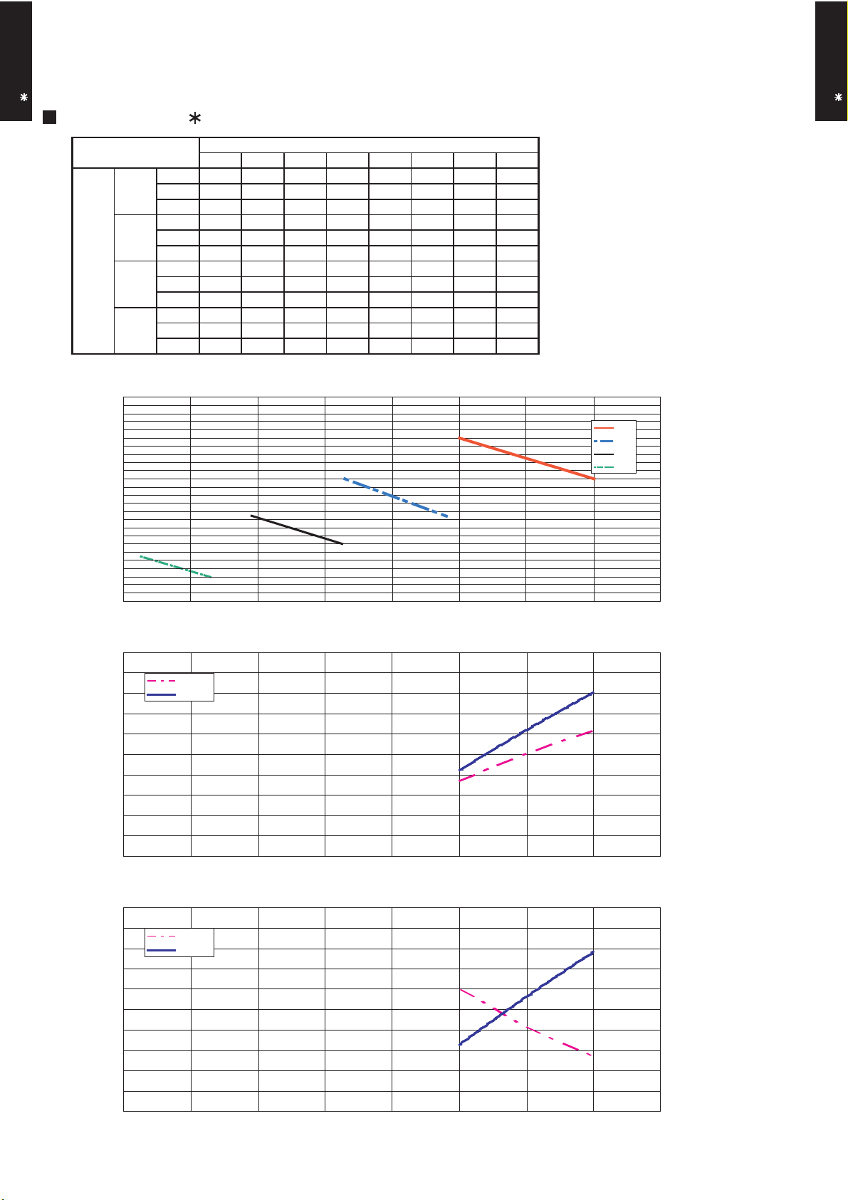
7-2. HIGH STATIC MODE
Hi
Med
Low
Quiet
m3/h
- - - - - - 1200 1000
m3/h
- - - - 1000 815 - -
m3/h
- - 830 680 - - - -
m3/h
650 540 - - - - - -
Static pressure (Pa)
Quiet
Med
Hi
FAN SPEED
Low
7-2-1. MODE 1
DUCT TYPE
AR A24L
MODEL : AR A24L
20 23 30 35 40 47 55 65
l/s - - - - - - 333 278
CFM - - - - - - 706 589
l/s - - - - 278 226 - -
CFM - - - - 589 480 - -
l/s - - 231 189 - - - -
CFM - - 489 400 - - - -
l/s 181 150 - - - - - -
CFM 383 318 - - - - - -
70
60
Q-h Characteristic curve
DUCT TYPE
AR A24L
50
40
30
20
10
500 600 700 800 900 1,000 1,100 1,200 1,300
AIR FLOW (m3/h)
102.0 15.0
100.0
98.0
96.0
94.0
Cooling capacity(%) STATIC PRESSURE(Pa)Heating capacity(%)
92.0
500 600 700 800 900 1,000 1,100 1,200 1,300
Air temp
Capacity
COOLING
AIR FLOW (m3/h)
HEATING
102.0 50.0
100.0
98.0
96.0
94.0
92.0
500 600 700 800 900 1,000 1,100 1,200 1,300
Air temp
Capacity
AIR FLOW (m3/h)
- (01 - 13) -
14.5
14.0
13.5
13.0
12.5
12.0
11.5
11.0
10.5
10.0
49.0
48.0
47.0
46.0
45.0
44.0
43.0
42.0
41.0
40.0
Air temperature(°C)Air temperature(°C)

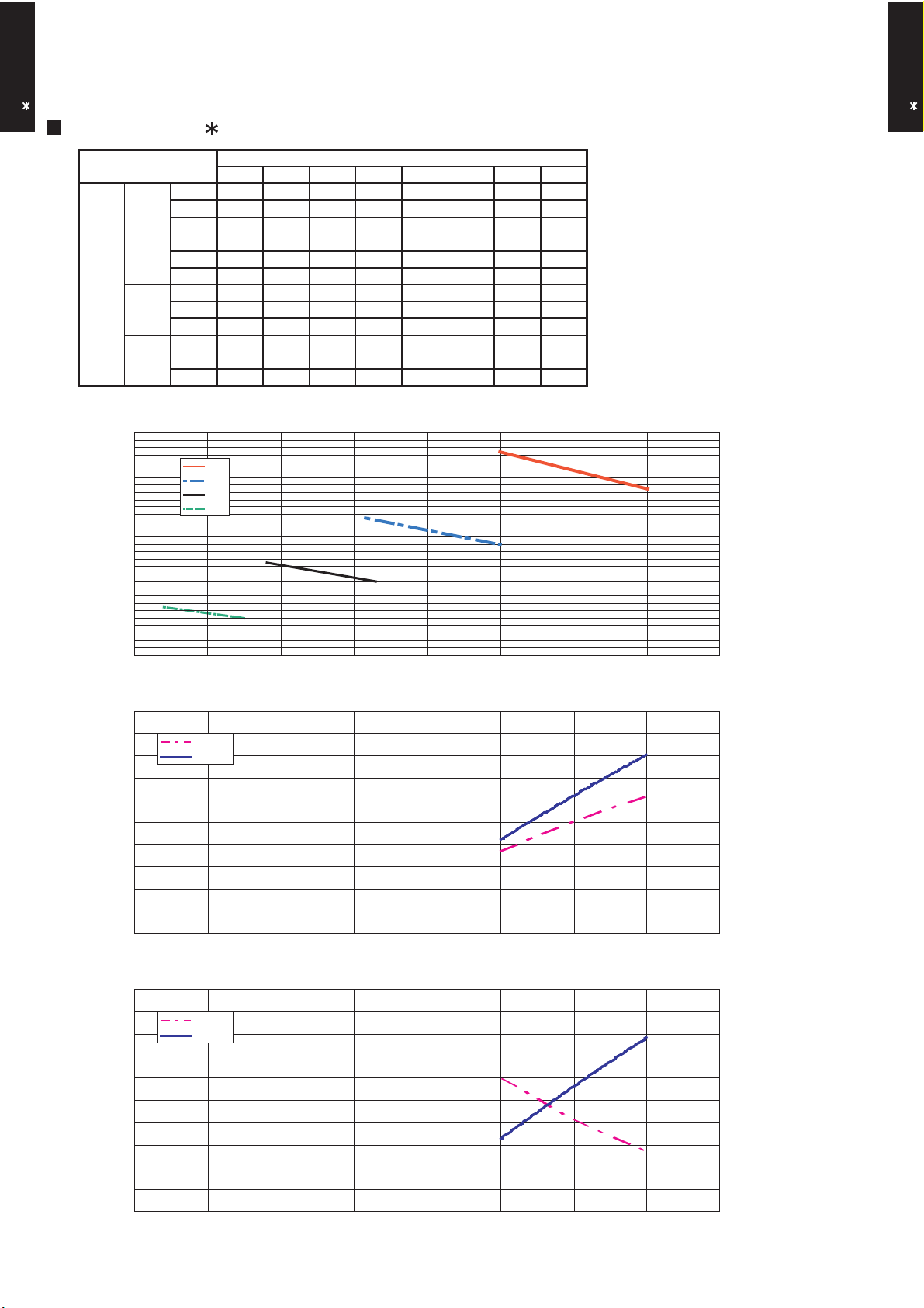
7-2-2. MODE 2
Hi
Med
Low
Quiet
m3/h
- - - - - - 1160 930
m3/h
- - - - 1020 800 - -
m3/h
- - 835 670 - - - -
m3/h
660 530 - - - - - -
Low
Static pressure (Pa)
FAN SPEED
Hi
Med
Quiet
DUCT TYPE
AR A24L
MODEL : AR A24L
110
100
90
80
70
35 37 50 55 68 75 93 100
l/s - - - - - - 322 258
CFM - - - - - - 683 547
l/s - - - - 283 222 - -
CFM - - - - 600 471 - -
l/s - - 232 186 - - - -
CFM - - 491 394 - - - -
l/s 183 147 - - - - - -
CFM 388 312 - - - - - -
Q-h Characteristic curve
DUCT TYPE
AR A24L
60
50
40
30
500 600 700 800 900 1,000 1,100 1,200 1,300
AIR FLOW (m3/h)
102.0 15.0
100.0
98.0
96.0
94.0
Cooling capacity(%) STATIC PRESSURE(Pa)Heating capacity(%)
92.0
500 600 700 800 900 1,000 1,100 1,200 1,300
Air temp
Capacity
COOLING
AIR FLOW (m3/h)
HEATING
102.0 50.0
100.0
98.0
96.0
94.0
92.0
500 600 700 800 900 1,000 1,100 1,200 1,300
Air temp
Capacity
AIR FLOW (m3/h)
- (01 - 14) -
14.5
14.0
13.5
13.0
12.5
12.0
11.5
11.0
10.5
10.0
49.0
48.0
47.0
46.0
45.0
44.0
43.0
42.0
41.0
40.0
Air temperature(°C)Air temperature(°C)
 Loading...