


GE Consumer & Industrial
Electrical Distribution
AF-650 GPTM & AF-600 FPTM
OPCMBTCP Modbus TCP Option

Modbus TCP
Contents
1 Safety |
3 |
Safety Note |
3 |
Safety Regulations |
3 |
Warning against Unintended Start |
4 |
2 Introduction |
5 |
Introduction |
5 |
About this Manual |
5 |
Assumptions |
5 |
Background Knowledge |
5 |
Modbus Conformance |
6 |
Abbreviations |
6 |
3 How to Install |
7 |
The Modbus TCP Option |
7 |
How to Install Option in Frequency Converter |
8 |
LED Behaviour |
9 |
Topology |
10 |
Network |
11 |
Recommended Design Rules |
12 |
EMC Precautions |
13 |
4 How to Configure |
15 |
IP Settings |
15 |
Ethernet Link Parameters |
16 |
Configuring the Scanner |
17 |
IP traffic |
21 |
5 How to Control |
23 |
How to Control the Frequency Converter |
23 |
Function Codes Supported by Modbus TCP |
23 |
Modbus TCP Message Framing Structure |
23 |
Function Code |
23 |
Data Field |
23 |
CRC Check Field |
23 |
Holding Register Addressing |
24 |
Examples |
26 |
Control Profile |
27 |
GE Drive Control Profile |
28 |
Status Word according to Drive Profile (STW) |
30 |
Reference Handling |
31 |
1

Modbus TCP
Bus Speed Reference Value |
31 |
6 Parameters |
33 |
Parameter Group O-## |
33 |
Parameter Group EN-## |
37 |
Modbus TCP |
40 |
Parameter List |
44 |
Data Types |
46 |
Data Types Supported by AF-650 GP/AF-600 FP |
46 |
7 Troubleshooting |
47 |
Troubleshooting |
47 |
Step-by-step Troubleshooting |
47 |
Alarm Word and Warning Word |
48 |
Index |
51 |
2

Modbus TCP
1 Safety
1
1.1.1 Copyright, Limitation of Liability and Revision Rights
This publication contains information proprietary to GE. By accepting and using this manual the user agrees that the information contained herein will be used solely for operating equipment from GE or equipment from other vendors provided that such equipment is intended for communication with GE equipment over an Ethernet serial communication link. This publication is protected under the Copyright laws of Denmark and most other countries.
GE does not guarantee that a software program produced according to the guidelines provided in this manual will function properly in every physical, hardware or software environment.
Although GE has tested and reviewed the documentation within this manual, GE makes no warranty or representation, either express or implied, with respect to this documentation, including its quality, performance, or fitness for a particular purpose.
In no event shall GE be liable for direct, indirect, special, incidental, or consequential damages arising out of the use, or the inability to use information contained in this manual, even if advised of the possibility of such damages. In particular, GE is not responsible for any costs including but not limited to those incurred as a result of lost profits or revenue, loss or damage of equipment, loss of computer programs, loss of data, the costs to substitute these, or any claims by third parties.
GE reserves the right to revise this publication at any time and to make changes in its contents without prior notice or any obligation to notify previous users of such revisions or changes.
It has been assumed that all devices will be sitting behind a firewall that does packet filtering and the environment has well-implemented restrictions on the software that can run inside the firewall. All nodes are assumed to be "trusted" nodes.
1.1.2 Safety Note
The voltage of the variable speed drive is dangerous whenever connected to mains. Incorrect installation of the motor, variable speed drive or network may cause damage to the equipment, serious personal injury or death. Consequently, the instructions in this manual, as well as national and local rules and safety regulations, must be complied with.
1.1.3 Safety Regulations
1.The variable speed drive must be disconnected from mains if repair work is to be carried out. Check that the mains supply has been disconnected and that the necessary time has passed before removing motor and mains plugs.
2.The off-command on the serial bus does not disconnect the equipment from mains and is thus not to be used as a safety switch.
3.Correct protective earthing or grounding of the equipment must be established, the user must be protected against supply voltage, and the motor must be protected against overload in accordance with applicable national and local regulations.
4.The earth leakage currents are higher than 3.5 mA.
5.Do not remove the plugs for the motor and mains supply while the variable speed drive is connected to mains. Check that the mains supply has been disconnected and that the necessary time has passed before removing motor and mains plugs.
3

Modbus TCP
1.1.4Warning against Unintended Start
11. The motor can be brought to a stop by means of bus commands while the variable speed drive is connected to mains. If personal safety considerations make it necessary to ensure that no unintended start occurs, these stop functions are not sufficient.
2.While parameters are being changed, the motor may start.
3.A motor that has been stopped may start if faults occur in the electronics of the variable speed drive, or if a temporary overload or a fault in the supply mains or the motor connection ceases.
Touching the electrical parts may be fatal - even after the equipment has been disconnected from mains.
4

2 Introduction
2.1 Introduction
2.1.1 About this Manual
First time users can obtain the most essential information for quick installation and set-up in these chapters:
Introduction
How to Install
How to Configure the System
For more detailed information including the full range of set-up options and diagnosis tools please refer to the chapters:
How to Configure the System
How to Control the AF-650 GP/AF-600 FP
How to Access AF-650 GP/AF-600 FP Parameters
Parameters
Troubleshooting
Terminology:
In this manual several terms for Ethernet is used.
-Ethernet, is a common term used to describe the physical layer of the network and does not relate to the application protocol.
Modbus TCP
2
2.1.2 Assumptions
These operating instructions are under the conditions that the GE Modbus TCP option is used in conjunction with a GE AF-650 GP or AF-600 FP frequency converter, inclusive that the installed controller supports the interfaces described in this document and that all the requirements stipulated in the controller, as well as the frequency converter, are strictly observed along with all limitations herein.
2.1.3 Background Knowledge
The GE Modbus Option Card is designed to communicate with any system complying with the XXXX standard. Familiarity with this technology is assumed. Issues regarding hardware or software produced by other manufacturers, including commissioning tools, are beyond the scope of this manual, and are not the responsibility of GE.
For information regarding commissioning tools, or communication to a non-GE node, please consult the appropriate manuals.
5

Modbus TCP
2.1.4 Modbus Conformance
The Modbus option is tested to conform to the Modbus standards, and is certified, towards conformance test level version 3.
2 |
2.1.5 Abbreviations |
|
|||
|
|
|
|
|
|
|
|
|
Abbreviation |
Definition |
|
|
|
|
|
|
|
|
|
|
API |
Actual Packet Interval |
|
|
|
|
CC |
Control Card |
|
|
|
|
|
|
|
|
|
|
CIP |
Common Industrial Protocol |
|
|
|
|
CTW |
Control Word |
|
|
|
|
|
|
|
|
|
|
DHCP |
Dynamic Host Configuration Protocol |
|
|
|
|
EMC |
Electromagnetic Compatibility |
|
|
|
|
|
|
|
|
|
|
I/O |
Input/Output |
|
|
|
|
IP |
Internet Protocol |
|
|
|
|
LED |
Light Emitting Diode |
|
|
|
|
|
|
|
|
|
|
LSB |
Least Significant Bit |
|
|
|
|
MAR |
Major Recoverable fail |
|
|
|
|
|
|
|
|
|
|
MAU |
Major Unrecoverable fail |
|
|
|
|
MAV |
Main Actual Value (actual output) |
|
|
|
|
|
|
|
|
|
|
MSB |
Most Significant Bit |
|
|
|
|
MRV |
Main Reference Value |
|
|
|
|
|
|
|
|
|
|
N/A |
Not applicable |
|
|
|
|
PC |
Personal Computer |
|
|
|
|
|
|
|
|
|
|
PLC |
Programmable Logic Controller |
|
|
|
|
PNU |
Parameter Number |
|
|
|
|
|
|
|
|
|
|
REF |
Reference (= MRV) |
|
|
|
|
RTC |
Real Time Clock |
|
|
|
|
|
|
|
|
|
|
STP |
Spanning tree Protocol |
|
|
|
|
STW |
Status Word |
|
|
|
|
|
|
|
6
Modbus TCP
3 How to Install
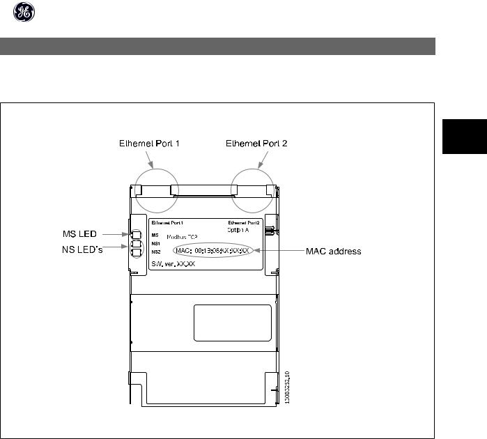
3.1.1 The Modbus TCP Option
3
OPCMBTCP
Illustration 3.1: Overview of the option
7
Modbus TCP
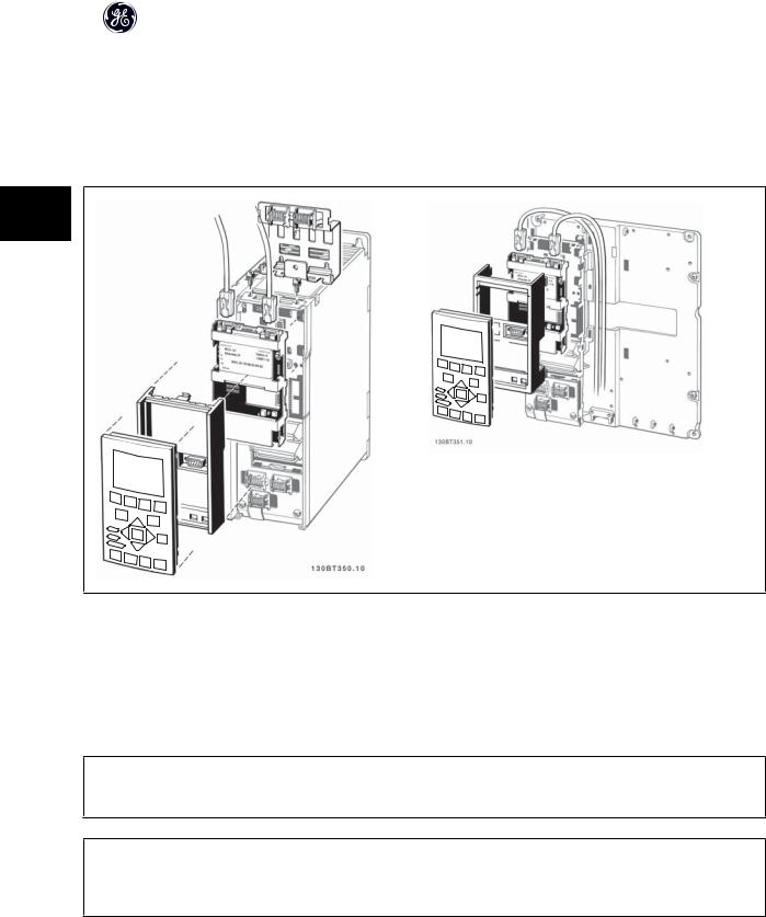
3.1.2 How to Install Option in Frequency Converter
Items required for installing a network option in the frequency converter:
-The network option
-Network option adaptor frame for the AF-650 GP/AF-600 FP. This frame is deeper than the standard frame, to allow space for the network option beneath
-Strain relief (only for unit size 12)
3
Instructions:
-Remove Keypad panel from the AF-650 GP/AF-600 FP.
-Remove the frame located beneath and discard it.
-Push the option into place. The Ethernet connectors must be facing upwards.
-Remove both knock-outs on the network option adaptor frame.
-Push the network option adaptor frame for the AF-650 GP/AF-600 FP into place.
-Replace the Keypad and attach cable
NB!
Do not strip the Ethernet cable and ground it via the strain relief-plate! The grounding of screened Ethernet cable is done through the RJ-45 connector on the option.
NB!
After installing the OPCMBTCP option, be aware of the following parameter settings: par. O-01 Control Site: [2] Controlword only or [0] Digital and ctrl. word
par. O-02 Control Word Source: [3] Option A
8

Modbus TCP
3.1.3 LED Behaviour
The option has 3 bi-coloured LEDs according to ODVA specifications:
|
LED Label |
Description |
|
|
|
|
|
|
|
|
|
|
MS |
Module Status |
|
|
|
|
NS1 |
Network Status Ethernet Port 1 |
|
|
|
|
|
|
|
3 |
|
|
NS2 |
Network Status Ethernet Port 2 |
|||
|
|
|
|
||
|
|
|
|
|
|
The option LED’s operates according to ODVA specifications.
|
|
|
|
|
|
|
|
|
|
|
|
|
|
|
|
|
|
|
|
|
State |
LED |
|
|
|
|
|
|
|
|
|
|
|
|
|
|
|
Description |
|
|
No power |
|
|
|
|
|
|
|
|
|
|
|
|
|
|
|
Off |
The device is un-powered |
|
|
|
|
|
|
|
|
|
|
|
|
|
|
|
|
|
|
|
|
|
|
Device operational |
Green: |
|
|
|
|
|
|
|
|
|
|
|
|
|
|
Solid green |
The device is operational |
|
|
|
|
|
|
|
|
|
|
|
|
|
|
|
|
|||||
|
|
|
|
|
|
|
|
|
|
|
|
|
|
|
|
|
|
|
|
|
Standby |
Green: |
|
|
|
|
|
|
|
|
|
|
|
|
|
|
Flashing green |
The device needs commissioning |
|
|
|
|
|
|
|
|
|
|
|
|
|
|
|
|
|||||
|
|
|
|
|
|
|
|
|
|
|
|
|
|
|
|
|
|
|
|
|
Minor fault |
Red: |
|
|
|
|
|
|
|
|
|
|
|
|
|
|
Flashing red |
The device has detected a recoverable fault |
|
|
|
|
|
|
|
|
|
|
|
|
|
|
|
|
|||||
|
|
|
|
|
|
|
|
|
|
|
|
|
|
|
|
|
|
|
|
|
Major fault |
Red: |
|
|
|
|
|
|
|
|
|
|
|
|
|
|
Solid red |
The device has detected an un-recoverable fault |
|
|
|
|
|
|
|
|
|
|
|
|
|
|
|
|
|||||
|
|
|
|
|
|
|
|
|
|
|
|
|
|
|
|
|
|
|
|
|
Self test |
Red: |
|
|
|
|
|
|
|
|
|
|
|
|
|
|
Flashing red/green |
The Modbus TCP option is in self-test mode |
|
|
|
|
|
|
|
|
|
|
|
|
|
|
|
|
|
||||
|
Green: |
|
|
|
|
|
|
|
|
|
|
|
|
|
|
|
|||
|
|
|
|
|
|
|
|
|
|
|
|
|
|
|
|
|
|
|
|
|
|
|
|
|
|
|
|
|
|
|
|
|
|
|
|
|
|
|
|
|
|
|
|
|
|
|
|
|
|
|
|
|
|
|
|
|
|
|
|
|
No IP address |
Yellow |
|
|
|
|
|
|
|
|
|
|
|
|
|
|
Steady yellow |
No IP address configured or obtained |
|
|
|
|
|
|
|
|
|
|
|
|
|
|
|
|
|||||
|
|
|
|
|
|
|
|
|
|
|
|
|
|
|
|
|
|
|
|
|
Wink |
Yellow |
|
|
|
|
|
|
|
|
|
|
|
|
|
|
Flashing yellow |
Flash for 20 seconds |
|
|
|
|
|
|
|
|
|
|
|
|
|
|
|
|
|||||
|
|
|
|
|
|
|
|
|
|
|
|
|
|
|
|
|
|
|
|
Table 3.1: MS: Module Status |
|
|
|
|
|
|
|
|
|
|
|
|
|
|
|
|
|
|
|
State |
LED |
|
|
|
|
|
|
|
|
|
|
|
|
|
|
|
Description |
|
No IP-address (no power) |
|
|
|
|
|
|
|
|
|
|
|
|
|
|
|
|
Off |
No link present (or is un-powered) |
|
|
|
|
|
|
|
|
|
|
|
|
|
|
|
|
|
|
|
Connected |
Green: |
|
|
|
|
|
|
|
|
|
|
|
|
|
|
|
Solid green |
There is established (at least) one CIP connection to |
|
|
|
|
|
|
|
|
|
|
|
|
|
|
|
the device |
|||
|
|
|
|
|
|
|
|
|
|
|
|
|
|
|
|
|
|
|
|
|
|
|
|
|
|
|
|
|
|
|
|
|
|
|
|
|
|
Duplicate IP |
Red: |
|
|
|
|
|
|
|
|
|
|
|
|
|
|
|
Solid red |
The IP-address assigned to the device is already in |
|
|
|
|
|
|
|
|
|
|
|
|
|
|
|
use |
|||
|
|
|
|
|
|
|
|
|
|
|
|
|
|
|
|
|
|
|
|
|
|
|
|
|
|
|
|
|
|
|
|
|
|
|
|
|
|
Self test |
Red: |
|
|
|
|
|
|
|
|
|
|
|
|
|
|
|
Flashing red/green |
The Modbus TCP is in self-test mode |
|
|
|
|
|
|
|
|
|
|
|
|
|
|
|
||||
Green |
|
|
|
|
|
|
|
|
|
|
|
|
|
|
|
|||
|
|
|
|
|
|
|
|
|
|
|
|
|
|
|
|
|
|
|
|
|
|
|
|
|
|
|
|
|
|
|
|
|
|
|
|
|
|
|
|
|
|
|
|
|
|
|
|
|
|
|
|
|
|
|
|
|
Device has been winked |
Yellow |
|
|
|
|
|
|
|
|
|
|
|
|
|
|
|
Flashing yellow |
Flash for 20 seconds |
|
|
|
|
|
|
|
|
|
|
|
|
|
|
|||||
|
|
|
|
|
|
|
|
|
|
|
|
|
|
|
|
|
|
|
Link present at 10 Mbps |
Yellow |
|
|
|
|
|
|
|
|
|
|
|
|
|
|
Steady yellow |
Link present; but nor winked and no ACD |
|
|
|
|
|
|
|
|
|
|
|
|
|
|
||||||
Table 3.2: NS1 + NS2: Network Status (one per port)
9

Modbus TCP
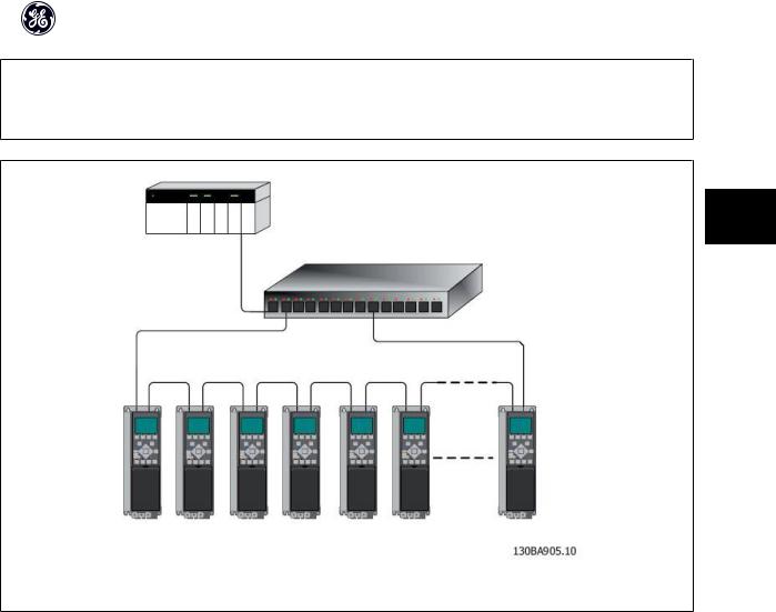
3.1.4 Topology
The OPCMBTCP features a build-in Ethernet-switch, thus having two Ethernet RJ-45 connectors. This enables the possibility for connecting several Modbus TCP options in a line topology as an alternative to the typical star-topology.
The two ports are equal, in the sense that they are transparent for the option. If only one connector is used, either port can be used.
3
Illustration 3.2: Star topology
Illustration 3.3: Line topology
NB!
For line topology please refer to section: “Recommended design rules” In a line topology all drives must be powered, either by mains or by their 24 V DC option cards, for the build-in switch to work.
10
Modbus TCP
NB!
Please observe that mounting drives of different power-sizes in a line topology may result in unwanted power-off behaviour.
Smaller drives discharge faster than bigger drives. This can result in loss of link in the line topology, which may lead to control word timeout. To avoid this, mount the drives with the longest discharge time first in the line topology.
3
Illustration 3.4: Ring/redundant line topology
3.1.5 Network
It is of high importance that the media chosen for Ethernet data transmission are suitable. Usually CAT 5e and 6 cables are recommended for industrial applications. Both types of cable are available as Unshielded Twisted Pair and Shielded Twisted Pair. Generally shielded cables are recommended for use in industrial environments and with frequency converters.
A maximum cable-length of 100 m is allowed between switches.
Optical fibres can be used for gapping longer distances and providing galvanic isolation.
For connecting Modbus TCP devices both hubs and switches can be used. It is, however, recommended always to use suitable industrial graded Ethernet switches. For more information regarding IP-switching, please refer to section: IP Traffic in this manual.
11

Modbus TCP
3.1.6 Recommended Design Rules
While designing Ethernet networks special attention and caution must be taken regarding active network components.
While designing a network for line topology it is important to notice that a small delay is added with each every switch in the line.
It is not recommended to connect more than 32 drives in a line at any API. Exceeding the recommended design rules, may result in failing communication.
3
12

Modbus TCP
3.1.7 EMC Precautions
The following EMC precautions are recommended in order to achieve interference-free operation of the Ethernet network. Additional EMC information is available in the AF-650 GP/AF-600 FP series Design Guide.
NB!
Relevant national and local regulations, for example regarding protective earth connection, must be observed.
The Ethernet communication cable must be kept away from motor and brake resistor cables to avoid coupling of high frequency noise from one cable to the 3 other. Normally a distance of 200 mm (8 inches) is sufficient, but maintaining the greatest possible distance between the cables is recommended, especially where
cables run in parallel over long distances. When crossing is unavoidable, the Ethernet cable must cross motor and brake resistor cables at an angle of 90 degrees.
13

Modbus TCP
4
14

Modbus TCP
4 How to Configure
4.1.1 IP Settings
All IP-related parameters are located in parameter group EN-##:
|
EN-00 |
IP Address Assignment |
|
|
|
|
|
|
|
|
|
|
EN-01 |
IP Address |
|
|
|
|
EN-02 |
Subnet Mask |
|
|
4 |
|
|
|
|
|
|
|
EN-03 |
Default Gateway |
|||
|
|
|
|
||
|
EN-04 |
DHCP Server |
|
|
|
|
|
|
|
|
|
|
EN-05 |
Lease Expires |
|
|
|
|
EN-06 |
Name Servers |
|
|
|
|
|
|
|
|
|
|
EN-07 |
Domain Name |
|
|
|
|
EN-08 |
Host Name |
|
|
|
|
|
|
|
|
|
|
EN-09 |
Physical Address |
|
|
|
|
|
|
|
|
|
The OPCMBTCP option offers several ways of IP address assignment.
Setting up drive with manual assigned IP address:
|
Par. |
Name |
Value |
|
|
|
|
|
|
|
EN-00 |
IP Address Assignment |
[0] MANUAL |
|
|
EN-01 |
IP Address |
192.168.0.xxx* |
|
|
|
|
|
|
|
EN-02 |
Subnet Mask |
255.255.255.0* |
|
|
EN-03 |
Default Gateway |
optional |
|
|
|
|
|
|
*= Class C IP address example. Any valid IP address can be entered.
NB!
A power-cycle is necessary after setting the IP parameters manually.
Setting up drive with automatic (BOOTP/DHCP) assigned IP address:
|
Par. |
Name |
Value |
|
|
|
|
|
|
|
EN-00 |
IP Address Assignment |
[1] DHCP/[2] BOOTP |
|
|
EN-01 |
IP Address |
Read only |
|
|
|
|
|
|
|
EN-02 |
Subnet Mask |
Read only |
|
|
EN-03 |
Default Gateway |
Read only |
|
|
|
|
|
|
By IP address assigned by DHCP/BOOTP server, the assigned IP Address and Subnet Mask can be read out in par. EN-01 and EN-02. In par. EN-04 DHCP Server, the IP address of the found DHCP or BOOTP server is displayed. For DHCP only: The remaining lease-time can be read-out in par. EN-05 Lease Expires.
Par. EN-09, Physical Address reads out the MAC address of option, which is also printed on the label of the option. If using fixed leases together with DHCP or BOOTP, the physical MAC address is linked with a fixed IP address.
NB!
If no DHCP or BOOTP reply has been received after 4 attempts (e.g. if the DHCP/BOOTP server has been powered off), the option will fallback to the last good known IP address.
15

Modbus TCP
Par. EN-03, Default Gateway is optional and only used in routed networks.
Par. EN-06, Name Servers
Par. EN-07, Domain Name Par. EN-08, Host Name
Are used with Domain Name Server systems and are all optional. If DHCP or BOOTP is selected as IP address assignment, these parameters are read only.
NB!
It is only possible to assign valid class A, B and C IP address to the option. The valid ranges are shown in the below table:
4 |
|
|
|
|
|
|
Class A |
1.0.0.1 - 126.255.255.254 |
|
||
|
|
|
|
||
|
|
|
|
|
|
|
|
|
Class B |
128.1.0.1 - 191.255.255.254 |
|
|
|
|
Class C |
192.0.1.1 - 223.255.254.254 |
|
|
|
|
|
|
|
4.1.2 Ethernet Link Parameters
Parameter group EN-1# holds information Ethernet Link information:
|
EN-10 |
Link Status |
|
|
|
|
|
|
EN-11 |
Link Duration |
|
|
EN-12 |
Auto Negotiation |
|
|
|
|
|
|
EN-13 |
Link Speed |
|
|
EN-14 |
Link Duplex |
|
|
|
|
|
Please note the Ethernet Link Parameters are unique per port.
Par. EN-10, Link Status and par. EN-11, Link Duration displays information on the link status, per port.
Par. EN-10, Link Status will display Link or No Link according to the status of the present port.
Par. EN-11, Link Duration will display the duration of the link on the present port. If the link is broken the counter will be reset.
Par. EN-12, Auto Negotiation – is a feature that enables two connected Ethernet devices to choose common transmission parameters, such as speed and duplex mode. In this process, the connected devices first share their capabilities as for these parameters and then choose the fastest transmission mode they both support.
By default this function is enabled.
Incapability between the connected devices, may lead to decreased communication performance. To prevent this, Auto Negotiation can be disabled.
If par. EN-12 is set to OFF, link speed and duplex mode can be configured manually in par. EN-13 and EN-14.
Par. EN-12, Link Speed – displays/sets the link speed per port. “None” is displayed if no link is present.
Par. EN-14, Link Duplex – displays/sets the duplex mode per port.
Half-duplex provides communication in both directions, but only in one direction at a time (not simultaneously).
Full-duplex allows communication in both directions, and unlike half-duplex, allows for this to happen simultaneously.
16
 Loading...