


PANOPTIX™ LIVESCOPE™
LVS32-TH
INSTALLATION
INST•UCTIONS
Important Safety Information
 WARNING
See the Important Safety and Product Information guide in the product box for product warnings and other important information.
The device must be installed with at least one of the included anti-rotation bolts. Failure to do so could result in the device rotating while the boat is moving and could cause damage to your vessel.
You are responsible for the safe and prudent operation of your vessel. Sonar is a tool that enhances your awareness of the water beneath your boat. It does not relieve you of the responsibility of observing the water around your boat as you navigate.
 CAUTION
Failure to install and maintain this equipment in accordance with these instructions could result in damage or injury.
Always wear safety goggles, ear protection, and a dust mask when drilling, cutting, or sanding.
NOTICE
When drilling or cutting, always check what is on the opposite side of the surface.
To obtain the best performance and to avoid damage to your boat, you must install the Garmin® transducer according to these instructions.
Read all installation instructions before proceeding with the installation. If you experience difficulty during the installation, contact Garmin Product Support.
Registering Your Device
Help us better support you by completing our online registration today. Keep the original sales receipt, or a photocopy, in a safe place.
1 Go to my.garmin.com/registration.
2 Sign in to your Garmin account.
Software Update
You must update the software when you install this device.
If your Garmin chartplotter has Wi Fi® technology, you should update the software using the ActiveCaptain™ app on a compatible Android™ or Apple® device. If your chartplotter does not have has Wi Fi technology, you should update the software using a memory card and a Windows® computer.
For more information, go to support.garmin.com.
Tools Needed
•Drill
•3 mm bit (1/8 in.)
•9 mm bit (3/8 in.)
•12 mm bit (1/2 in.) (metal hull)
•13 mm bit (1/2 in.) (fiberglass hull)
•32 mm spade bit (11/4 in.) (fiberglass hull)
•38 mm hole saw (1 1/2 in.) (metal hull)
•Bandsaw or table saw
•Slip-joint pliers or crescent wrench
•Masking tape
•Marine sealant
•Solvent wash
•Marine-grade epoxy or exposed core sealant that can be used on plastic (cored fiberglass hull)
About the Transducer
The transducer transmits and receives sound waves through the water, and relays sound-wave information to your Garmin sonar device.
Mounting Location Considerations
•On outboard and sterndrive vessels  , the transducer should be mounted in front of and close to the engine or engines.
•On inboard vessels  , the transducer should be mounted in front of and far away from the engine propeller and shaft.
•On step-hull vessels  , the transducer should be mounted in front of the first step.
•On full-keel vessels  , the transducer should be mounted at a slight angle that aims at the bow, not parallel to the centerline.
•On fin-keel vessels  , the transducer should be mounted from 25 cm to 75 cm (from 10 to 30 in.) in front of the keel and a maximum of 10 cm (4 in.) to the side of the centerline.
•On vessels with displacement hulls  , the transducer should be mounted approximately 1/3 aft of the waterline length of the vessel from the bow, and from 150 to 300 mm (from 6 to 12 in.) to the side of the centerline.
•The transducer should be mounted parallel to the bow-stern axis of your vessel.
•The transducer should not be mounted behind strakes, struts, fittings, water intake or discharge ports, or anything that creates air bubbles or causes the water to become turbulent.
The transducer must be in clean (non-turbulent) water for optimal performance.
•The transducer should not be mounted in a location where it might be jarred when launching, hauling, or storing.
•On single-drive boats, the transducer must not be mounted in the path of the propeller.
The transducer can cause cavitation that can degrade the performance of the boat and damage the propeller.
•On twin-drive boats, the transducer should be mounted between the drives, if possible.
January 2019 190-02496-90_0A

Mounting Considerations
•You must install the sonar module in a location with adequate ventilation where it will not be exposed to extreme temperatures.
•You should mount the transducer in a location where it will not be jarred when launching, hauling, or storing.
•You should mount the transducer in a location where it is not behind strakes, struts, fittings, water intake or discharge ports, thru-hull transducers, or anything that creates air bubbles or causes the water to become turbulent. Turbulent water may interfere with the sonar beam.
•You should mount the transducer in a location where there are no bulkheads or stringers on the interior of the boat that impede a clear surface for the fairing block.
•You should mount the transducer as close to the center line of the boat as possible.
•When mounted farther from the center of the transom, a greater deadrise can cause the boat hull  to interfere with the sonar beam
  , and can cause inconsistent detection on
the opposite side of the boat  . These illustrations show the transducer ifrom behind.
•On single-drive vessels, you must not mount the transducer in the path of the propeller.
•On twin-drive vessels, you should mount the transducer between the drives, if possible.
•You should mount the sonar module in a location where the LEDs are visible.
•You should mount the sonar module in a location where the cables can be easily connected.
Fairing Block Angle Cut
A fairing block positions your transducer parallel to the water line for increased sonar accuracy. You must measure the deadrise angle of your boat hull to determine if a fairing block is necessary to mount the transducer. If the deadrise angle of your mounting location exceeds 5°, you should use a fairing block to mount the transducer.
Deadrise Angle
Deadrise is the angle formed between a horizontal line and a boat hull at a single point. You can measure the deadrise angle with a smartphone application, an angle finder, a protractor, or a digital level. You can also ask your boat manufacturer for the deadrise angle of the specific point on your boat hull.
NOTE: A boat may have several deadrise angles depending on the shape of the hull. Measure the deadrise angle only at the location where you plan to install the transducer.
Cutting the Fairing Block
 CAUTION
Always wear safety goggles, ear protection, and a dust mask when drilling, cutting, or sanding.
1Using wood screws, attach the fairing block to a piece of wood.
The wood becomes a cutting guide for the fairing block.
2Measure the deadrise angle of the hull at the mounting location.
3Tilt your table saw blade  to match the deadrise angle and secure the cutting fence.
4Position the fairing block on the table so the cutting guide
rests against the fence  and the angle matches the angle of the mounting location.
5Adjust the cutting fence to ensure the fairing block  has a minimum thickness
  of 2 mm (1/16 in.).
NOTE: The maximum cutting angle  of the fairing block is 25°.
6 Cut the fairing block.
7Using a rasp or power tool, shape the fairing block to the hull as precisely as possible.
8Use the remaining section of the fairing block as the backing block inside the hull.
Mounting the Sonar Module
Mounting the Panoptix LiveScope GLS 10 Device
NOTICE
If you are mounting the device in fiberglass, when drilling the pilot holes, it is recommended to use a countersink bit to drill a clearance counterbore through only the top gel-coat layer. This will help to avoid cracking in the gel-coat layer when the screws are tightened.
NOTE: Stainless-steel screws may bind when screwed into fiberglass and overtightened. It is recommended to apply an anti-seize lubricant to the screws before installing them.
NOTE: Screws are included with the device, but they may not be suitable for the mounting surface.
Before you mount the device, you must select a mounting location and determine what screws and other mounting hardware are needed for the surface.
1Place the device in the mounting location and mark the location of the pilot holes.
2 Drill a pilot hole for one corner of the device.
3Loosely fasten the device to the mounting surface with one corner and examine the other three pilot-hole marks.
4Mark new pilot-hole locations if necessary, and remove the device from the mounting surface.
2
5 Drill the remaining pilot holes.
6 Secure the device to the mounting location.
Blink Codes
After the sonar module is installed, it turns on when the chartplotter is turned on. The color status LED on the sonar module indicates its operational status.
LED Color |
State |
Status |
Green |
Blinking |
The sonar module is connected to a |
|
|
chartplotter and is operating properly. |
|
|
You should see sonar data on the |
|
|
chartplotter. |
Red |
Blinking |
The sonar module is turned on, but is |
|
|
not connected to a chartplotter, or is |
|
|
waiting to connect to a chartplotter. If the |
|
|
sonar module is connected to the |
|
|
chartplotter and this code persists, |
|
|
check the wiring connections. |
Orange |
Blinking |
A software update is in progress. |
|
|
|
Red/Green |
Blinking |
Reserved |
Red |
Two blinks |
Other sonar failure. |
|
followed by a 3- |
|
|
second pause |
|
Red |
Three blinks |
The transducer is not detected by the |
|
followed by a 3- |
sonar module. If this code persists, |
|
second pause |
check the wiring connections. |
Red |
Five blinks |
The sonar module input voltage exceeds |
|
followed by a 3- |
the maximum input voltage. |
|
second pause |
|
Cored Fiberglass Boat Hull Installation
Instructions
Installing a Thru-Hull Transducer with a Fairing Block
Drilling the Transducer Stem Hole and the Anti-Rotation Bolt Hole in a Cored Fiberglass Hull
Before you can drill the hole for the anti-rotation bolt, you must drill the hole for the transducer stem (Drilling the Transducer Stem Hole and the Anti-Rotation Bolt Hole in a Cored Fiberglass Hull, page 3) and you must cut the fairing block (Cutting the Fairing Block, page 2).
The core must be cut and sealed carefully to protect against water seepage.
1Select a mounting location without surface irregularities or obstructions.
2Using the template, mark the location of the stem hole and anti-rotation bolt.
3Drill a 3 mm (1/8 in.) pilot hole through the template and hull at the stem hole location.
The hole must be perpendicular to the water surface.
4Place masking tape over the pilot hole and surrounding area outside the hull to prevent damage to the fiberglass.
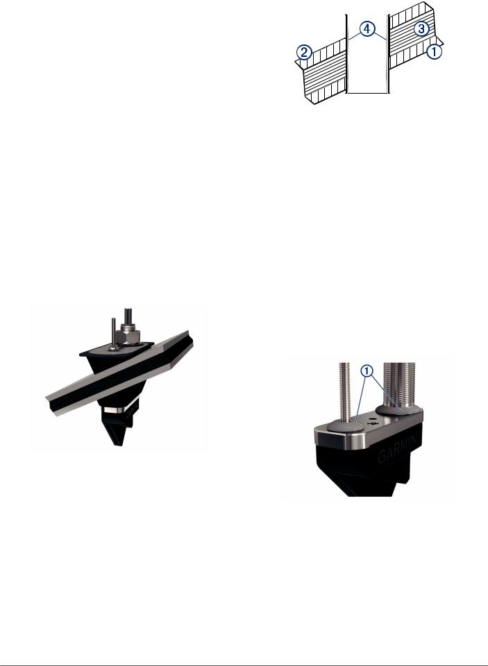
5Using a 32 mm (1 1/4 in.) bit at the stem hole location, drill from outside the hull through the outer skin  , inner skin
  , and the core
  .
.
The hole must be perpendicular to the water surface.
6Sand and clean the inner skin, core, and outer skin around the hole.
7Seal the exposed inner core with epoxy  , and allow the epoxy to set thoroughly.
8While holding a drill with a 9 mm (3/8 in.) bit plumb, drill the anti-rotation bolt hole through the hull from outside the hull. The hole must be perpendicular to the water surface.
9Sand and clean the area around the hole with a solvent wash to remove dust particles.
Applying Marine Sealant to a Thru-Hull Transducer
You must apply marine sealant to the transducer to ensure a tight, waterproof seal between the fairing block and the hull. Do not apply sealant directly to the stem or anti-rotation bolt.
Apply marine sealant  around the base of the stem and anti-rotation bolt on the transducer.
Installing the Transducer with a Fairing Block
It is recommended that two installers complete these instructions, with one positioned outside the boat and one inside the boat.
NOTE: When installing the transducer in a cored fiberglass hull, avoid over-tightening the nuts to prevent damaging the hull.
1Apply marine sealant at the base of the anti-rotation bolt  and transducer stem
  .
.
3
 Loading...