


GTX 345R
Table of contents
 Loading...
190-00734-11 September 2019 Revision 7
GTX 33X and GTX 3X5 ADS-B
Maintenance Manual
Contains Instructions for Continued Airworthiness for
STC SA01714WI
Aircraft make, model, registration number, and serial
number and accompanying STC configuration
information in Appendix A must be completed and saved
with aircraft permanent records.

190-00734-11 GTX 33X and GTX 3X5 ADS-B Maintenance Manual
Rev. 7 Page i
© 2013-2019 Garmin International or its subsidiaries
All Rights Reserved
Except as expressly provided herein, no part of this manual may be reproduced, copied, transmitted,
disseminated, downloaded or stored in any storage medium, for any purpose without the express prior
written consent of Garmin. Garmin hereby grants permission to download a single copy of this manual and
of any revision to this manual onto a hard drive or other electronic storage medium to be viewed and to
print one copy of this manual or of any revision hereto, provided that such electronic or printed copy of this
manual or revision must contain the complete text of this copyright notice and provided further that any
unauthorized commercial distribution of this manual or any revision hereto is strictly prohibited.
Garmin
®
is a registered trademark of Garmin International or its subsidiaries. GDU
™
and GTN
™
are
trademarks of Garmin International or its subsidiaries. These trademarks may not be used without the
express permission of Garmin.
Adobe
®
is a registered trademark of Adobe Systems Incorporated. All rights reserved.
The Bluetooth word mark and logos are registered trademarks owned by Bluetooth SIG, Inc. and any use
of such marks by Garmin is under license. Other trademarks and trade names are those of their respective
owners.
At Garmin, we value your opinion.
For comments about this guide, please e-mail Techpubs.Salem@garmin.com
For comments about Garmin aviation products, email Avionics@garmin.com
.
Garmin International, Inc.
1200 E. 151st Street
Olathe, KS 66062 USA
Telephone: (913) 397-8200
www.garmin.com
Garmin (Europe) Ltd.
Liberty House, Bulls Copse Road
Hounsdown Business Park
Southampton, SO40 9LR, UK
Phone: +44 (0) 23 8052 4000
Fax: +44 (0) 23 8052 4004
Garmin AT, Inc.
2345 Turner Rd., SE
Salem, OR 97302 USA
Telephone: (503) 581-8101

190-00734-11 GTX 33X and GTX 3X5 ADS-B Maintenance Manual
Rev. 7 Page ii
RECORD OF REVISIONS
CURRENT REVISION DESCRIPTION
Revision
Revision
Date
Description
5 10/05/16
Updated the standard rack part number.
Moved GPS keep alive input requirement to optional interface.
Updated main and ADS-B software to v2.05
6 12/08/17
Updated GTX 33/330 software to v8.04
Updated GTX 3X5 main software to v2.12 and ADSB software to v2.10
Added models to bonding table B-1
7
09/09/19
Added Diversity unit part numbers and descriptions.
Section Description
1.6.1 Updated to add Diversity units to section.
2 Added Diversity units to list of GTX 3X5 models.
2.3
Updated to add Diversity units to section.
Updated Figure 2-3 to include GTX 335D and GTX 335DR units.
2.4
Updated to add Diversity units to section.
Updated Figure 2-4 to include GTX 345D and GTX 345DR units.
2.5
Updated to add Diversity units to section.
Updated Figure 2-5 to include GTX 335DR and GTX 345DR units.
2.6 Added GTX 335D and GTX 345D to Table 2-1 GTX Electrical Load.
3 Updated to add Diversity units to section.
3.2 Updated to add Diversity units to section.
3.3 Updated to add Diversity units to section.
3.4 Updated to add Diversity units to section.
4.5 Updated to add Diversity units to section.
4.6 Updated to add Diversity units to section.
5.4.2 Added GTX 345D and GTX 345DR to include the J3252 connector.
5.4.4
Added “ADS-B OUT FUNCTION FAIL”, “STANDBY ALERT”, “TRANSPONDER
ACTIVE”, and “DIVERSITY FAIL” pins to Table 5-9 GTX 3X5/3X5R Discrete Outputs.
Changed “AUDIO INHIBIT #1” pin to “AUDIO MUTE” in Table 5-11 GTX 3X5/3X5R
Discrete Inputs.
Changed “AUDIO INHIBIT #2” pin to “AUDIO CANCEL” in Table 5-11 GTX 3X5/3X5R
Discrete Inputs.
Added “TRAFFIC AUDIO MUTE” and “TRAFFIC AUDIO CANCEL” pins in Table 5-11
GTX 3X5/3X5R Discrete Inputs.

190-00734-11 GTX 33X and GTX 3X5 ADS-B Maintenance Manual
Rev. 7 Page iii
6.3
Added Table 6-4 and Figure 6-9 GTX 3X5D with Backplate Assembly (P/N 011-04340-
02).
Added Table 6-5 and Figure 6-10 GTX 3X5DR with Backplate Assembly (P/N 011-
04340-10).
6.3.1 Updated to add Diversity units to section.
6.3.2 Updated to add Diversity units to section.
6.3.3 Updated to add Diversity units to section.
8.4.1 Updated to add Diversity units to section.
8.4.2 Updated to add Diversity units to section.
8.5.2 Updated to add Diversity units to section.
8.6 Corrected “Part 23” to “Part 43”.
8.8 Updated to add Diversity units to section.
Appendix A
Updated to add Diversity units to section. Added Diversity sections to Post-Installation
Configuration Log.
Section Description
190-00734-11 GTX 33X and GTX 3X5 ADS-B Maintenance Manual
Rev. 7 Page iv
INFORMATION SUBJECT TO EXPORT CONTROL LAWS
This document may contain information that is subject to the Export Administration Regulations (EAR)
issued by the United States Department of Commerce (15 CFR, Chapter VII, Subchapter C) and may not
be exported, released, or disclosed to foreign nationals inside or outside of the United States without first
obtaining an export license. A violation of the EAR may be subject to a penalty of up to 10 years
imprisonment and a fine of up to $1,000,000 under Section 2410 of the Export Administration Act of 1979.
Include this notice with any reproduced portion of this document.
This information in this document is subject to change without notice. Visit Garmin’s Dealer Resource
Center for current updates and supplemental information concerning the operation of Garmin products.
DEFINITIONS OF WARNINGS, CAUTIONS, AND NOTES
WARNING
This product, its packaging, and its components contain chemicals known to the State of
California to cause cancer, birth defects, or reproductive harm. This notice is being
provided in accordance with California's Proposition 65. If you have any questions or
would like additional information, please refer to our website at
www.garmin.com/prop65.
WARNING
Perchlorate Material - special handling may apply. Refer to
www.dtsc.ca.gov./hazardouswaste/perchlorate.
CAUTION
The GTX 330/330D and GTX 335/345 units have a special anti-reflective coated display
that is sensitive to waxes and abrasive cleaners. CLEANERS CONTAINING AMMONIA
WILL HARM THE ANTI-REFLECTIVE COATING. It is important to clean the display
using a clean, lint-free cloth, with a cleaner that is safe for anti-reflective coatings.
WARNING
Warnings indicate that immediate attention must be given to avoid potential
equipment damage and personal injury should the instructions be disregarded.
CAUTION
Cautions indicate an alert to potential damage to the equipment if the
procedural step is not directly followed.
NOTE
Notes indicate additional information is needed.

190-00734-11 GTX 33X and GTX 3X5 ADS-B Maintenance Manual
Rev. 7 Page v
TABLE OF CONTENTS
1 INTRODUCTION..............................................................................................................................1-1
1.1 Content, Scope, Purpose.............................................................................................................1-2
1.2 Organization ...............................................................................................................................1-2
1.3 Applicability...............................................................................................................................1-3
1.4 Publications ................................................................................................................................1-3
1.5 Revision and Distribution...........................................................................................................1-3
1.6 Reference....................................................................................................................................1-4
2 SYSTEM DESCRIPTION.................................................................................................................2-1
2.1 GTX 330/330D...........................................................................................................................2-2
2.2 GTX 33/33D...............................................................................................................................2-4
2.3 GTX 335/335D/335R/335DR ....................................................................................................2-6
2.4 GTX 345/345D/345R/345DR ....................................................................................................2-8
2.5 GTX 335R/335DR/345R/345DR with Legacy G1000 ............................................................2-10
2.6 Electrical Load Information .....................................................................................................2-11
3 GTX CONTROL AND OPERATION.............................................................................................3-1
3.1 GTX 330/330D...........................................................................................................................3-2
3.2 GTX 335/335D/345/345D..........................................................................................................3-4
3.3 GTX 33/33D and GTX 335R/335DR/345R/345DR..................................................................3-7
3.4 GTX 335R/335DR/345R/345DR with Legacy G1000 ..............................................................3-8
3.5 GTX 3X5 Install Tool ..............................................................................................................3-10
4 INSTRUCTIONS FOR CONTINUED AIRWORTHINESS.........................................................4-1
4.1 Applicability...............................................................................................................................4-2
4.2 Airworthiness Limitations..........................................................................................................4-2
4.3 Servicing Information ................................................................................................................4-3
4.4 Maintenance Intervals ................................................................................................................4-4
4.5 Visual Inspection........................................................................................................................4-5
4.6 Electrical Bonding Test..............................................................................................................4-7
4.7 Additional Instructions...............................................................................................................4-7
5 TROUBLESHOOTING ....................................................................................................................5-1
5.1 GTX General Troubleshooting...................................................................................................5-2
5.2 GTX Failure Annunciations .......................................................................................................5-4
5.3 GTX 33X Connector Pinout Information.................................................................................5-11
5.4 GTX 3X5 Connector Pinout Information.................................................................................5-15
6 UNIT REMOVAL AND RE-INSTALLATION..............................................................................6-1
6.1 GTX 330/330D...........................................................................................................................6-2
6.2 GTX 33/33D...............................................................................................................................6-4
6.3 GTX 3X5....................................................................................................................................6-5
6.4 Transponder Antenna ...............................................................................................................6-19
7 SOFTWARE.......................................................................................................................................7-1
7.1 Software Check ..........................................................................................................................7-2
7.2 GTX 33/330 Software Update....................................................................................................7-5
7.3 GTX 3X5 Software Update........................................................................................................7-7
8 SYSTEM CONFIGURATION AND CHECKOUT .......................................................................8-1
8.1 Overview ....................................................................................................................................8-2
8.2 System Checkout........................................................................................................................8-2
8.3 GTX 33/330 Configuration ........................................................................................................8-3
8.4 GTX 3X5 Configuration ............................................................................................................8-4
8.5 GTX Airborne Test Mode ..........................................................................................................8-5

190-00734-11 GTX 33X and GTX 3X5 ADS-B Maintenance Manual
Rev. 7 Page vi
8.6 Regulatory Test ..........................................................................................................................8-7
8.7 ADS-B Out Test .........................................................................................................................8-8
8.8 GTX 3X5 with TCAS System Test (GX000 Only) ...................................................................8-9
9 SYSTEM RETURN TO SERVICE PROCEDURE........................................................................9-1
9.1 Maintenance Records .................................................................................................................9-1
APPENDIX A INSTALLATION SPECIFIC INFORMATION ........................................................A-1
APPENDIX B SPECIAL BONDING PROCEDURES.......................................................................B-1
B.1 Considerations for Untreated or Bare Dissimilar Metals ..........................................................B-2
B.2 Preparation of Aluminum Surfaces ........................................................................................... B-5
B.3 Composite Aircraft.................................................................................................................... B-6
B.4 Tube-and-Fabric Aircraft ........................................................................................................ B-10
B.5 Bonding Jumper ...................................................................................................................... B-12

190-00734-11 GTX 33X and GTX 3X5 ADS-B Maintenance Manual
Rev. 7 Page vii
LIST OF FIGURES
Figure 2-1 GTX 330 or GTX 330D Interface Summary ........................................................................2-3
Figure 2-2 GTX 33 or GTX 33D Interface Summary ............................................................................2-5
Figure 2-3 GTX 335/335D/335R/335DR Interface Summary ...............................................................2-7
Figure 2-4 GTX 345/345D/345R/345DR Interface Summary ...............................................................2-9
Figure 2-5 GTX 335R/335DR/345R/345DR Interface Summary with Legacy G1000 .......................2-10
Figure 3-1 GTX 330/330D Front Panel ..................................................................................................3-2
Figure 3-2 GTX 335/335D/345/345D Front Panel ................................................................................3-4
Figure 3-3 GTN 7XX Transponder Control ...........................................................................................3-7
Figure 3-4 GTN 6XX Transponder Control ...........................................................................................3-7
Figure 3-5 GNS 480 Transponder Control .............................................................................................3-7
Figure 3-6 G1000 Transponder Control .................................................................................................3-9
Figure 3-7 G1000 Transponder Control .................................................................................................3-9
Figure 3-8 USB A and USB B Connectors ..........................................................................................3-10
Figure 3-9 GTX 3X5 State Page ..........................................................................................................3-11
Figure 3-10 GTX 3X5 Status Page .........................................................................................................3-12
Figure 3-11 GTX 3X5 Configuration Group ..........................................................................................3-13
Figure 3-12 GTX 3X5 Diagnostics Group .............................................................................................3-14
Figure 3-13 GTX 3X5 Product Data Group ...........................................................................................3-15
Figure 5-1 GTX (All Models) Transponder Troubleshooting ................................................................5-3
Figure 5-2 GTX 330/330D Transponder Failure/Fault Messages ..........................................................5-4
Figure 5-3 GTX 33/33D Transponder Failure/Fault Messages ..............................................................5-5
Figure 5-4 GTX 3X5 Transponder Alerts ..............................................................................................5-6
Figure 5-5 Rear View, Connector P3301 .............................................................................................5-11
Figure 5-6 GTX 33/330 ARINC 429 Connections ...............................................................................5-14
Figure 5-7 Rear View, Connector J3251 ..............................................................................................5-15
Figure 5-8 Rear View, Connector J3252 ..............................................................................................5-17
Figure 6-1 GTX 330 Mounting Rack/Connector Assembly ..................................................................6-3
Figure 6-2 GTX 33 Mounting Rack/Connector Assembly ....................................................................6-4
Figure 6-3 GTX 3X5 Connector Kits .....................................................................................................6-5
Figure 6-4 GTX 3X5 without GPS Back Plate Assembly (P/N 011-02976-00) ....................................6-6
Figure 6-5 GTX 3X5 with GPS Back Plate Assembly (P/N 011-02976-01) .........................................6-6
Figure 6-6 GTX 3X5 Vertical Mount without GPS, Back Plate Assem
bly (P/N 011-02976-10) .........6-7
Figure 6-7 GTX 3X5 Vertical Mount with GPS, Back Plate Assembly (P/N 011-02976-11) ..............6-8
Figure 6-8 GTX 3X5 Vertical Mount with TNC XPDR Back Plate Assembly (P/N 011-02976-12) ...6-8
Figure 6-9 GTX 3X5D with Backplate Assembly (P/N 011-04340-02) ................................................6-9
Figure 6-10 GTX 3X5DR with Backplate Assembly (P/N 011-04340-10) ...........................................6-10
Figure 6-11 GTX 3X5 Mounting Rack/Connector Assembly ...............................................................6-12
Figure 6-12 GTX 3X5R Standard Mounting Rack/Connector Assembly ..............................................6-14
Figure 6-13 GTX 3X5R G1000 Mounting Rack/Connector Assembly .................................................6-14
Figure 6-14 GTX 3X5R Vertical Mounting Rack/Connector Assembly ...............................................6-16
Figure 6-15 Garmin Altitude Encoder with Back Plate Assembly ........................................................6-18
Figure 7-1 GTX 330 Start-Up Screen ....................................................................................................7-2
Figure 7-2 GTX 330 Product Data Page ................................................................................................7-2
Figure 7-3 GTX 3X5 Start-Up Screen ....................................................................................................7-3
Figure 7-4 GTX 3X5 Product Data Page ...............................................................................................7-3
Figure 7-5 GTN 6XX/7XX System Page ...............................................................................................7-3
Figure 7-6 GX000 System Status Page ..................................................................................................7-4
Figure 7-7 Software Update Connection ................................................................................................7-5

190-00734-11 GTX 33X and GTX 3X5 ADS-B Maintenance Manual
Rev. 7 Page viii
Figure 7-8 GTX 3X5 Install Tool Software Upload Page ......................................................................7-8
Figure B-1 Electrical Bonding Preparation – Nut Plate .........................................................................B-2
Figure B-2 Electrical Bonding Preparation – Bolt/Nut Joint .................................................................B-2
Figure B-3 Electrical Bond Preparation – Terminal Lug .......................................................................B-2
Figure B-4 Fiberglass Insulation for Carbon Material ...........................................................................B-6
Figure B-5 Aluminum Tape Joint ..........................................................................................................B-7
Figure B-6 Aluminum Tape Ground Termination ................................................................................. B-8
Figure B-7 Remote GTX Aluminum Tape Installation ......................................................................... B-9
Figure B-8 Electrical Bonding Using Conductive Clamp .................................................................... B-11
Figure B-9 Bonding Strap .................................................................................................................... B-13

190-00734-11 GTX 33X and GTX 3X5 ADS-B Maintenance Manual
Rev. 7 Page ix
LIST OF TABLES
Table 1-1 Reference Documentation ....................................................................................................1-3
Table 2-1 GTX Electrical Load ...........................................................................................................2-11
Table 4-1 Maintenance Intervals ...........................................................................................................4-4
Table 5-1 GTX 33X Pinout .................................................................................................................5-11
Table 5-2 GTX 33X Encoded Altitude Pin Assignments ...................................................................5-13
Table 5-3 GTX 33/330 Discrete Outputs ............................................................................................5-13
Table 5-4 GTX 33/330 Discrete Inputs ...............................................................................................5-14
Table 5-5 GTX 33/330 RS-232 Connections ......................................................................................5-14
Table 5-6 J3251 Pinout .......................................................................................................................5-15
Table 5-7 J3252 Pinout .......................................................................................................................5-17
Table 5-8 GTX 3X5/3X5R Encoded Altitude Pin Assignments ........................................................5-18
Table 5-9 GTX 3X5/3X5R Discrete Outputs ......................................................................................5-19
Table 5-10 GTX 3X5/3X5R Configurable Output Pins .......................................................................5-19
Table 5-11 GTX 3X5/3X5R Discrete Inputs ........................................................................................5-20
Table 5-12 GTX 3X5/3X5R Configurable Input Pins ..........................................................................5-20
Table 5-13 GTX 3X5/3X5R RS-232 Connections ...............................................................................5-21
Table 5-14 GTX 3X5/3X5R ARINC 429 Connections ........................................................................5-21
Table 5-15 GTX 345/345R RS-422 Connections .................................................................................5-21
Table 5-16 GTX 345/345R HSDB Connections ...................................................................................5-22
Table 6-1 GTX 3X5 Connector Kit Hardware ......................................................................................6-5
Table 6-2 Standard/G1000 Mount Back Plate Hardware .....................................................................6-5
Table 6-3 Vertical Mount Back Plate Hardware ...................................................................................6-7
Table 6-4 Standard and G1000 Mount Backplate Hardware ................................................................6-9
Table 6-5 Vertical Mount Backplate Hardware ..................................................................................6-10
Table 6-6 Garmin Altitude Encoder Kit - P/N 011-03080-00 ............................................................6-18
Table 8-1 Ramp Test Pressure Altitude Check Scenario ......................................................................8-9
Table B-1 Ground Plane Definitions and Ground Path Resistance Requirements ...............................B-3
Table B-2 Composite Airframe Bonding Hardware .............................................................................B-7
Table B-3 Tube and Fabric Airframe Bonding Hardware ..................................................................B-10
Table B-4 Airframe Bonding Hardware .............................................................................................B-13

190-00734-11 GTX 33X and GTX 3X5 ADS-B Maintenance Manual
Rev. 7 Page 1-1
1 INTRODUCTION
1.1 Content, Scope, Purpose ...................................................................................................................1-2
1.2 Organization......................................................................................................................................1-2
1.3 Applicability .....................................................................................................................................1-3
1.4 Publications.......................................................................................................................................1-3
1.5 Revision and Distribution .................................................................................................................1-3
1.6 Reference ..........................................................................................................................................1-4
1.6.1 Terminology ...............................................................................................................................1-4
1.6.2 Acronyms ...................................................................................................................................1-4

190-00734-11 GTX 33X and GTX 3X5 ADS-B Maintenance Manual
Rev. 7 Page 1-2
1.1 Content, Scope, Purpose
This document provides Instructions for Continued Airworthiness (ICA) of the GTX 33X and GTX 3X5
with ADS-B functionality installed and compliant to ADS-B Out version 2, under AML STC SA01714WI.
This document satisfies the requirements for continued airworthiness as defined by 14 CFR Part 23.1529
and Appendix G. Information in this document is required to maintain the continued airworthiness of the
GTX 33X and GTX 3X5.
1.2 Organization
The following outline briefly describes the organization of this manual.
Section 2: System Overview
Provides a description of the GTX 33X and GTX 3X5 equipment installed by this STC.
Section 3: Control and Operation
Provides basic control and operation information specifically tailored to maintenance practices.
Section 4: Instructions for Continued Airworthiness
Provides instructions for continued airworthiness of the GTX 33X and GTX 3X5 ADS-B units.
Section 5: Troubleshooting
Provides troubleshooting information to aid in diagnosing and resolving problems with GTX 33X and
GTX 3X5 system equipment.
Section 6: Unit Removal and Reinstallation
Provides instructions for the removal and replacement of GTX 33X and GTX 3X5 ADS-B units.
Section 7: Software
Provides instructions for loading software on GTX 33X and GTX 3X5 ADS-B units.
Section 8: System Configuration and Checkout
Provides instructions for configuring and testing of GTX 33X and GTX 3X5 system equipment.
Section 9: System Return to Service Procedure
Specifies return-to-service procedures to be performed upon completion of maintenance to GTX 33X and
GTX 3X5 system equipment.
Appendix A: Aircraft Specific Information
Provides a template to record aircraft specific installation and configuration data for GTX 33X and
GTX 3X5 system equipment.
Appendix B: Special Bonding Procedures
Provides instructions for achieving an electrical bond with GTX 33X and GTX 3X5 system equipment.

190-00734-11 GTX 33X and GTX 3X5 ADS-B Maintenance Manual
Rev. 7 Page 1-3
1.3 Applicability
This document applies to all aircraft with either the GTX 33X or the GTX 3X5 installed in accordance with
STC SA01714WI. Modification of an aircraft by this Supplemental Type Certificate (STC) obligates the
aircraft operator to include the maintenance information provided by this document in the operator’s
Aircraft Maintenance Manual and the operator’s Aircraft Scheduled Maintenance Program.
1.4 Publications
In addition to this manual, the following documents are recommended to perform maintenance based on
the installed and interfaced equipment. It is the responsibility of the owner/operator to ensure the latest
applicable versions of these documents are used during operation, servicing, or maintenance of the
airplane.
Table 1-1 Reference Documentation
1.5 Revision and Distribution
This document is required for maintaining the continued airworthiness of the aircraft. Garmin Dealers may
obtain the latest revision of this document at the Garmin Dealer Resource Center
, website.
Dealers are notified of manual revision changes via a Garmin Service Bulletin.
Owner and operators may obtain the latest revision of this document at www.flyGarmin.com
or by
contacting a Garmin dealer. Garmin contact information is available at www.flyGarmin.com
.
Document Garmin P/N
GTX 33X and GTX 3X5 ADS-B AML STC Equipment List
005-00734-05
GTN 625/635/650 Pilot’s Guide
190-01004-03
AFMS, GTX 33X and GTX 3X5 AML STC
190-00734-15
GTN 725/750 Pilot’s Guide
190-01007-03
GNS 400W Series Installation Manual
190-00356-08
GNS 500W Series Installation Manual
190-00357-08
GNS 480 (CNX80) Color GPS/NAV/COM Installation Manual
560-0982-01
GNS 480 Pilot’s Guide
190-00502-00
G1000 System Installation Manual
190-00303-00
GTN 6XX/7XX Part 23 AML STC Installation Manual
190-01007-A3
GTX 3XX Part 23 AML STC Installation Manual
190-00734-10

190-00734-11 GTX 33X and GTX 3X5 ADS-B Maintenance Manual
Rev. 7 Page 1-4
1.6 Reference
1.6.1 Terminology
Except where specifically noted, references made to “GTX 33X” or “GTX 3X5” will apply to the
GTX 330/330D/33/33D or GTX 335/335D/335R/335DR/345/345D/345R/345DR, respectively.
ADS-B or ADS-B Out refers to version 2 ADS-B Out only.
ADS-B In refers to TIS-B traffic and FIS-B weather received from ground stations over UAT as well as
ADS-B and ADS-R traffic targets received directly over 1090 MHz or UAT.
Throughout this document references will be made to metallic aircraft. For the purposes of this manual,
metallic aircraft will be those with an aluminum skin. Nonmetallic aircraft refers to all other aircraft
(e.g., wooden aircraft, aircraft with composite skin, or aircraft with tube and fabric construction).
Unless otherwise stated, all units of measure are US standard units.
The term squitter refers to a burst or broadcast of aircraft-tracking data that is transmitted periodically by a
Mode S transponder without interrogation from a controller’s radar.
1.6.2 Acronyms
AC: Advisory Circular ICA: Instructions for Continued Airworthiness
ADC: Air Data Computer ICAO: International Civil Aviation Organization
ADS-B: Automatic Dependent Surveillance -
Broadcast
I/O: Input/Output
AHRS: Attitude Heading Reference System MFD: Multifunction Display
AML: Approved Model List PED: Portable Electronic Device
ATC: Air Traffic Control SBAS: Satellite-Based Augmentation System
ATCRBS: Air Traffic Control Radar Beacon System SPI: Special Position Identifier
EGNOS: European Geostationary Navigation
Overlay Service
SRM: Structural Repair Manual
ES: Extended Squitter STC: Supplemental Type Certificate
FAA: Federal Aviation Administration TAS: Traffic Advisory System
FIS-B: Flight Information System-Broadcast TCAS: Traffic Alert and Collision Avoidance
System
GAE: Garmin Altitude Encoder TIS: Traffic Information Service
GNS: Garmin Navigation System TSO: Technical Standard Order
GNSS: Global Navigation Satellite System UAT: Universal Access Transceiver
GPS: Global Positioning System VSWR: Voltage Standing Wave Ratio
GTN: Garmin Touchscreen Navigator
WAAS: Wide Area Augmentation System
GTX: Garmin Transponder

190-00734-11 GTX 33X and GTX 3X5 ADS-B Maintenance Manual
Rev. 6 Page 2-1
2 SYSTEM DESCRIPTION
2.1 GTX 330/330D .................................................................................................................................2-2
2.2 GTX 33/33D .....................................................................................................................................2-4
2.3 GTX 335/335D/335R/335DR...........................................................................................................2-6
2.4 GTX 345/345D/345R/345DR...........................................................................................................2-8
2.5 GTX 335R/335DR/345R/345DR with Legacy G1000...................................................................2-10
2.6 Electrical Load Information............................................................................................................2-11
Garmin GTX 33X and GTX 3X5 units operate on radar frequencies, receiving ground radar or TCAS
interrogations. The GTX transmits a coded response of pulses to ground-based radar on a frequency of
1090 MHz. Each unit has IDENT capability and replies to ATCRBS Mode A, Mode C and Mode S
All-Call interrogation. The GTX 345/345D/345R/345DR units include ADS-B In which provides TIS-B
and FIS-B data via UAT and 1090 MHz. The GTX 3X5 units offer an optional Garmin altitude encoder to
meet the required barometric pressure altitude source and an optional internal GPS/SBAS source to meet
the required GNSS position source integrity for ADS-B Out.
The Garmin transponders approved by this STC are in the family of GTX 33X and GTX 3X5 transponders.
The ES option of the GTX 33X units provides ADS-B extended squitter functionality.
The GTX 33X models include:
GTX 33
GTX 330
GTX 33D
GTX 330D
The GTX 3X5 units all provide ADS-B Out functionality. GTX 345/345R units provide ADS-B In. The
GTX 3X5 models include:
GTX 335
GTX 335D
GTX 345
GTX 345D
GTX 335R
GTX 335DR
GTX 345R
GTX 345DR
ADS-B technology improves situational awareness and flight safety. A Garmin transponder with ADS-B
capabilities will automatically transmit position, velocity, and heading information to other aircraft and
ground stations. The current air traffic control system depends on a transponder request for pertinent
aircraft information, whereas ADS-B provides automatic transmission of aircraft information without a
request.

190-00734-11 GTX 33X and GTX 3X5 ADS-B Maintenance Manual
Rev. 6 Page 2-2
2.1 GTX 330/330D
GTX 330/330D units are stand alone, panel mounted units that operate through the integrated display.
GTX 330/330D units can be controlled by an external control unit such as the GTN 6XX/7XX or the
GNS 480. They can display TIS-A information on an approved display unit, via an RS-232 digital
interface.
GTX 330/330D units provide the following features.
Mode S transponder
ADS-B Out capability
Entry and display of squawk code and flight ID
Display of pressure altitude
Display of density altitude
Display of outside air temp
Display of flight timers
Audio output
TIS-A traffic output to a compatible display
The transponder annunciates when the unit has an ADS-B Out failure to alert the crew that the unit has a
degraded ADS-B system.
GTX 330/330D units communicate through the following interfaces.
ARINC 429
RS-232
Gray code
Discrete I/O
Power is provided by the aircraft’s existing avionics bus. Non-diversity GTX 330 units interface with a
transponder antenna mounted to the bottom of the fuselage. GTX 330D diversity units interface to a
transponder antenna mounted to the top of the fuselage as well as the antenna mounted to the bottom.
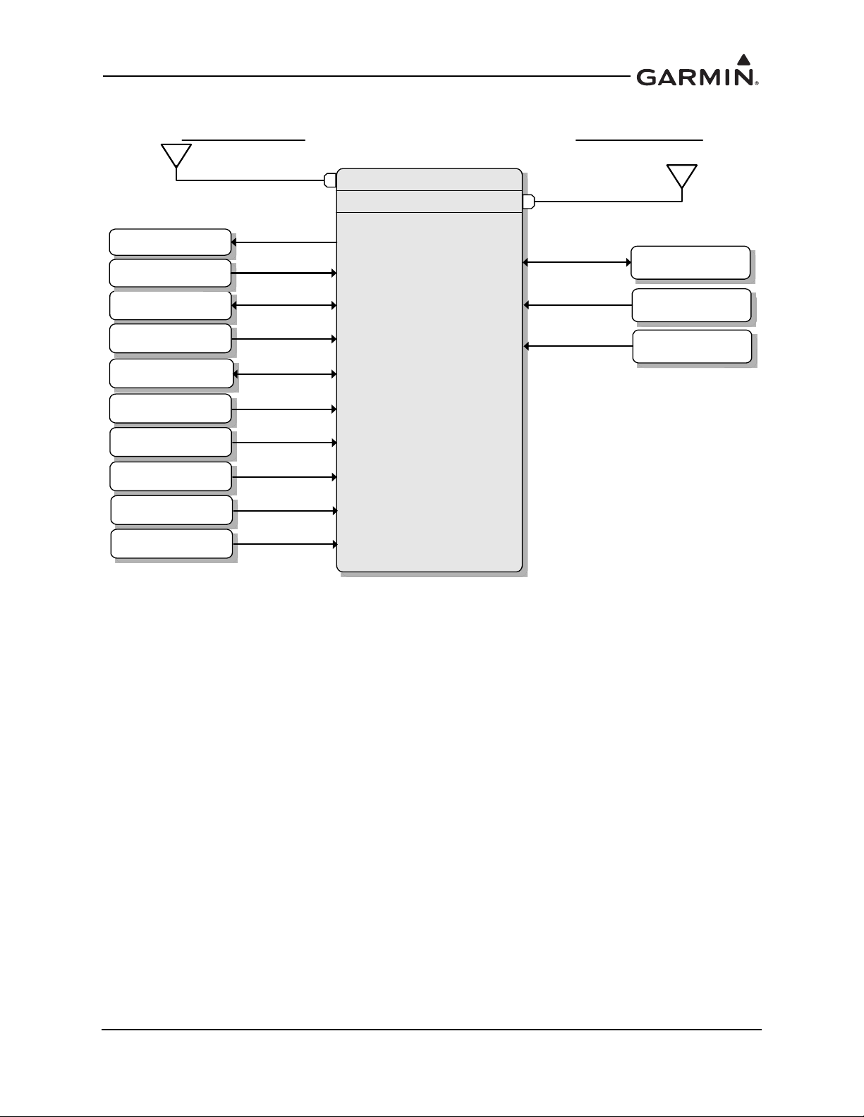
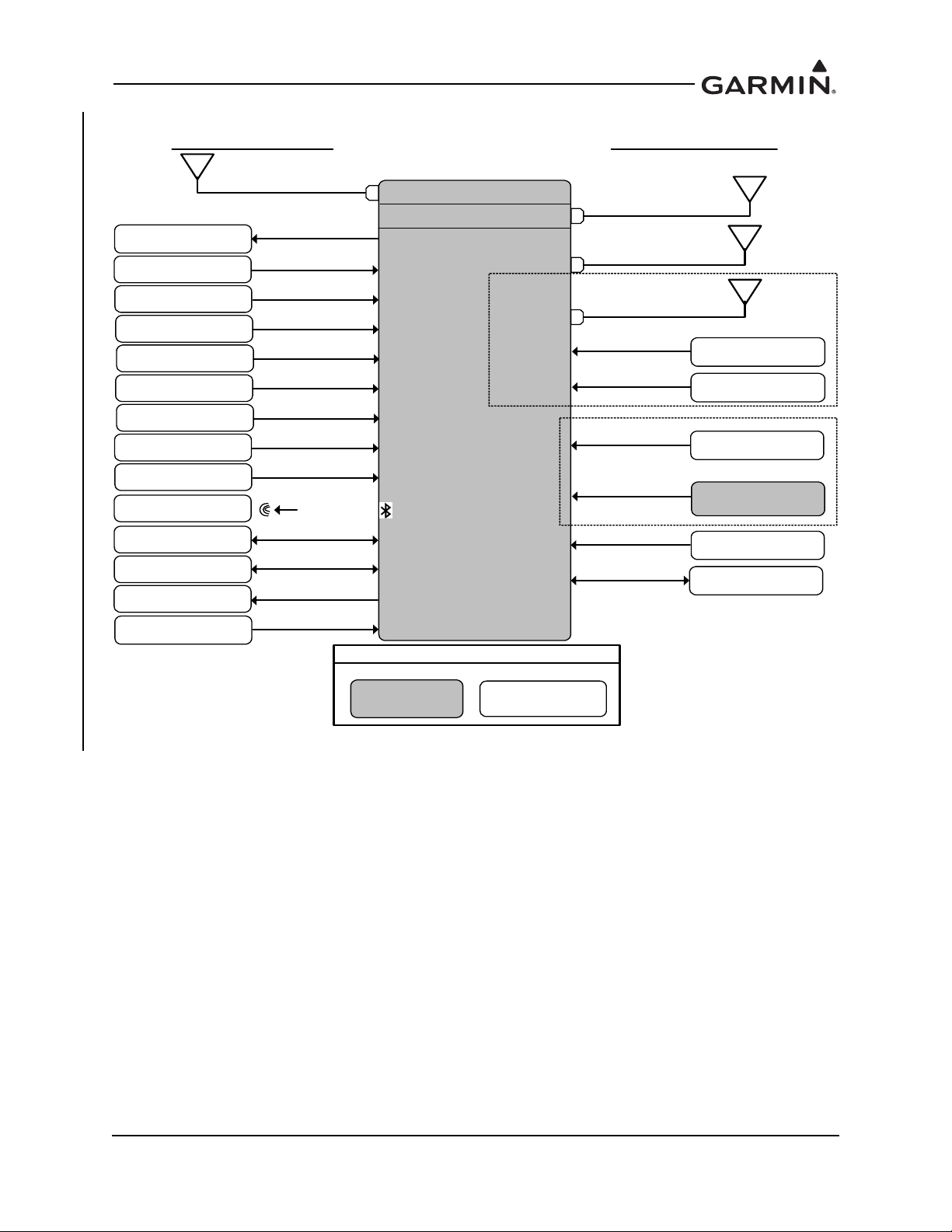
Figure 2-1 provides a summary of the interfaces provided for the GTX 330 or GTX 330D. Refer to
GTX 3XX Part 23 AML STC Installation Manual for interfaces allowed under this STC.
190-00734-11 GTX 33X and GTX 3X5 ADS-B Maintenance Manual
Rev. 6 Page 2-3
Figure 2-1 GTX 330 or GTX 330D Interface Summary
GTX 330
or
GTX 330D
Bottom Antenna
GTX 330D
Installs Only
Traffic System
Audio Panel
Optional Interfaces
Heading Source
Secondary GPS
Display
Required Interfaces
Altitude Source
Power/Ground
Top Antenna
GPS
Temperature
Squat Switch
External STBY
External Ident
Radar Altitude

190-00734-11 GTX 33X and GTX 3X5 ADS-B Maintenance Manual
Rev. 6 Page 2-4
2.2 GTX 33/33D
GTX 33/33D units are remote mounted and require a display/control interface as provided by the
GTN 6XX/7XX or GNS 480 in order to be installed in accordance with this STC. Basic transponder
functions of the GTX 33/33D are identical to the GTX 330/330D.
GTX 33/33D units provide the following features.
Mode S transponder
ADS-B Out capability
Entry and display of squawk code and flight ID*
Display of pressure altitude*
Display of density altitude*
Display of outside air temp*
Display of flight timers*
Audio output
TIS-A traffic output to a compatible display
*Requires supported external control and display system
The transponder annunciates when the unit has an ADS-B Out failure to alert the crew that the unit has a
degraded ADS-B system.
GTX 33/33D units communicate through the following interfaces.
ARINC 429
RS-232
Gray code
Discrete I/O
Power is provided by the aircraft’s existing avionics bus. Non-diversity GTX 33 units interface with a
transponder antenna mounted to the bottom of the fuselage. GTX 33D units interface to a transponder
antenna mounted to the top of the fuselage as well as an antenna mounted to the bottom.
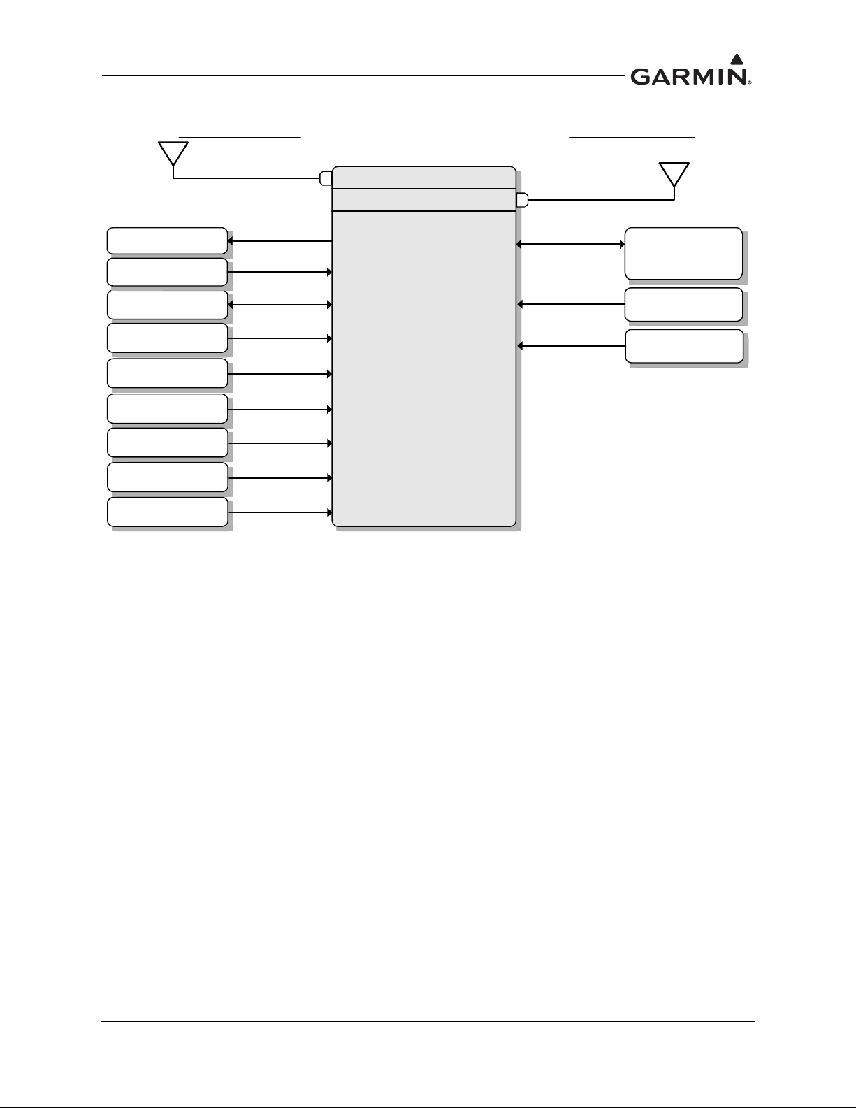
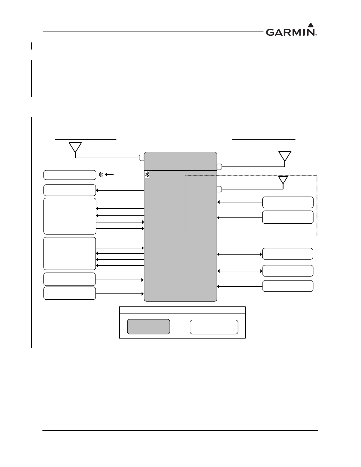
Figure 2-2 provides a summary of the interfaces provided for the GTX 33 or GTX 33D. Refer to
GTX 3XX Part 23 AML STC Installation Manual for interfaces allowed under this STC.
190-00734-11 GTX 33X and GTX 3X5 ADS-B Maintenance Manual
Rev. 6 Page 2-5
Figure 2-2 GTX 33 or GTX 33D Interface Summary
GTX 33
or
GTX 33D
Bottom Antenna
GTX 33D
Installs Only
Garmin
GTN 6XX/7XX
Or
GNS 480
Traffic System
Audio Panel
Optional Interfaces
Heading Source
Secondary GPS
Temperature
Squat Switch
Required Interfaces
Altitude Source
Power/Ground
Top Antenna
External Ident
External Standby
Radar Altitude

190-00734-11 GTX 33X and GTX 3X5 ADS-B Maintenance Manual
Rev. 6 Page 2-6
2.3 GTX 335/335D/335R/335DR
The GTX 335/335D/335R/335DR units are panel or remote mounted units providing Mode S with ADS-B
Out extended squitter capability. The panel mounted unit contains an integrated display while the remote
mounted unit requires an interface to a control source for normal operation and functionality.
GTX 335/335D/335R/335DR units provide the following features:
Mode S transponder
ADS-B Out capability
Optional internal GNSS receiver
Optional altitude encoder module
Entry and display of squawk code and flight ID
Display of pressure altitude
Display of outside air temp
Display of density altitude
Display of flight timers
Audio output
TIS-A traffic output to a compatible display
The transponder annunciates when the unit has an ADS-B Out failure to alert the crew that the unit has a
degraded ADS-B system. GTX 335/335R units interface with a transponder antenna mounted to the
bottom of the fuselage. GTX 335D/335DR units interface to a transponder antenna mounted to the top of
the fuselage as well as an antenna mounted to the bottom.
GTX 335/335D/335R/335DR units communicate through the following interfaces:
ARINC 429
RS-232
Gray code
Discrete I/O
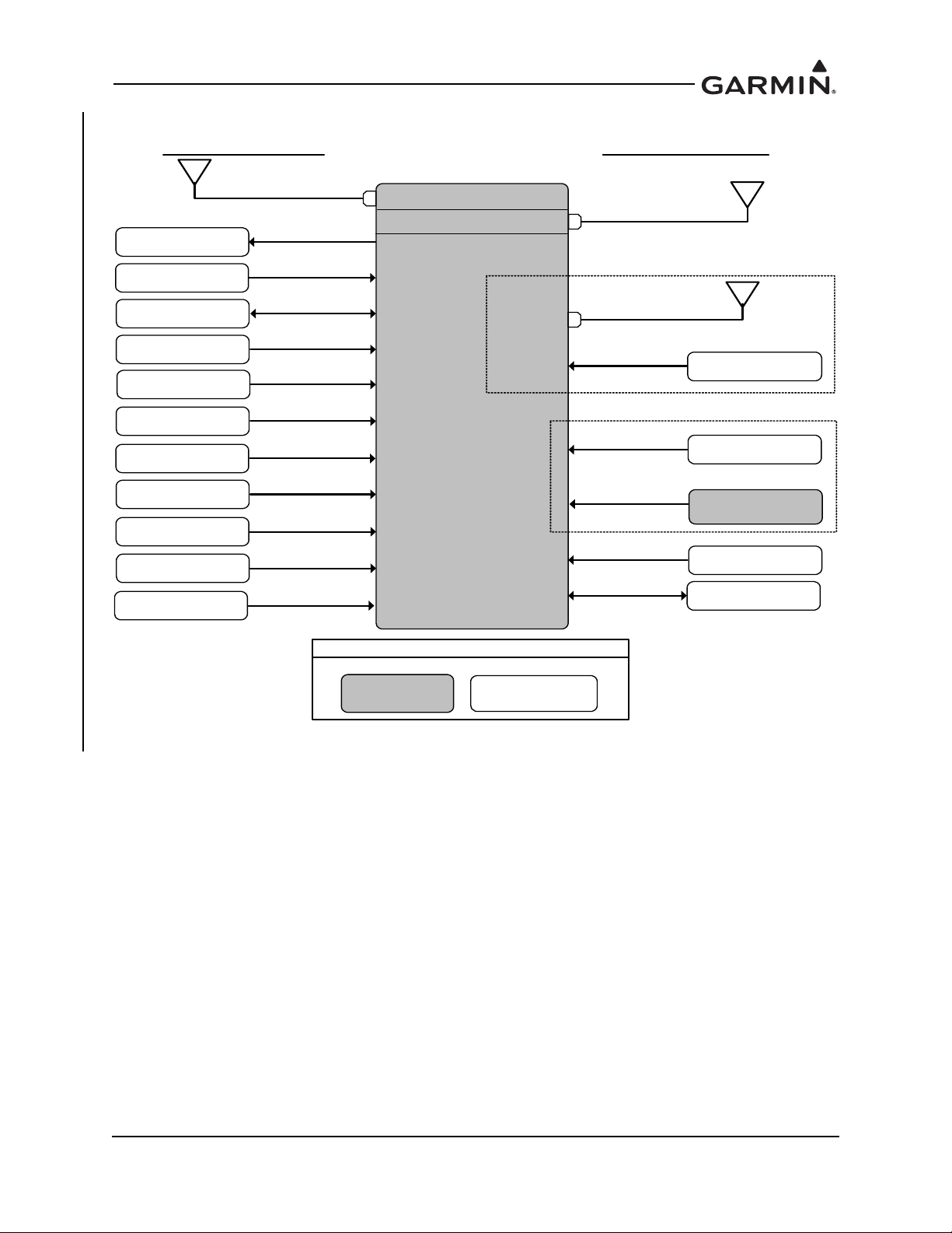
Figure 2-3 provides a summary of the interfaces provided for the GTX 335/335D/335R/335DR. Refer to
GTX 3XX Part 23 AML STC Installation Manual for interfaces allowed under this STC.
190-00734-11 GTX 33X and GTX 3X5 ADS-B Maintenance Manual
Rev. 6 Page 2-7
Figure 2-3 GTX 335/335D/335R/335DR Interface Summary
GTX 335/335R/
335D/335DR
GPS Antenna
GPS Source
Audio Panel
GTX 3X5 with GPS only
GTX 335R/335DR
Control
Power/Ground
Altitude Source
Heading Source
Air Data Source
Secondary GPS
Radio Altitude
Source
Existing LRUNew LRU
Legend
Optional Interfaces
Required Interfaces
Squat Sw itch
Garmin Altitude
Encoder
OR
Temperature
External Ident
External Standby
Traffic System
For XPDR Cross-Talk
Keep Alive Input
Bottom Antenna
GTX 335D/335DR
Installs O nly
Top Antenna

190-00734-11 GTX 33X and GTX 3X5 ADS-B Maintenance Manual
Rev. 6 Page 2-8
2.4 GTX 345/345D/345R/345DR
The GTX 345/345D/345R/345DR units are panel or remote mounted units providing Mode S with ADS-B
Out extended squitter, and UAT and 1090 receivers for ADS-B In capabilities. The panel mounted unit
contains an integrated display while the remote mounted units require an interface to a control source for
normal operation and functionality.
GTX 345/345D/345R/345DR units provide the following features:
Mode S transponder
ADS-B Out capability
ADS-B In capability with built-in 1090 MHz and UAT receivers
Optional internal GNSS receiver
Optional altitude encoder module
Entry and display of squawk code and flight ID
Display of pressure altitude
Display of outside air temp
Display of density altitude
Display of flight timers
Audio output
Bluetooth interface for display of weather and traffic on portable devices
The transponder annunciates when the unit has an ADS-B failure to alert the crew that the unit has a
degraded ADS-B In or ADS-B Out system. GTX 345/345R units interface with a transponder antenna
mounted to the bottom of the fuselage. GTX 345D/345DR units interface to a transponder antenna
mounted to the top of the fuselage as well as an antenna mounted to the bottom.
GTX 345/345D/345R/345DR units communicate through the following interfaces:
HSDB
ARINC 429
RS-232
RS-422
Gray code
Discrete I/O
Figure 2-4 provides a summary of the interfaces provided for the GTX 345/345D/345R/345DR. Refer to
GTX 3XX Part 23 AML STC Installation Manual for interfaces allowed under this STC.
190-00734-11 GTX 33X and GTX 3X5 ADS-B Maintenance Manual
Rev. 6 Page 2-9
Figure 2-4 GTX 345/345D/345R/345DR Interface Summary
TAS/TCAS I
Traffic Sensor
ADS-B Traffic
FIS-B Display
Bluetooth Device
GTX 345/345R/
345D/345DR
GPS Antenna
GPS Source
Audio Panel
Bottom Antenna
GTX 3X5 with GPS only
GTX 345R/345DR
Control
Power/Ground
Altitude Source
Heading Source
Air D ata S ource
Secondary GPS
Radio Altitude
Source
Existing LRUNew LRU
Legend
Optional Interfaces
Required Interfaces
Squat Switch
Bluetooth
External Traffic
Annunciator
For N o Display Install
Garmin Altitude
Encoder
OR
Temperature
External Ident
External Standby
Keep Alive Input
Bottom Antenna
GTX 345D/345DR
Installs O nly
Top Antenna
Time Mark
GTX 345D/345DR
only
190-00734-11 GTX 33X and GTX 3X5 ADS-B Maintenance Manual
Rev. 6 Page 2-10
2.5 GTX 335R/335DR/345R/345DR with Legacy G1000
The Legacy G1000 configuration includes certain G1000 systems that can be updated with a G1000
interface card. The GTX 335R/335DR provides all the functions listed under the GTX 335/335D/335R/
335DR to include ADS-B Out. The GTX 345R provides all the functions listed under the GTX 345/345D/
345R/345DR with the exception that the ADS-B In traffic and weather will be displayed as an emulation of
the GDL 90 weather and traffic displays. The GTX 345R/345DR provides FIS-B weather (NEXRAD and
METARS) and TIS-B traffic within the confines of the GDL 90 interface. The GTX 345R/345DR provides
TIS-B traffic and FIS-B weather on PED via Bluetooth. Refer to GTX 3XX Part 23 AML STC Installation
Manual for additional information.
Figure 2-5 provides a basic summary of the GTX 335R/335DR/345R/345DR interface for the legacy
G1000 system.
Figure 2-5 GTX 335R/335DR/345R/345DR Interface Summary with Legacy G1000
Bluetooth Device
GTX 335R/335DR/
345R/345DR
GPS Antenna
Audio Panel
GTX 3X5 with GPS only
Power/Ground
GIA #1
Existing LRU
New LRU
Legend
Optional Interfaces
Required Interfaces
Bluetooth
RS-232
RS-232
GIA #2
RS-232
RS-422
TRAFFIC
WEATHER
ARINC 429
TRUE HEADING
GIA #2
GIA 63W
GPS Source
GIA 63W software dependent,
refer to IM for compatible software
TAS/TCAS
AURAL MUTE
DISCRETE
ARINC 429
DISCRETE
ARINC 429
TRAFFIC
XPDR / HEADING
DISCRETE
STBY/OPR
SELF TEST
Landing Gear
Switch
DISCRETE
Keep Alive Input
Bottom Antenna
GTX 335DR/345DR
Installs Only
Top Antenna
Time Mark
GTX 345DR only
190-00734-11 GTX 33X and GTX 3X5 ADS-B Maintenance Manual
Rev. 6 Page 2-11
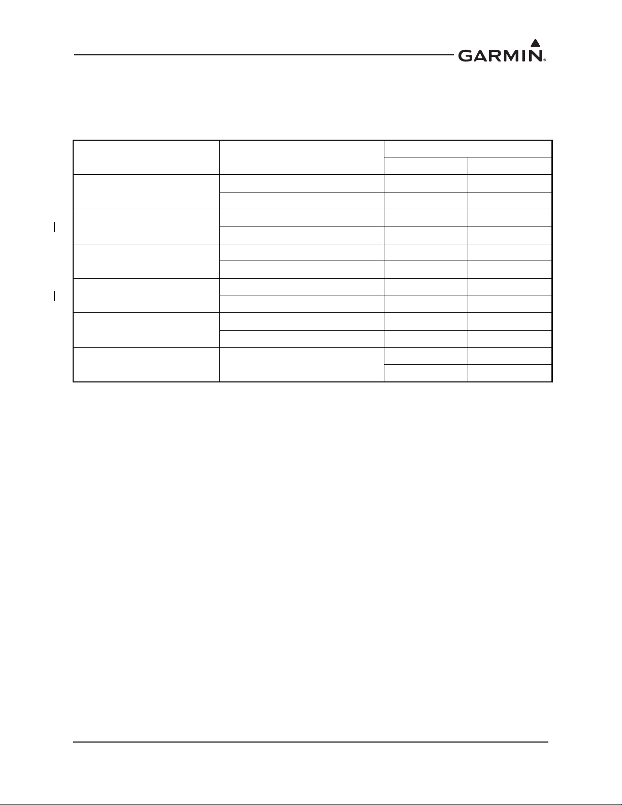
2.6 Electrical Load Information
Electrical load information for the GTX is provided below. Appendix A of this document contains details
specific to the load changes for the installation.
Table 2-1 GTX Electrical Load
Unit Characteristic
Specification
14 VDC 28 VDC
GTX 33/330
Maximum full TSO reply rate 3.1 A 1.6 A
Maximum quiescent 1.1 A 0.85 A
GTX 335/335D
Input current, typical 0.57 A 0.29 A
Input current, maximum 0.86 A 0.43 A
GTX 335, GPS
Input current, typical 0.72 A 0.36A
Input current, maximum 1.22 A 0.61 A
GTX 345/345D
Input current, typical 0.72 A 0.36 A
Input current, maximum 1.30 A 0.65 A
GTX 345, GPS
Input current, typical 1.07 A 0.54 A
Input current, maximum 1.43 A 0.72 A
GTX 335/345, GPS Input current, GPS KEEP ALIVE
65 µA typical 20 µA typical
85 µA maximum 40 µA maximum

190-00734-11 GTX 33X and GTX 3X5 ADS-B Maintenance Manual
Rev. 7 Page 3-1
3 GTX CONTROL AND OPERATION
3.1 GTX 330/330D .................................................................................................................................3-2
3.2 GTX 335/335D/345/345D ................................................................................................................3-4
3.3 GTX 33/33D and GTX 335R/335DR/345R/345DR ........................................................................3-7
3.4 GTX 335R/335DR/345R/345DR with Legacy G1000.....................................................................3-8
3.5 GTX 3X5 Install Tool.....................................................................................................................3-10
3.5.1 State Page .................................................................................................................................3-11
3.5.2 Status Page ...............................................................................................................................3-12
3.5.3 Configuration Group ................................................................................................................3-13
3.5.4 Diagnostics Group ....................................................................................................................3-14
3.5.5 Product Data Group..................................................................................................................3-15
3.5.6 Software Upload.......................................................................................................................3-15
Control and operation of GTX 330/330D and GTX 335/335D/345/345D units occur through the front
panel of the GTX. Control and operation of the remote mounted GTX 33/33D and GTX 335R/335DR/
345R/345DR is handled through the external interface provided via the GTN 6XX/7XX or GNS 480.
ADS-B In information from the GTX 345 can be displayed through the external interface provided via the
GTN 6XX/7XX or GNS 400W/500W Series. Figure 3-3 and Figure 3-4 show display units control of the
transponder. Figure 3-5 shows transponder control using the GNS 480.
In specific installations, the GDU 1XXX (of the G1000 system) provides control and operation of the
remote mounted GTX 335R/335DR/345R/345DR units. Section 3.4 describes the functions of the G1000
system.
NOTE
The selected identification code should be entered carefully, either one assigned by air
traffic control for IFR flight or an applicable VFR transponder code.
Important Codes
1200 VFR code for any altitude in the US (refer to ICAO standards)
7000 VFR code commonly used in Europe (refer to ICAO standards)
7500 Hijack code (aircraft is subject to unlawful interference)
7600 Loss of communications
7700 Emergency
Avoid selecting code 7500 and all codes in the 7600-7777 range. These codes trigger special emergency
alerts in ATC monitoring facilities. An aircraft’s transponder code is used for ATC tracking purposes,
therefore be careful when making routine code changes.
190-00734-11 GTX 33X and GTX 3X5 ADS-B Maintenance Manual
Rev. 7 Page 3-2
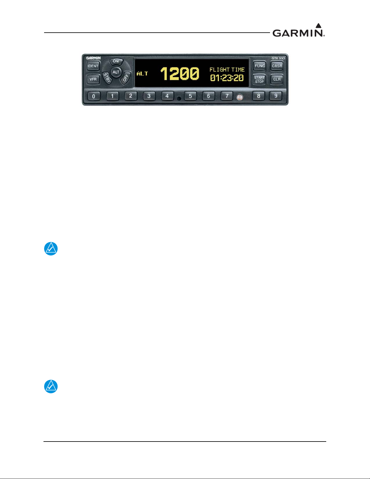
3.1 GTX 330/330D
Figure 3-1 GTX 330/330D Front Panel
Function Selection Keys
The function selection keys are:
OFF Powers off the GTX 330.
STBY Selects the standby mode. Pressing the STBY key when the GTX 330 is powered off
automatically powers the unit on in standby mode. When in standby mode, the transponder
does not reply to interrogations. If using software v8.02 or later, GND mode is
automatically determined using either a squat switch or calculated data from various system
inputs including GPS data from an approved control/display unit such as a GTN 6XX/7XX,
GNS 400W/500W Series, or GNS 480.
ON Selects Mode A and Mode S. Pressing the ON key when the GTX 330 is powered off
automatically powers on the unit in Mode A and will transmit a squawk code when
interrogated.The transponder replies to Mode A and Mode S interrogations, as indicated by
the reply symbol (®). The replies do not include altitude information.
NOTE
If the transponder is in the ON or ALT operating mode, the transponder becomes an active
part of the Air Traffic Control Radar Beacon System (ATCRBS). The transponder
responds to interrogations from TCAS equipped aircraft.
ALT Selects Mode A, Mode C, and Mode S. Pressing the ALT key when the GTX 330 is
powered off automatically powers on the unit in altitude reporting mode.The transponder
replies to identification, altitude and Mode S interrogations as indicated by the reply symbol
(®). Replies to altitude interrogations include the standard pressure altitude received from
an external altitude source, which is not adjusted for barometric pressure.
IDENT Pressing the IDENT key activates the Special Position Identification (SPI) Pulse for 18
seconds, identifying the transponder return from others on an air traffic controller’s screen.
During the IDENT period, the word “IDENT” appears in the upper left corner of the display.
VFR Sets the transponder code to the pre-programmed VFR code selected in Configuration mode
(Set to 1200 at the factory). Pressing the VFR key again restores the previous identification
code.
NOTE
The VFR key is on (functional) by default, but can be disabled in configuration mode.
FUNC Changes the page shown on the right side of the display. Display data includes pressure
altitude, flight time, altitude monitor, count up, and count down timers. In the
Configuration mode, steps through the function pages.

190-00734-11 GTX 33X and GTX 3X5 ADS-B Maintenance Manual
Rev. 7 Page 3-3
START/STOP Starts and stops the altitude monitor, count up, count down, and flight timers.
CRSR Initiates entry of the starting time for the count down timer and cancels transponder code
entry. Selects changeable fields in Configuration mode. If using software v8.02 or later,
holding the CRSR key during power on will place the unit into a Ground Test mode that
forces the aircraft into an airborne status for testing purposes.
CLR Resets the count up, count down, and flight timers. Cancels the previous key press during
code selection and count down entry. Used in Configuration mode.
8 Reduces contrast and display brightness when the respective fields are displayed and
enters the number eight into the count down timer. Used in Configuration mode.
9 Increases contrast and display brightness when the respective fields are displayed and
enters the number nine into the count down timer. Used in Configuration mode.
Code Selection
Code selection is entered with eight keys (0 – 7) providing 4,096 active identification codes. Pushing one
of these keys begins the code selection sequence. The new code is not activated until the fourth digit is
entered. Pressing the CLR key moves the cursor back to the previous digit. Pressing the CLR key when
the cursor is on the first digit of the code, or pressing the CRSR key during code entry, removes the cursor
and cancels data entry, restoring the previous code. You may press the CLR key up to five seconds after
code entry is complete to return the cursor to the fourth digit. The numbers 8 and 9 are not used for code
entry, only for entering a count down time, contrast and display brightness, and data selection in the
Configuration mode.
Function Display
PRESSURE ALT Displays the altitude data supplied to the GTX 330 in feet, hundreds of
feet (flight level), or meters, depending on configuration.
FLIGHT TIME Displays the flight time, controlled by the START/STOP key or by one
of four airborne sources (squat switch, GPS ground speed recognition, air
data airspeed recognition, or altitude increase) as configured during
installation. The timer begins when the GTX 330 determines that the
aircraft is airborne.
ALT MONITOR Controlled by START/STOP key. Activates a voice alarm and warning
annunciator when altitude limit is exceeded.
OAT/DALT Displayed when the GTX 330 is configured with temperature input.
Displays outside air temperature and density altitude.
COUNT UP Timer controlled by START/STOP and
CLR keys.
COUNT DOWN Timer controlled by START/STOP, CLR, and CRSR keys. The initial
count down time is entered with the 0 – 9 keys.
CONTRAST This page is only displayed if manual contrast mode is selected in
Configuration mode. Contrast is controlled by the 8 and 9 keys.
DISPLAY This page is only displayed if manual backlighting mode is selected in
Configuration mode. Backlighting is controlled by the 8 and 9 keys.
ADS-B TX Controlled by START/STOP key. Starts/stops extended squitter
function.
FLIGHT ID If the GTX 33X is using software v8.02 or later and the system is
configured to allow the pilot to edit the flight ID, then the flight ID may
be entered using the CRSR key. Otherwise the flight ID is set in
configuration mode and cannot be changed during normal operation.

190-00734-11 GTX 33X and GTX 3X5 ADS-B Maintenance Manual
Rev. 7 Page 3-4
3.2 GTX 335/335D/345/345D
Figure 3-2 GTX 335/335D/345/345D Front Panel
Function Selection Keys
The function selection keys are:
OFF Powers off the GTX 3X5.
STBY Selects the Standby mode. Pressing the STBY key when the GTX 3X5 is powered off
automatically powers the unit on in standby mode. When in Standby mode, the transponder
does not reply to interrogations but new codes can be entered and a SBY indication appears
on the display.
ON Selects the On mode, which generates Mode A and Mode S replies, but Mode C altitude
reporting is inhibited. Pressing the ON key when the GTX 3X5 is powered off automatically
powers on the unit in Mode A and will transmit a squawk code when interrogated. ADS-B
Out will not return barometric altitude as it switches to GPS altitude in this mode.
Interrogations are indicated by the reply symbol (®). The replies do not include altitude
information.
NOTE
If the transponder is in the ON or ALT operating mode, the transponder becomes an active
part of the Air Traffic Control Radar Beacon System (ATCRBS). The transponder
responds to interrogations from TCAS equipped aircraft.
ALT Altitude mode is automatically selected when the aircraft becomes airborne using the unit’s
air/ground logic or when the ALT key is pressed. Pressing the ALT key when the
GTX 3X5 is powered off automatically powers on the unit in altitude reporting mode. While
the aircraft is on the ground and in ALT mode, the transponder does not allow Mode A and
Mode C replies, but it does permit acquisition squitter and replies to Mode S interrogations.
While the aircraft is in ALT mode and airborne, it will generate Mode A, Mode C and Mode
S replies as well as transmit acquisition and extended squitter, including ADS-B Out.
All transponder interrogations are indicated by the reply symbol (®).
IDENT Pressing the IDENT key activates the Special Position Identification (SPI) Pulse for 18
seconds, identifying the transponder return from others on an air traffic controller’s screen.
During the IDENT period, the word “IDENT” appears in the upper left corner of the display.
VFR Sets the transponder code to the pre-programmed VFR code selected in Configuration mode
(Set to 1200 at the factory). Pressing the VFR key again restores the previous identification
code.

190-00734-11 GTX 33X and GTX 3X5 ADS-B Maintenance Manual
Rev. 7 Page 3-5
FUNC In normal mode, pressing the FUNC key changes the subpage group shown on the right side
of the display. Subpages include flight ID, pressure altitude, flight time, altitude monitor,
system count up, and count down timers. In the Configuration mode, steps through the
function pages.
ENT Confirms entry for selected item and moves the cursor to the next editable item, or function
selection, in configuration and normal operation. Starts and stops the altitude monitor, count
up, count down, and flight timers.
CRSR Selects changeable fields in configuration and normal operation. Initiates entry of the
starting time for the count down timer and cancels transponder code entry. Holding the
CRSR key during power on will place the unit into a Ground Test mode that forces the
aircraft into an airborne status for testing purposes.
CLR Resets the count up, count down and flight timers. Cancels the previous key press during
code selection, count down entry, or flight ID entry. Used in Configuration mode to scroll
through the function pages.
8 Used as a scroll-up key to navigate through page groups in normal and configuration mode.
9 Used as a scroll-down key to navigate through page groups in normal and configuration
mode.
Code Selection
Code selection is entered with eight keys (0 – 7) providing 4,096 active identification codes. Pushing one
of these keys begins the code selection sequence. The new code is not activated until the fourth digit is
entered. Pressing the CLR key moves the cursor back to the previous digit. Pressing the CLR key when
the cursor is on the first digit of the code, or pressing the CRSR key during code entry, removes the cursor
and cancels data entry, restoring the previous code. The numbers 8 and 9 are not used for code entry, only
for flight ID entry, count down time, aircraft tail number entry, and data selection in Configuration and
Normal mode.
Configuration Mode
To enter configuration mode, press and hold the ENT key, then energize the unit. To exit configuration
mode, press and hold the OFF key until the unit de-energizes.
To cycle through the pages, press the FUNC key
To access items on the page, press the CRSR key
To cycle through the selections of an item on the page, press the 8 or 9 key
To scroll up or down on the page when nothing is selected, press the 8 or 9 key
To move within the page, press the ENT key
To move to previous selection on the page, press the CLR key
To exit the page, press the FUNC key
GTX 3X5 units may also be configured using the GTX 3X5 Install Tool. For configuration using the
GTX 3X5 Install Tool, refer to Section 3.5.
Loading...