


Kodiak 100
Table of contents
 Loading...
Integrated Flight Deck
Cockpit Reference Guide
Quest
Kodiak 100


Garmin G1000 Cockpit Reference Guide for the Quest Kodiak 100
Copyright © 2007 Garmin Ltd. or its subsidiaries. All rights reserved.
This manual reflects the operation of System Software version 0552.00 or later for the Quest Kodiak 100. Some differences in
operation may be observed when comparing the information in this manual to earlier or later software versions.
Garmin International, Inc., 1200 East 151st Street, Olathe, Kansas 66062, U.S.A.
Tel: 913/397.8200 Fax: 913/397.8282
Garmin AT, Inc., 2345 Turner Road SE, Salem, OR 97302, U.S.A.
Tel: 503/391.3411 Fax 503/364.2138
Garmin (Europe) Ltd., Unit 5, The Quadrangle, Abbey Park Industrial Estate, Romsey, Hampshire S051 9DL, U.K.
Tel: 44/0870.851241 Fax: 44/0870.8501251
Garmin Corporation, No. 68, Jangshu 2nd Road, Shijr, Taipei County, Taiwan
Tel: 886/02.2642.9199 Fax: 886/02.2642.9099
Web Site Address: www.garmin.com
Except as expressly provided herein, no part of this manual may be reproduced, copied, transmitted, disseminated, downloaded or
stored in any storage medium, for any purpose without the express written permission of Garmin. Garmin hereby grants permission
to download a single copy of this manual and of any revision to this manual onto a hard drive or other electronic storage medium to
be viewed for personal use, provided that such electronic or printed copy of this manual or revision must contain the complete text
of this copyright notice and provided further that any unauthorized commercial distribution of this manual or any revision hereto is
strictly prohibited.
Garmin
®
and G1000
®
are registered trademarks of Garmin Ltd. or its subsidiaries. These trademarks may not be used without the
express permission of Garmin.
NavData
®
is a registered trademark of Jeppesen, Inc.; Stormscope
®
is a registered trademark of L-3 Communications; and XM
®
is a
registered trademark of XM Satellite Radio, Inc.
March 2007 190-00645-00 Rev. A Printed in the U.S.A.

190-00645-00 Rev. A
Garmin G1000 Cockpit Reference Guide for the Quest Kodiak 100
WARNINGS,
CAUTIONS, & NOTES
WARNING: Navigation and terrain separation must NOT be predicated upon the use of the terrain function.
The G1000 Terrain Proximity feature is NOT intended to be used as a primary reference for terrain avoidance
and does not relieve the pilot from the responsibility of being aware of surroundings during flight. The Terrain
Proximity feature is only to be used as an aid for terrain avoidance and is not certified for use in applications
requiring a certified terrain awareness system. Terrain data is obtained from third party sources. Garmin is
not able to independently verify the accuracy of the terrain data.
WARNING: The displayed minimum safe altitudes (MSAs) are only advisory in nature and should not be relied
upon as the sole source of obstacle and terrain avoidance information. Always refer to current aeronautical
charts for appropriate minimum clearance altitudes.
WARNING: The altitude calculated by G1000 GPS receivers is geometric height above Mean Sea Level and could
vary significantly from the altitude displayed by pressure altimeters, such as the GDC 74A Air Data Computer,
or other altimeters in aircraft. GPS altitude should never be used for vertical navigation. Always use pressure
altitude displayed by the G1000 PFD or other pressure altimeters in aircraft.
WARNING: Do not use outdated database information. Databases used in the G1000 system must be updated
regularly in order to ensure that the information remains current. Pilots using any outdated database do so
entirely at their own risk.
WARNING: Do not use basemap (land and water data) information for primary navigation. Basemap data is
intended only to supplement other approved navigation data sources and should be considered as an aid to
enhance situational awareness.
WARNING: Traffic information shown on the G1000 Multi Function Display is provided as an aid in visually
acquiring traffic. Pilots must maneuver the aircraft based only upon ATC guidance or positive visual acquisition
of conflicting traffic.
WARNING: Use of the Stormscope is not intended for hazardous weather penetration (thunderstorm penetration).
Stormscope information, as displayed on the G1000 MFD, is to be used only for weather avoidance, not
penetration.
WARNING: GDL 69 Weather should not be used for hazardous weather penetration. Weather information
provided by the GDL 69 is approved only for weather avoidance, not penetration.

190-00645-00 Rev. A
Garmin G1000 Cockpit Reference Guide for the Quest Kodiak 100
WARNINGS,
CAUTIONS, & NOTES
WARNING: NEXRAD weather data is to be used for long-range planning purposes only. Due to inherent delays
in data transmission and the relative age of the data, NEXRAD weather data should not be used for short-range
weather avoidance.
WARNING: The Garmin G1000, as installed in the Quest Kodiak 100 aircraft, has a very high degree of
functional integrity. However, the pilot must recognize that providing monitoring and/or self-test capability for
all conceivable system failures is not practical. Although unlikely, it may be possible for erroneous operation to
occur without a fault indication shown by the G1000. It is thus the responsibility of the pilot to detect such an
occurrence by means of cross-checking with all redundant or correlated information available in the cockpit.
WARNING: For safety reasons, G1000 operational procedures must be learned on the ground.
WARNING: The United States government operates the Global Positioning System and is solely responsible
for its accuracy and maintenance. The GPS system is subject to changes which could affect the accuracy
and performance of all GPS equipment. Portions of the Garmin G1000 utilize GPS as a precision electronic
NAVigation AID (NAVAID). Therefore, as with all NAVAIDs, information presented by the G1000 can be misused
or misinterpreted and, therefore, become unsafe.
WARNING: To reduce the risk of unsafe operation, carefully review and understand all aspects of the G1000
Pilot’s Guide documentation and the Quest Kodiak 100 Pilot’s Operating Handbook. Thoroughly practice basic
operation prior to actual use. During flight operations, carefully compare indications from the G1000 to all
available navigation sources, including the information from other NAVAIDs, visual sightings, charts, etc. For
safety purposes, always resolve any discrepancies before continuing navigation.
WARNING: The illustrations in this guide are only examples. Never use the G1000 to attempt to penetrate a
thunderstorm. Both the FAA Advisory Circular, Subject: Thunderstorms, and the Airman’s Information Manual
(AIM) recommend avoiding “by at least 20 miles any thunderstorm identified as severe or giving an intense
radar echo.”
CAUTION: The GDU 1040 PFD and MFD displays use a lens coated with a special anti-reflective coating that is
very sensitive to skin oils, waxes, and abrasive cleaners. CLEANERS CONTAINING AMMONIA WILL HARM THE
ANTI-REFLECTIVE COATING. It is very important to clean the lens using a clean, lint-free cloth and an eyeglass
lens cleaner that is specified as safe for anti-reflective coatings.
190-00645-00 Rev. A
Garmin G1000 Cockpit Reference Guide for the Quest Kodiak 100
WARNINGS,
CAUTIONS, & NOTES
CAUTION: The Garmin G1000 does not contain any user-serviceable parts. Repairs should only be made by
an authorized Garmin service center. Unauthorized repairs or modifications could void both the warranty and
the pilot’s authority to operate this device under FAA/FCC regulations.
NOTE: When using Stormscope, there are several atmospheric phenomena in addition to nearby thunderstorms
that can cause isolated discharge points in the strike display mode. However, clusters of two or more discharge
points in the strike display mode do indicate thunderstorm activity if these points reappear after the screen has
been cleared.
NOTE: All visual depictions contained within this document, including screen images of the G1000 panel and
displays, are subject to change and may not reflect the most current G1000 system. Depictions of equipment
may differ slightly from the actual equipment.
NOTE: This device complies with part 15 of the FCC Rules. Operation is subject to the following two conditions:
(1) this device may not cause harmful interference, and (2) this device must accept any interference received,
including interference that may cause undesired operation.
NOTE: This product, its packaging, and its components contain chemicals known to the State of California to
cause cancer, birth defects, or reproductive harm. This notice is being provided in accordance with California’s
Proposition 65. If you have any questions or would like additional information, please refer to our web site at
www.garmin.com/prop65.
190-00645-00 Rev. A
Garmin G1000 Cockpit Reference Guide for the Quest Kodiak 100
RR-1
RECORD OF REVISIONS
Part Number Change Summary
190-00645-00 Initial release.
Revision Date of Revision Affected Pages Description
A March, 2007 i through Index-4 Production release

190-00645-00 Rev. A
Garmin G1000 Cockpit Reference Guide for the Quest Kodiak 100
RR-2
RECORD OF REVISIONS
Blank Page

190-00645-00 Rev. A
Garmin G1000 Cockpit Reference Guide for the Quest Kodiak 100
i
TABLE OF CONTENTS
SECTION 1: SYSTEM OVERVIEW .................................... 1-1
1.1 PFD/MFD Controls ................................................... 1-2
1.2 PFD Softkeys ............................................................ 1-4
1.3 MFD Softkeys ..........................................................1-7
1.4 MFD Page Groups ................................................... 1-8
1.5 Backlighting ............................................................. 1-8
1.6 Database Updates .................................................. 1-9
Aviation Database Update ........................................... 1-9
Terrain and Obstacle Database Updates ....................... 1-9
SECTION 2: FLIGHT INSTRUMENTS .............................. 2-1
2.1 Airspeed Indicator .................................................. 2-3
Speed Indication .........................................................2-3
Speed Ranges ............................................................. 2-3
Airspeed Trend Vector ................................................. 2-3
Vspeed References ...................................................... 2-3
2.2 Attitude Indicator ..................................................2-3
2.3 Altimeter .................................................................. 2-4
Altitude Select Bug ...................................................... 2-4
Altitude Trend Vector ................................................... 2-4
Barometric Setting Box ................................................ 2-4
Altitude Alerting .......................................................... 2-4
Barometric Minimum Descent Altitude .........................2-4
2.4 Vertical Deviation/Glideslope Indicator ............ 2-5
2.5 Marker Beacon Annunciations ............................2-5
2.6 Vertical Speed Indicator ....................................... 2-5
2.7 Horizontal Situation Indicator (HSI) ...................2-6
Arc HSI .......................................................................2-6
Turn Rate Indicator and Heading Trend Vector .............. 2-6
Course Pointer ............................................................ 2-7
Course Deviation Indicator (CDI) ..................................2-7
Bearing Pointers and Information Windows .................. 2-7
Navigation Source ....................................................... 2-8
SECTION 3: ENGINE INDICATION .................................. 3-1
Engine Display ............................................................3-1
Engine System Display .................................................3-1
Engine Fuel Display ..................................................... 3-2
SECTION 4: NAV/COM AND TRANSPONDER .......... 4-1
4.1 NaV/coM Description ...............................................4-1
4.1 Radio Status Indications ....................................... 4-3
4.2 Volume ......................................................................4-3
4.3 Automatic Squelch ................................................. 4-3
4.4 Quickly Activating 121.500 MHz .......................... 4-3
4.5 Frequency Auto-tuning ......................................... 4-3
Auto-tuning on the PFD .............................................. 4-3
Auto-tuning on the MFD .............................................4-3
4.5 Transponder Operation ........................................... 4-4
Mode Selection ........................................................... 4-4
Reply Status ................................................................ 4-4
Code Selection ............................................................ 4-4
Flight ID Reporting ...................................................... 4-5
SECTION 5: AUDIO PANEL ................................................5-1
5.1 COM Radio Selection ............................................. 5-2
5.2 Marker Beacon Receiver ....................................... 5-2
Marker Beacon Signal Sensitivity .................................5-2
5.3 Nav Radio Audio Selection ................................... 5-2
5.4 Intercom System (ICS) Isolation .......................... 5-3
5.5 Intercom Squelch Control ..................................... 5-3
5.6 Digital Clearance Recorder and Player .............5-4
5.7 Reversionary Mode .................................................. 5-4
SECTION 6: AUTOMATIC FLIGHT CONTROL ............. 6-1
SECTION 7: NAVIGATION .................................................. 7-1
7.1 Navigation Map Page ............................................ 7-1
Select the MAP Page Group ......................................... 7-1
7.2 Direct-to Navigation ..............................................7-1
Direct-to Navigation from the MFD .............................. 7-1
Direct-to Navigation from the PFD ............................... 7-2
7.3 Airport Information ............................................... 7-3
Select the Airport Information Page ............................. 7-3
7.4 Intersection Information ...................................... 7-4
Select the Intersection Information Page ...................... 7-4
7.5 NDB Information ..................................................... 7-4
Select the NDB Information Page .................................7-4
7.6 VOR Information ..................................................... 7-5
Select the VOR Information Page .................................7-5
7.7 User Waypoint Information Page .......................7-5
7.8 Nearest Airports ..................................................... 7-5
Nearest Airport Information on the MFD ...................... 7-5
Nearest Airports Information on the PFD ...................... 7-6
7.9 Nearest Intersections ............................................ 7-7
Select the Nearest Intersections Page ........................... 7-7
7.10 Nearest NDB ............................................................7-7
Select the Nearest NDB Page ....................................... 7-7
7.11 Nearest VOR .............................................................7-8
Select the Nearest VOR Page ....................................... 7-8

190-00645-00 Rev. A
Garmin G1000 Cockpit Reference Guide for the Quest Kodiak 100
ii
TABLE OF CONTENTS
7.12 Nearest User Waypoint ..........................................7-8
Select the Nearest User Waypoint Page ........................ 7-8
7.13 Nearest Frequencies .............................................. 7-9
Select the Nearest Frequencies Page ............................ 7-9
7.14 Nearest Airspaces ................................................... 7-9
Select the Nearest Airspaces Page ................................ 7-9
SECTION 8: FLIGHT PLANNING ...................................... 8-1
8.1 User Defined Waypoints ........................................ 8-1
Select the User WPT Information Page ......................... 8-1
Create User Waypoints from the Navigation Map Page .8-2
8.2 Viewing the Active Flight Plan ............................ 8-2
8.3 Activate a Stored Flight Plan ............................... 8-2
8.4 Activate a Flight Plan Leg ....................................8-3
8.5 Stop Navigating a Flight Plan .............................. 8-3
8.6 Invert Active Flight Plan ....................................... 8-3
8.7 Create a New Flight Plan ...................................... 8-4
Create a New Flight Plan Using the MFD ..................... 8-4
Create a New Flight Plan Using the PFD ......................8-4
8.8 Load a Departure ...................................................8-5
8.9 Load an Arrival ........................................................ 8-5
8.10 Load an Approach ..................................................8-5
8.11 Remove a Departure, Arrival, or Approach
from a Flight Plan ...................................................8-5
8.12 Store a Newly Created Flight Plan ..................... 8-5
8.13 Edit a Stored Flight Plan ....................................... 8-5
8.14 Delete a Waypoint from the Flight Plan ............ 8-5
8.15 Invert and activate a Stored Flight Plan ...........8-6
8.16 Copy a Flight Plan ..................................................8-6
8.17 Delete a Flight Plan ............................................... 8-6
8.18 Graphical Flight Plan Creation ............................8-6
8.19 Trip Planning ............................................................8-6
8.20 Vertical Navigation (VNAV) Page ........................ 8-8
Create a Vertical Navigation Profile .............................. 8-8
VNAV Page Menu Options ...........................................8-9
SECTION 9: PROCEDURES ................................................9-1
9.1 Arrivals and Departures ........................................ 9-1
Load and Activate a Departure Procedure ....................9-1
Load and Activate An Arrival Procedure ........................ 9-1
9.2 Approaches .............................................................. 9-2
Load and/or Activate an Approach Procedure ............... 9-2
Activate An Approach in the Active Flight Plan ............. 9-3
SECTION 10: HAZARD AVOIDANCE ...........................10-1
10.1 Customizing the Hazard Displays on the
Navigation Map .................................................... 10-1
10.2 STORMSCOPE
®
(Optional) ................................... 10-1
Displaying Stormscope Lightning Data on the
Navigation Map Page ................................................ 10-1
Stormscope Page ....................................................... 10-2
10.3 XM Weather (Optional) ....................................... 10-3
Displaying METAR and TAF information on the
Airport Information Page ........................................... 10-3
Displaying Weather on the Weather Data Link Page ... 10-4
Map Panning Information – Weather Data Link Page . 10-5
Weather Products and Symbols .................................10-5
Weather Product Age ................................................10-6
10.4 Traffic Information Service (TIS) ....................... 10-7
Displaying Traffic on the Traffic Map Page ................... 10-7
Displaying Traffic on the Navigation Map ................... 10-7
TIS Audio Alert ..........................................................10-7
10.5 Skywatch Traffic Advisory System
(TAS)(Optional) ............................................................... 10-8
Displaying Traffic on the Traffic Map Page ................... 10-8
Displaying Traffic on the Navigation Map ................... 10-8
10.6 Terrain And Obstacle Proximity ........................ 10-9
Displaying Terrain and Obstacles on the Terrain
Proximity Page .......................................................... 10-9
Displaying Terrain and Obstacles on the Navigation
Map .......................................................................... 10-9
10.7 Terrain Awareness & Warning System (TAWS)
Display (Optional) ..............................................10-10
Displaying Terrain on the TAWS Page ....................... 10-10
Enable/Disable Aviation Data ................................... 10-11
TAWS Inhibit ...........................................................10-11
Manual System Test ................................................. 10-12
Forward Looking Terrain Avoidance (FLTA) ................ 10-12
Premature Descent Alert (PDA) ................................ 10-12
Excessive Descent Rate Alert (EDR) .......................... 10-13
Negative Climb Rate After TakeoffAlert (NCR) .......... 10-13
“Five-Hundred” Aural Alert ...................................... 10-13
Pop-up Alerts .......................................................... 10-13
Displaying Terrain and Obstacles on the Navigation
Map ........................................................................ 10-14
Alert Annunciations ................................................. 10-14
TAWS Alerts Summary .............................................10-15

190-00645-00 Rev. A
Garmin G1000 Cockpit Reference Guide for the Quest Kodiak 100
iii
TABLE OF CONTENTS
SECTION 11: ABNORMAL OPERATION ..................... 11-1
11.1 Reversionary Mode .............................................. 11-1
11.2 Abnormal COM Operation .................................. 11-2
11.3 Unusual Attitudes ................................................. 11-2
11.4 Stormscope Operation with Loss of
Heading Input ........................................................ 11-2
11.5 Hazard Displays with Loss of GPS Position ....11-2
SECTION 12: ANNUNCIATIONS & ALERTS .............. 12-1
12.1 Alert Level Definitions ........................................ 12-2
12.2 Aircraft Alerts ........................................................12-3
WARNING Alerts ....................................................... 12-3
CAUTION Alerts ........................................................ 12-3
Annunciation Advisory ............................................... 12-4
Normal Operating Annunciation ................................ 12-4
Message Advisory Alerts ............................................ 12-4
12.4 G1000 System Annunciations ............................12-5
12.5 G1000 System Message Advisories .................. 12-7
MFD & PFD Message Advisories .................................12-8
Database Message Advisories .................................... 12-9
GMA 1347 Message Advisories ............................... 12-10
GIA 63 Message Advisories ..................................... 12-11
GEA 71 Message Advisories .................................... 12-13
GTX 33 Message Advisories .....................................12-13
GRS 77 Message Advisories ..................................... 12-14
GMU 44 Message Advisories ...................................12-14
GDL 69 Message Advisories .....................................12-15
GDC 74A Message Advisories .................................. 12-15
Miscellaneous Message Advisories ........................... 12-15
INDEX ...................................................................................Index-1

190-00645-00 Rev. A
Garmin G1000 Cockpit Reference Guide for the Quest Kodiak 100
iv
TABLE OF CONTENTS
Blank Page

190-00645-00 Rev. A
Garmin G1000 Cockpit Reference Guide for the Quest Kodiak 100
1-1
SECTION 1
SYSTEM OVERVIEW
1-1
SECTION 1: SYSTEM OVERVIEW
The purpose of this Cockpit Reference Guide is
to provide the pilot a resource with which to find
operating instructions on the major features of the
G1000 system more easily. It is not intended to be a
comprehensive operating guide. Complete operating
procedures for the complete system are found in the
G1000 Pilot’s Guide for the Quest Kodiak 100 (190-
00590-00):
This guide gives the pilot abbreviated operating
instructions for both Primary Flight Displays (PFD), Multi
Function Display (MFD), and the GMA 1347 Audio Panel
System.
NOTE: The pilot should read and thoroughly
understand the Quest Kodiak 100 Pilot’s
Operating Handbook (POH) for limitations,
procedures and operational information not
contained in this Cockpit Reference Guide. The
Quest Kodiak 100 POH always takes precedence
over the information found in this guide.
190-00645-00 Rev. A
Garmin G1000 Cockpit Reference Guide for the Quest Kodiak 100
1-2
SECTION 1
SYSTEM OVERVIEW
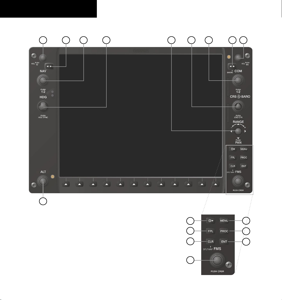
1.1 PFD/MFD CONTROLS
Figure 1-1 PFD/MFD Controls
421 6
5
7
9
8
3
17
12
13
11
10
16
15
14

190-00645-00 Rev. A
Garmin G1000 Cockpit Reference Guide for the Quest Kodiak 100
1-3
SECTION 1
SYSTEM OVERVIEW
The same controls and keys are found on both PFDs
and the MFD.
(1) NAV VOL/ID Knob – Controls the NAV audio
level. Press to turn the Morse code identifier ON and OFF.
Volume level is shown in the field as a percentage.
(2) NAV Frequency Transfer Key – Switches the standby
and active NAV frequencies.
(3) Dual NAV Knob – Tunes the MHz (large knob)
and kHz (small knob) standby frequencies for the NAV
receiver. Press to move the tuning cursor (light blue box)
between the NAV1 and NAV2 fields.
(4) Heading Knob – Turn to manually select a heading
on the HSI. When pressed, it synchronizes the heading
bug with the compass lubber line.
(5) Joystick – Changes the map range (distance top to
bottom of map display) when rotated. Activates the map
pointer when pressed.
(6) CRS/BARO Knob – The large knob sets the altimeter
barometric pressure and the small
knob adjusts the course.
The course is only adjustable when the HSI is in VOR1,
VOR2, or OBS/SUSP mode. Pressing this knob centers
the CDI on the currently selected VOR.
(7) Dual COM Knob – Tunes the MHz (large knob)
and kHz (small knob) standby frequencies for the COM
transceiver. Pressing this knob moves the tuning cursor
(light blue box) between the COM1 and COM2 fields.
(8) COM Frequency Transfer Key – Switches the
standby and active COM frequencies. Pressing and holding
this key for two seconds automatically tunes the emergency
frequency (121.5 MHz) in the active frequency field.
(9) COM VOL/SQ Knob – Controls COM audio level.
Pressing this knob turns the COM automatic squelch ON
and OFF. Audio volume level is shown in the field as a
percentage.
(10) Direct-to Key – Allows the user to enter a destination
waypoint and establish a direct course to the selected
destination (specified by the identifier, chosen from the
active route, or taken from the map pointer position).
(11) FPL Key – Displays the active Flight Plan Page for
creating and editing the active flight plan, or for accessing
stored flight plans.
(12) CLR Key (DFLT MAP) – Erases information,
cancels an entry, or removes page menus. To display the
Navigation Map Page immediately, press and hold CLR
(MFD only).
(13) Dual FMS Knob – Used to select the page to be
viewed (only on the MFD). The large
knob selects a page
group (MAP, WPT, AUX, NRST), while the small knob
selects a specific page within the page group. Pressing the
small knob turns the selection cursor ON and OFF.
(14) MENU Key – Displays a context-sensitive list of
options. This list allows the user to access additional
features, or to make setting changes that relate to certain
pages.
(15) PROC Key – Selects approaches, departures and
arrivals from the flight plan. If a flight plan is used,
available procedures for the departure and/or arrival
airport are automatically suggested. If a flight plan is not
used, the desired airport and the desired procedure may
be selected. This key selects IFR departure procedures
(DPs), arrival procedures (STARs) and approaches (IAPs)
from the database and loads them into the active flight
plan.
(16) ENT Key – Accepts a menu selection or data entry.
This key is used to approve an operation or complete data
entry. It is also used to confirm selections and information
entries.
(17) Dual ALT Knob – Sets the reference altitude in the
box located above the Altimeter. The large knob selects the
thousands, while the small knob selects the hundreds.
190-00645-00 Rev. A
Garmin G1000 Cockpit Reference Guide for the Quest Kodiak 100
1-4
SECTION 1
SYSTEM OVERVIEW
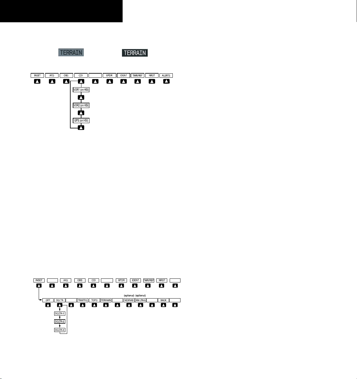
1.2 PFD SOFTKEYS
Softkey OFF
Softkey ON
Figure 1-2 PFD Top Level Softkeys
INSET – Press to display the Inset Map in the lower
left corner of the PFD.
OFF
– Press to remove the Inset Map.
DCLTR
(3) – Press momentarily to select the desired
amount of map detail. The declutter level appears
adjacent to the DCLTR Softkey.
• No declutter: All map features are visible
• Declutter – 1: Declutters land data
• Declutter – 2: Declutters land and SUA data
• Declutter – 3: Removes everything except the active
flight plan
TRAFFIC
– Press to display traffic on the inset map.
TOPO
– Press to display topographical data (i.e.,
coastlines, terrain, rivers, lakes) and elevation
scale on the Inset Map.
Press the BACK or OFF Softkey
to return to the top-level softkeys.
ALERTS
ALERTS
Figure 1-3 INSET Softkeys
TERRAIN
– Press to display terrain information on
the Inset Map.
STRMSCP (optional)
– Press to display the
Stormscope lightning data on the Inset Map
(within a 200 nm radius of the aircraft).
NEXRAD (optional)
– Press to display NEXRAD
precipitation data on the Inset Map.
XM LTNG (optional)
– Press to display the XM Radio
lightning data on the Inset Map.
BACK
– Press to return to the previous level softkey
configuration.
ALERTS
– Press to display the Alerts Window.
190-00645-00 Rev. A
Garmin G1000 Cockpit Reference Guide for the Quest Kodiak 100
1-5
SECTION 1
SYSTEM OVERVIEW
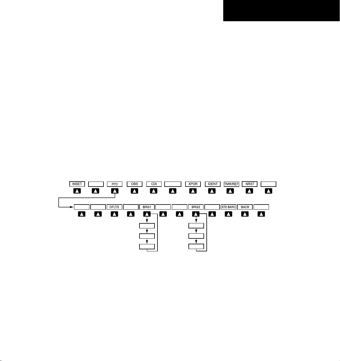
PFD – Press to display the additional softkeys for
additional configuration of the PFD.
METRIC
– Press to display the current and reference
altitudes in meters, in addition to feet. Pressing
the metric softkey also changes the barometric
setting to hectopascals.
DFLTS
– Press to reset default settings on the PFD.
BRG1 (bearing)
– Press to cycle through the
following information:
NAV1
– Displays NAV1 waypoint frequency or
identifier in the BRG1 Information Window.
GPS
– Displays GPS waypoint identifier and GPS
distance information in the BRG1 Information
Window.
OFF
– Removes the BRG1 In f o rmation
Window.
Figure 1-4 PFD Configuration Softkeys
Press the STD BARO or
BACK Softkey to return to
the top-level softkeys
BRG2 (NAV2)
BRG2 (GPS)
BRG2 (OFF
)
BRG1 (NAV1
)
BRG1 (GPS)
BRG1 (OFF
)
ALERTS
ALERTS
METRIC
ARC HSI360 HSI
360 HSI
– Press to display the 360° compass rose.
ARC HSI
– Press to display the 140° viewable arc.
BRG2 (bearing)
– Press to cycle through the
following information:
NAV2
– Displays NAV2 waypoint frequency or
identifier in the BRG2 Information Window.
GPS
– Displays GPS waypoint identifier and GPS
distance information in the BRG2 Information
Window.
OFF
– Removes the BR G 2 Informat i o n
Window.
STD BARO
– Press to set the barometric pressure to
29.92 inches of mercury (1013 hPa by pressing
the METRIC Softkey).
BACK
– Press to return to the previous level
softkeys.
ALERTS
– Press to display the Alerts Window.
190-00645-00 Rev. A
Garmin G1000 Cockpit Reference Guide for the Quest Kodiak 100
1-6
SECTION 1
SYSTEM OVERVIEW
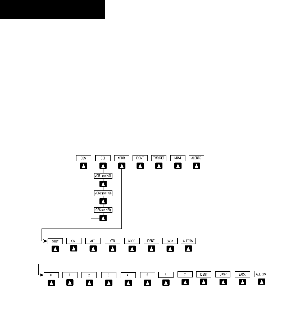
OBS – Press to select OBS mode on the CDI when
navigating by GPS (only available with active leg).
CDI – Press to change navigation mode on the CDI
between GPS, VOR1, and VOR2.
XPDR – Press to display the transponder mode
selection softkeys.
STBY
– Press to select standby mode.
ON
– Press to select mode A.
ALT
– Press to select altitude reporting mode.
VFR
– Press to automatically squawk 1200 (only
in the U.S.A., refer to ICAO standards for VFR
codes in other countries).
CODE
– Press to display transponder code selection
softkeys 0-7.
0 through 7
– Press numbers to enter code.
IDENT
– Press to provide special aircraft
position identification to Air Traffic Control
(ATC).
Press the BACK Softkey
to return to the top level
softkeys
Press the BACK
Softkey to retur
n
to the top level
softkeys
Figure 1-5 XPDR (Transponder Softkeys
BKSP
– Press to remove numbers entered one
at a time.
BACK
– Press to return to the previous level
softkeys.
IDENT
– Press to provide special aircraft position
identification to Air Traffic Control (ATC).
BACK
– Press to return to the previous level
softkeys.
ALERTS
– Press to display the Alerts Window.
IDENT – Press to provide special aircraft position
identification to Air Traffic Control (ATC).
TMR/REF – Press to display the Timer/References
Window.
NRST – Press to display the Nearest Airports
Window.
ALERTS – Press to display the Alerts Window.
190-00645-00 Rev. A
Garmin G1000 Cockpit Reference Guide for the Quest Kodiak 100
1-7
SECTION 1
SYSTEM OVERVIEW
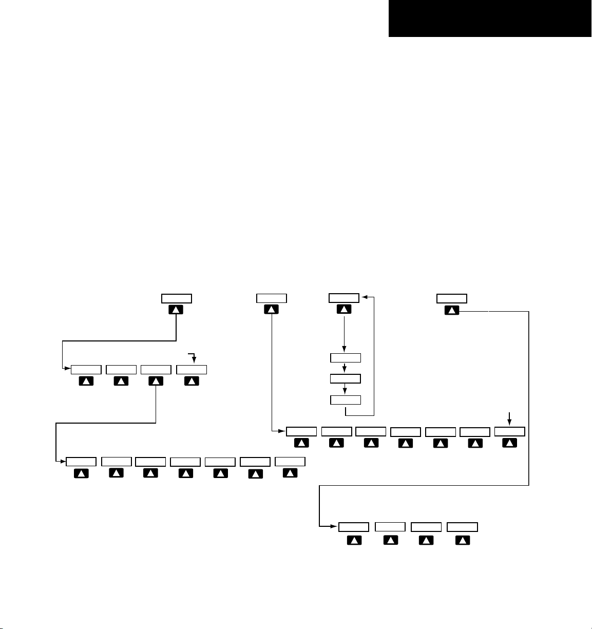
1.3 MFD SOFTKEYS
ENGINE – Pressing this softkey makes available the Engine
Display functions. Refer to the Engine Indication
System section.
MAP – Pressing this softkey enables the following
softkeys:
TRAFFIC – Pressing this softkey displays/removes
Traffic on the Navigation Map.
TOPO – Pressing this softkey displays or removes
topographic information on the Navigation Map.
TERRAIN – Pressing this softkey displays/removes
terrain and obstacle data on the Navigation Map.
Figure 1-6 MFD Softkeys
MAP
DCLTR
TRAFFIC
TOPO
TERRAIN
DCLTR-2
DCLTR-3
DCLTR-1
BACK
Press to return to the
top softkey level
CHKLIST
EXIT
EMERGCY
ENGINE
DONE
The DONE Softkey changes to UNDO when the checklist
item is already checked
STRMSCP
NEXRAD
XM LTNG
(optional)
(optional) (optional)
BACK
ENGINE
ENGINE
ENGINE
BACK
SYSTEM
Press the BACK Softkey on this level to
return to the top softkey level
RST FUEL
DEC FUEL
INC FUEL
(optional)
FUEL
SYSTEM
FUEL
STRMSCP (optional) – Pressing this softkey displays/
removes Stormscope lightning data on the Navigation
Map.
NEXRAD (optional) – Pressing this softkey displays/
removes precipitation data on the Navigation Map.
XM LTNG (optional) – Pressing this softkey displays/
removes XM Radio lightning data on the Navigation
Map.
BACK – Pressing this softkey displays the ENGINE and
MAP top level softkeys.
DCLTR (declutter) – Pressing this softkey removes map
information in three levels.
190-00645-00 Rev. A
Garmin G1000 Cockpit Reference Guide for the Quest Kodiak 100
1-8
SECTION 1
SYSTEM OVERVIEW
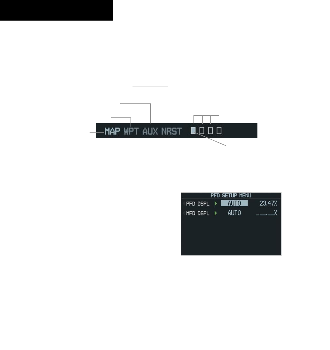
1.4 MFD PAGE GROUPS
1) Turn the large
FMS
Knob until the desired page
group is selected.
2) Turn the small
FMS
Knob to select pages within
the group. See Figure 1-8.
Figure 1-7 Page Group Icon
Map Page Group
Waypoint Page Group
Auxiliary Page Group
Nearest Group
Selected Page
Number of Pages in Current
Group
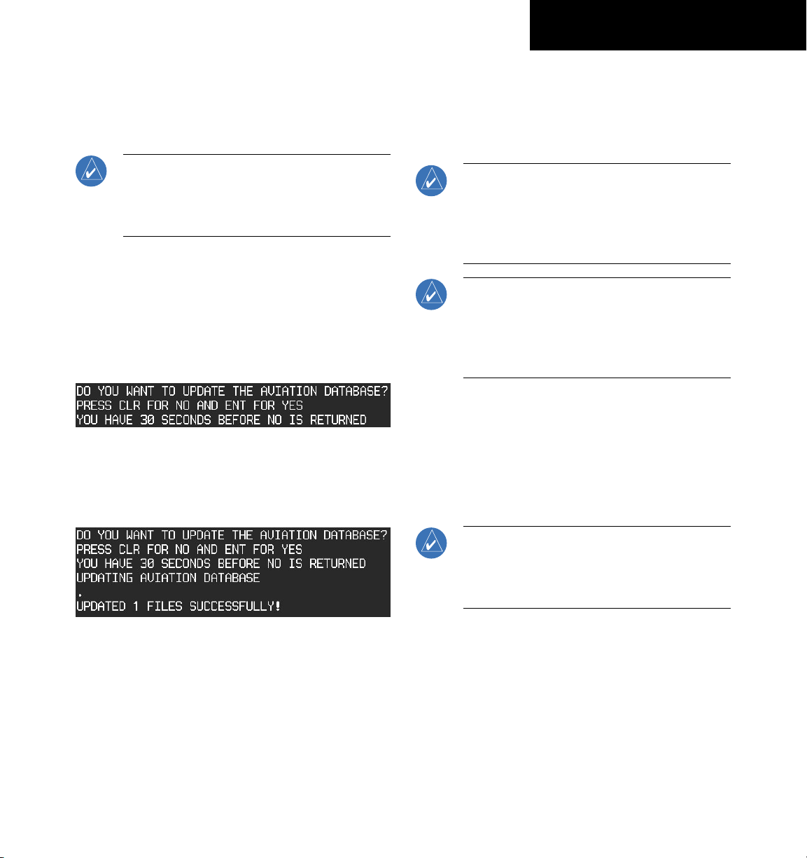
1.5 BACKLIGHTING
To manually adjust the backlight for the
PFD and MFD:
1) Press the
MENU Key on the PFD to display the
PFD Setup Menu Window.
2) Press the small FMS Knob to activate the cursor.
‘PFD DSPL > AUTO’ is now highlighted.
3) Turn the small FMS Knob to display the
selection window.
4) Turn the FMS Knob to select ‘MANUAL’, then
press the ENT Key.
5) With the intensity value now highlighted, turn
the small FMS Knob to select the desired
backlighting.
6) Turn the large FMS Knob to highlight ‘MFD
DSPL > AUTO’ and repeat steps 3 through 5.
Figure 1-8 PFD Setup Menu Window
190-00645-00 Rev. A
Garmin G1000 Cockpit Reference Guide for the Quest Kodiak 100
1-9
SECTION 1
SYSTEM OVERVIEW
1.6 DATABASE UPDATES
Aviation Database Update
NOTE: The display downloads the aviation
database and stores it internally. The aviation
database SD card is not required to remain in
the display after the update.
1) With the G1000 System OFF, insert the aviation
database update SD card into the top card slot
of the PFD (Label of SD card facing left).
2) Turn the G1000 System ON. This prompt
is displayed on the upper left corner of the
PFD:
Figure 1-9 Database Update Prompt
3) Press the ENT Key to confirm the database
updated. This prompt is displayed:
Figure 1-10 Database Update Confirmation
4) After the update completes, the PFD starts in
normal mode. Remove the aviation database
update SD card from the PFD.
5) Turn the G1000 System OFF.
6) Repeat steps 1 through 4 for the MFD. The
MFD and PFD aviation databases are now
updated.
7) Verify that the correct update cycle is loaded
during startup of the MFD.
Terrain and Obstacle Database Updates
NOTE: The data contained in the terrain and
obstacle databases comes from government
agencies. Garmin accurately processes and
cross-validates the data, but cannot guarantee
the accuracy and completeness of the data.
NOTE: Obstacles 200’ and higher are included in
the obstacle database. It is very important to note
that not all obstacles are necessarily charted and
therefore may not be contained in the obstacle
database.
These databases are not stored internally in the MFD
or PFD. Supplemental Data Cards containing identical
database versions must be kept in both displays to retain
terrain and obstacle data. A Supplemental Data Card
should be inserted into the bottom card slot of the PFD
and MFD.
NOTE: If the Supplemental Data Card is
removed from the display, the TOPO and
TERRAIN Softkeys are not functional and are
grayed out on the MFD Map Page.
1) Insert one card in the bottom card slot of the
MFD and one in the bottom card slot of the
PFD.
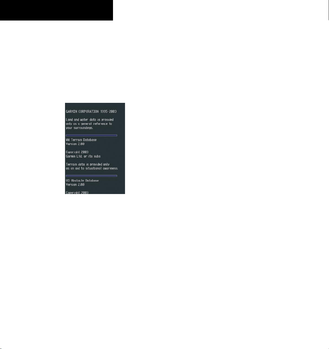
2) Apply power to the G1000 System. View the
MFD power-up splash screen. Check that the
Terrain and Obstacle databases are initialized
and displayed on the scrolling window of the
splash screen.
190-00645-00 Rev. A
Garmin G1000 Cockpit Reference Guide for the Quest Kodiak 100
1-10
SECTION 1
SYSTEM OVERVIEW
3) Acknowledge the Power-up Page agreement
by pressing the
ENT
Key or the right most
softkey.
4) At the MAP – NAVIGATION MAP page, select
the
MAP
Softkey and check to make sure that
the
TOPO
and
TERRAIN
softkeys are functional
(not grayed out).
5) Power down the G1000.
Figure 1-11 Power-Up Splash Screen Window
190-00645-00 Rev. A
Garmin G1000 Cockpit Reference Guide for the Quest Kodiak 100
2-1
SECTION 2
FLIGHT INSTRUMENTS
SECTION 2: FLIGHT INSTRUMENTS
The following discussions pertain to the Primary Flight Display, unless otherwise indicated.
6
7
11
14
15
8
13
12
5
3
4
2
1
16
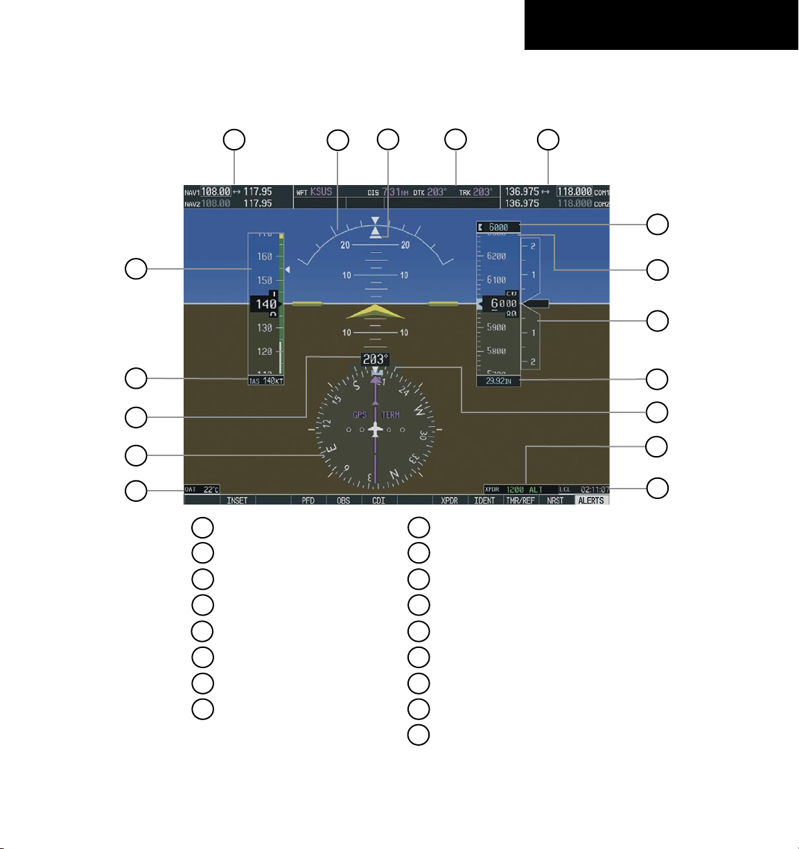
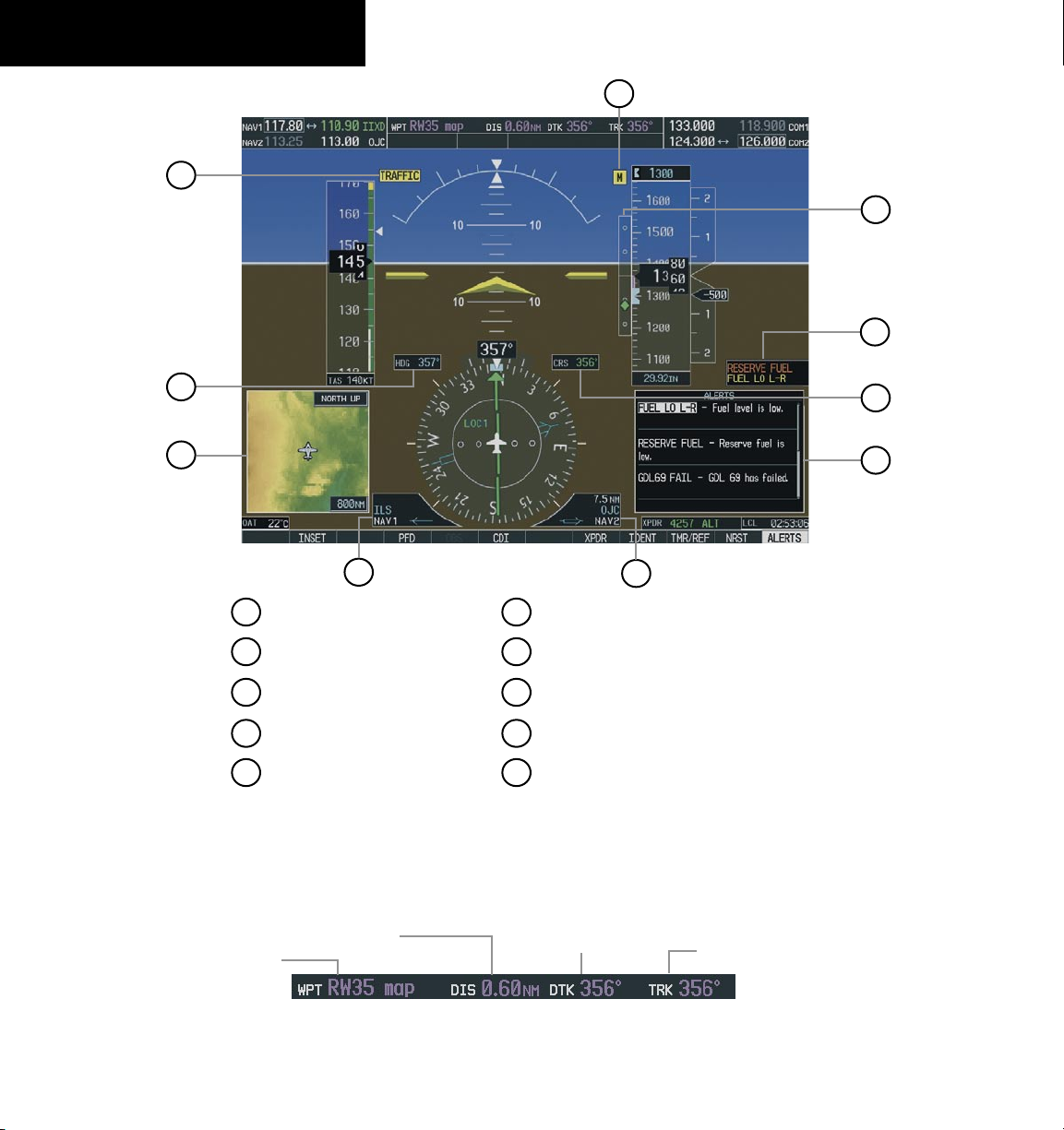
Figure 2-1 Default PFD Information
14
15
11
13
12
9
6
4
2
5
16
7
3
1
NAV Frequency Window
Airspeed Indicator
True Airspeed Box
Outside Air Temperature Box
Selected Altitude Box
Horizontal Situation Indicator
Heading Box
System Time Box
Transponder Status Bar
Barometric Setting Box
Vertical Speed Indicator
Altimeter
COM Frequency Window
Navigation Status Window
10
8
Slip/Skid Indicator
Turn Rate Indicator
10
9
17
17
Attitude Indicator
190-00645-00 Rev. A
Garmin G1000 Cockpit Reference Guide for the Quest Kodiak 100
2-2
SECTION 2
FLIGHT INSTRUMENTS
Figure 2-2 Additional PFD Information
4
6
7
8
1
3
5
2
10
Traffic Annunciation
2
4
3
1
7
8
Inset Map
Selected Course Box
Annunciation Window
6
Alerts Window
Vertical Deviation/
Glideslope Indicator
Marker Beacon Annunciation
Selected Heading Box
5
9
BRG1 Information Window
BRG2 Information Window
10
9
Figure 2-3 PFD Navigation Status Window
Next Waypoint
Distance to Next Waypoint
Desired Track to
Next Waypoint
Current Track
190-00645-00 Rev. A
Garmin G1000 Cockpit Reference Guide for the Quest Kodiak 100
2-3
SECTION 2
FLIGHT INSTRUMENTS
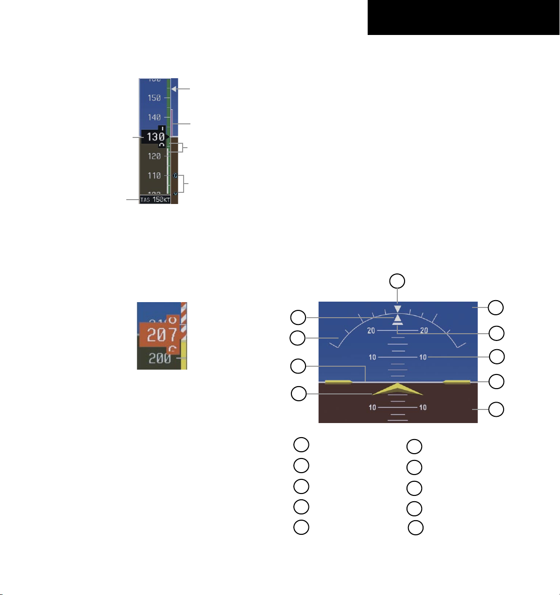
2.1 AIRSPEED INDICATOR
Actual
Airspeed
Airspeed
Trend Vector
True Airspeed
Box
Vspeed
References
Speed
Ranges
Figure 2-4 Airspeed Indicator
Max Speed
for Approach
Flap Setting
Speed Indication
The indicated airspeed is displayed inside the black
pointer. The pointer will become red upon reaching
Vne.
Figure 2-5 Red Pointer at Vne
Speed Ranges
The color coded speed range strip denotes flaps
operating range, normal operating range, and never
exceed speed (Vne). A red range is also present for low
speed awareness. Refer to the Pilot’s Operating Handbook
(POH) for airspeed limitations and indicator markings.
Airspeed Trend Vector
The end of the trend vector displays approximately
what the airspeed will be in 6 seconds if the current rate
of acceleration/deceleration is maintained.
Vspeed References
Vspeed References are turned on or off in the
Timer/References Window. Press the
TMR/REF Softkey
to display the widow. When active (ON), the Vspeeds are
displayed at their respective locations to the right of the
airspeed scale. To activate the Vspeed References, display
the Timer/Reference Window and turn the large FMS
Knob to place the cursor in the ON/OFF field. Turn the
small FMS Knob to select ON or OFF.
2.2 ATTITUDE INDICATOR
The Slip/Skid Indicator is located under the roll pointer
and moves laterally away from the pointer to indicate
lateral acceleration. One Slip/Skid indicator displacement
is equal to one ball displacement when compared to a
traditional slip/skid indicator.
Figure 2-6 Attitude Indicator
3
2
1
9
8
7
6
5
4
1
2
3
4
5
Roll Scale
Horizon Line
Aircraft Symbol
Land Representation
Roll Pointer
6
7
8
9
Aircraft Wing Tips
Pitch Scale
Sky Representation
Slip/Skid Indicator
Roll Scale Zero
10
10
190-00645-00 Rev. A
Garmin G1000 Cockpit Reference Guide for the Quest Kodiak 100
2-4
SECTION 2
FLIGHT INSTRUMENTS
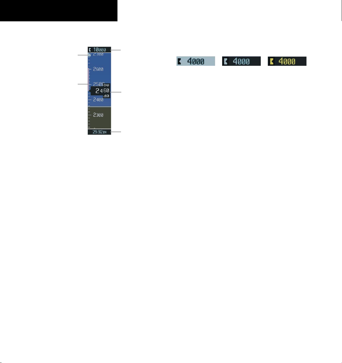
2.3 ALTIMETER
Selected Altitude
Box
Altitude Trend
Vector
Current Altitude
Barometric Setting
Box
Figure 2-7 Altimeter
Altitude Select Bug
Altitude Select Bug
The Altitude Select Bug is displayed at the Selected
Altitude or the edge of the tape (whichever is closer to the
current altitude) to provide increased altitude awareness
and to set the desired hold altitude for the autopilot.
To set the Selected Altitude Bug:
Turn the
ALT
Knobs to set the Altitude Select
Bug. The
small ALT
Knob sets the hundreds and
the
large ALT
Knob sets the thousands. This
altitude also appears in the Selected Altitude
Box above the Altimeter.
Altitude Trend Vector
The end of the trend vector displays approximately
what the altitude will be in 6 seconds if the current rate of
vertical speed is maintained.
Barometric Setting Box
To set barometric pressure, turn the BARO Knob to
select the desired setting.
Altitude Alerting
Figure 2-8 Altitude Alerting Visual Annunciations
Within 1000 ft
Within 200 ft
Deviation of ±200 ft
Visual annunciations appear in the Selected Altitude
Box. Whenever the Selected Altitude is changed,
the Altitude Alerter is reset. The Altitude Alerter is
independent of the Automatic Flight Control System.
An aural tone is heard when the aircraft is within 200
feet of acquiring the selected altitude or when deviating
beyond 200 feet of the acquired selected altitude.
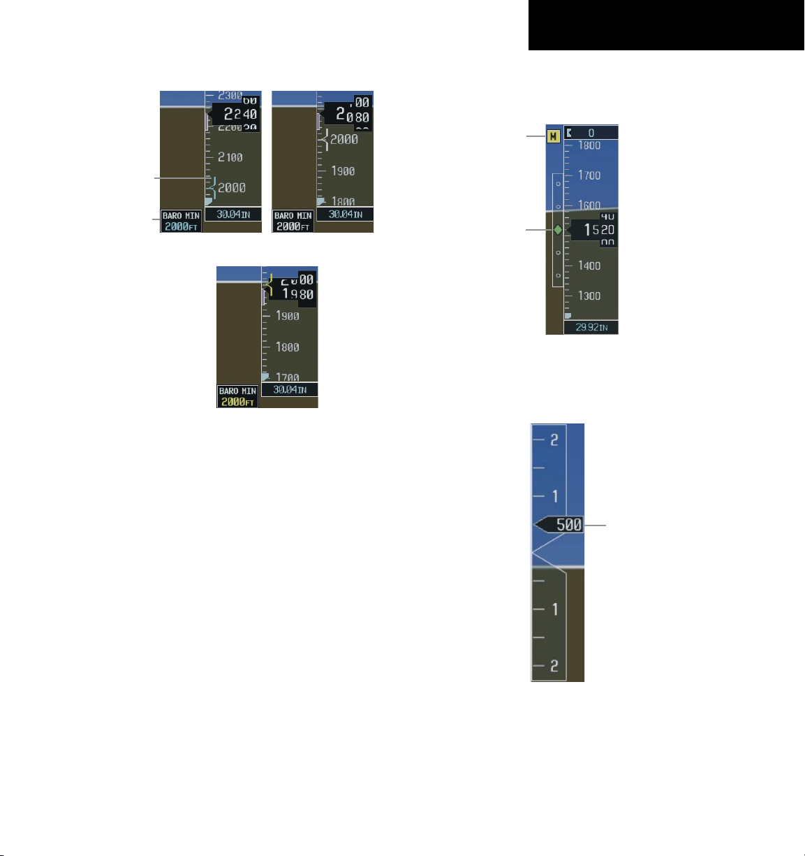
Barometric Minimum Descent Altitude
The desired barometric minimum descent altitude
(MDA, or Decision Height, DH) can be set in the Timer/
References Window.
Visual annunciations alert the pilot when approaching
the MDA:
• When the aircraft altitude descends to within 2500
feet of the MDA setting, the Barometric Minimum
Box appears with the altitude in light blue text.
The bug appears on the tape in light blue once in
range.
• When the aircraft passes through 100 feet of the
MDA, the bug and text turn white.
• Once the aircraft descends past the MDA, the bug
and text turn yellow and the aural alert, “Minimums
Minimums”, is generated.
Alerting is inhibited while the aircraft is on the ground.
If the aircraft climbs after having reached the MDA, once it
reaches 50 feet above the MDA, alerting is disabled.
190-00645-00 Rev. A
Garmin G1000 Cockpit Reference Guide for the Quest Kodiak 100
2-5
SECTION 2
FLIGHT INSTRUMENTS
Within 100 ft
Altitude Reached
Within 2500 ft
Figure 2-9 Barometric Minimum Descent Altitude
Alerting Visual Annunciations
Barometric
Minimum Box
Barometric Mini-
mum Bug
2.4 VERTICAL DEVIATION/GLIDESLOPE
INDICATOR
The Vertical Deviation/Glideslope Indicator appears
when an ILS is tuned in the active NAV field.
2.5 MARKER BEACON ANNUNCIATIONS
Figure 2-10 Marker Beacon and Vertical Deviation
Marker Beacon
Annunciation
Vertical
Deviation/Glideslope
Indicator
2.6 VERTICAL SPEED INDICATOR
Figure 2-11 Vertical Speed Indicator
Vertical Speed Pointer
The actual vertical speed is displayed inside the
pointer.
190-00645-00 Rev. A
Garmin G1000 Cockpit Reference Guide for the Quest Kodiak 100
2-6
SECTION 2
FLIGHT INSTRUMENTS
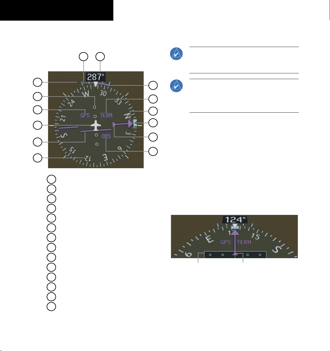
2.7 HORIZONTAL SITUATION INDICATOR
(HSI)
Figure 2-12 Horizontal Situation Indicator (360˚)
8
14
9
6
5
4
3
2
1
7
13
12
11
10
Heading Bug
2
3
6
4
5
7
1
Turn Rate Indicator
Navigation Source
Course Deviation Indicator
TO/FROM Indicator
Course Pointer
Rotating Compass Rose
11
10
12
13
14
9
8
OBS Mode
Lateral Deviation Scale
Flight Phase
Aircraft Symbol
Lubber Line
Heading
Turn Rate and Heading Trend Vector
Arc HSI
NOTE: When the Arc HSI is displayed the BRG1
and BRG2 Information Windows and pointers are
disabled.
NOTE: If the pilot makes a heading change
greater than 105˚ with respect to the course, the
CDI switches to the opposite side of the deviation
scale and displays reverse sensing.
The Arc HSI is a 140˚ expanded section of the compass
rose. The Arc contains a course pointer arrow, the TO/
FROM indicator, a sliding deviation indicator (the TO/
FROM and sliding deviation indicators are one and the
same), and a deviation scale. Upon station passage,
the TO/FROM indicator flips and points to the tail of
the aircraft, just like the conventional TO/FROM flag.
Depending on the navigation source, the CDI on the Arc
HSI can appear in two different ways:
• GPS, OBS, VOR – Arrowhead
• Localizer – Diamond
Lateral
Deviation
Scale
Course Deviation and
TO/FROM Indicator
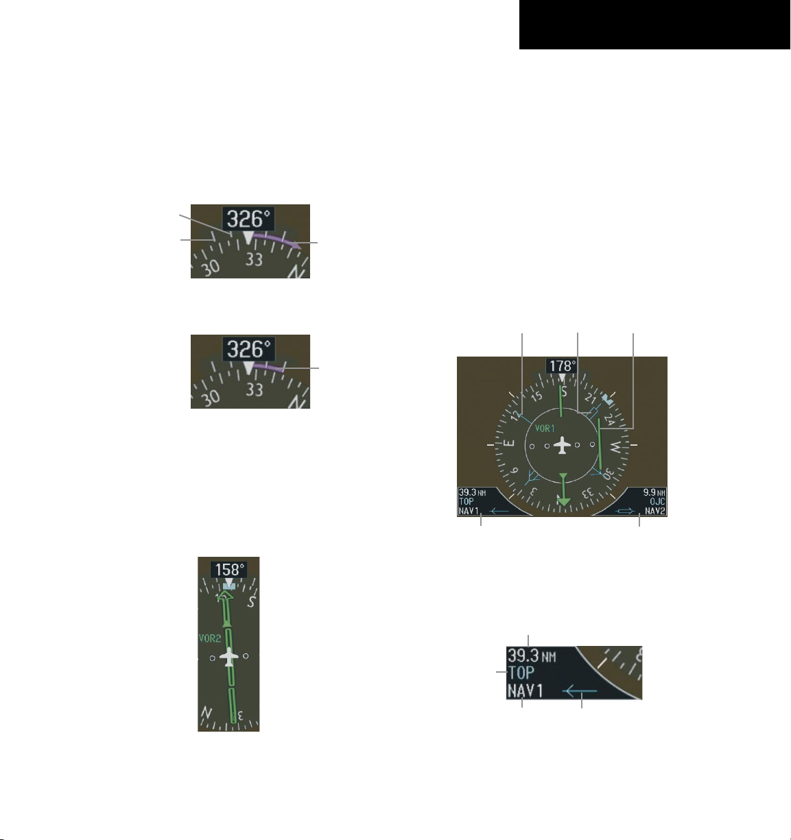
Figure 2-13 Arc HSI
Turn Rate Indicator and Heading Trend Vector
Tick marks to the left and right of the lubber line
denote half-standard and standard turn rates. A magenta
190-00645-00 Rev. A
Garmin G1000 Cockpit Reference Guide for the Quest Kodiak 100
2-7
SECTION 2
FLIGHT INSTRUMENTS
turn rate trend vector shows the current turn rate. The
end of the trend vector gives the heading predicted in six
seconds, based on the present turn rate. At rates greater
than 4 deg/sec, an arrowhead appears at the end of the
magenta trend vector and the prediction is no longer
valid.
Figure 2-15 Standard-Rate Turn Indication
Turn Rate
Trend Vector
(standard rate)
Figure 2-14 Turn Rate Indicator and Trend Vector
Half-Standard Turn
Rate Tick Mark
Standard Turn
Rate Tick Mark
Turn Rate
Trend Vector
(rate > 4
deg/sec)
Course Pointer
The course pointer is a single line arrow (GPS, VOR1
and LOC1) or double line arrow (VOR2 and LOC2) which
points in the direction of the set course.
Figure 2-16 Course Pointer
Course Deviation Indicator (CDI)
The CDI scale automatically adjusts to the current
phase of flight (enroute 5.0 nm, terminal area 1.0 nm,
or approach 0.3 nm). Scaling may be selected manually
from the MFD System Setup Page. See System Setup in
the G1000 Pilot’s Guide for more details.
Bearing Pointers and Information Windows
Pressing the PFD Softkey provides access to the BRG1
and BRG2 Softkeys. The BRG1 pointer is a single line
pointer. The BRG2 pointer is a double line pointer.
Bearing 2
Pointer
Bearing 1
Information
Window
Bearing 1
Pointer
Bearing 2
Information
Window
Figure 2-17 HSI with Bearing Information
CDI
Distance to
Bearing Source
Waypoint
Identifier
Bearing
Source
Pointer
Icon
Figure 2-18 BRG1 Information Window
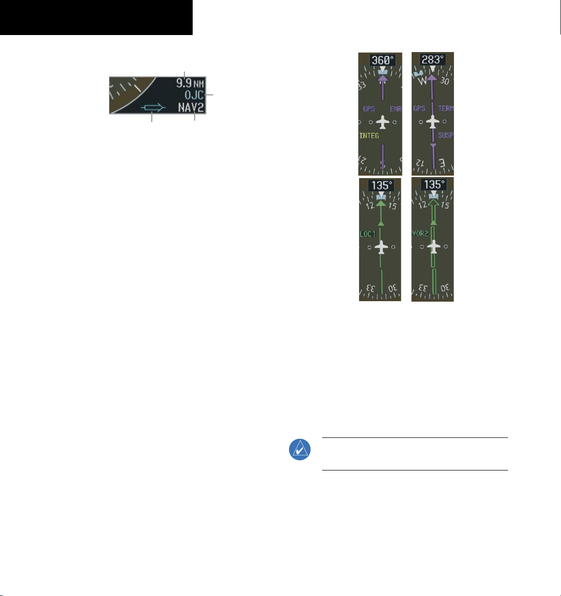
190-00645-00 Rev. A
Garmin G1000 Cockpit Reference Guide for the Quest Kodiak 100
2-8
SECTION 2
FLIGHT INSTRUMENTS
Distance to
Bearing Source
Waypoint
Identifier
Pointer
Icon
Bearing
Source
Figure 2-19 BRG2 Information Window
Navigation Source
To change between navigation sources:
1) Press the CDI Softkey to change from GPS to
VOR1/LOC1.
2) Press the CDI Softkey again to change from
VOR1/LOC1 to VOR2/LOC2.
3) Press the
CDI
Softkey a third time to return to
GPS.
When using GPS as the navigation source, the following
may appear:
• INTEG – GPS information is either not present or
is invalid for navigation use
• WARN – GPS detects a position error
• SUSP – Displayed when in OBS Mode indicating
GPS waypoint sequencing is suspended.
Figure 2-20 GPS INTEG, GPS SUSP, LOC1 and VOR2
To enable/disable OBS mode while navigating
with GPS:
1) Press the
OBS Softkey to select OBS Mode.
2) Turn the CRS Knob to select the desired course
TO/FROM the waypoint.
3) Press the OBS Softkey again to return to
normal operation.
NOTE: The OBS Softkey is only displayed when
navigating an active leg using GPS.
.
Loading...