


Hawker Beechcraft G58
190-01180-02 April 2012 Revision 3
G1000
System Maintenance Manual
Hawker Beechcraft G58
Contains Instructions
For Continued Airworthiness
For STC SA01584WI-D

This page intentionally left blank.
G1000 System Maintenance Manual - Hawker Beechcraft G58 Page A
Revision 3 190-01180-02
© Copyright 2012
Garmin Ltd. or its subsidiaries
All Rights Reserved
Except as expressly provided herein, no part of this manual may be reproduced, copied, transmitted,
disseminated, downloaded or stored in any storage medium, for any purpose without the express prior
written consent of Garmin. Garmin hereby grants permission to download a single copy of this manual
and of any revision to this manual onto a hard drive or other electronic storage medium to be viewed and
to print one copy of this manual or of any revision hereto, provided that such electronic or printed copy of
this manual or revision must contain the complete text of this copyright notice and provided further that
any unauthorized commercial distribution of this manual or any revision hereto is strictly prohibited.
Garmin International, Inc.
1200 E. 151
st
Street
Olathe, KS 66062 USA
Telephone: 913-397-8200
www.garmin.com
Garmin (Europe) Ltd.
Liberty House
Bulls Copse Road
Hounsdown Business Park
Southampton, SO40 9RB, UK
Phone: +44 (0) 23 8052 4000
Fax: +44 (0) 23 8052 4004
RECORD OF REVISIONS
Revision Revision Date Description ECO #
1 5/13/10 Initial release ------
2 5/25/10 Corrected errors in Table 4.1 72258
3 11/28/11 Revised to add -20 GIA and .09 image 89665
DOCUMENT PAGINATION
Section Pagination
Table of Contents i – iv
Section 1 1-1 – 1-4
Section 2 2-1 – 2-6
Section 3 3-1 – 3-24
Section 4 4-1 – 4-6
Section 5 5-1 – 5-6
Section 6 6-1 – 6-6
Section 7 7-1 – 7-4
Section 8 8-1 – 8-11

Page B G1000 System Maintenance Manual - Hawker Beechcraft G58
Revision 3 190-01180-02
INFORMATION SUBJECT TO EXPORT CONTROL LAWS
This document may contain information which is subject to the Export Administration Regulations (“EAR”)
issued by the United States Department of Commerce (15 CFR, Chapter VII Subchapter C) and which
may not be exported, released or disclosed to foreign nationals inside or outside the United States
without first obtaining an export license. The preceding statement is required to be included on any and
all reproductions in whole or in part of this manual.
This product, its packaging, and its components contain chemicals known to the State of California to
cause cancer, birth defects, or reproductive harm. This Notice is being provided in accordance with
California's Proposition 65. If you have any questions or would like additional information, please refer to
our web site at www.garmin.com/prop65.
The GDU lens is coated with a special anti-reflective coating that is very sensitive to skin oils, waxes and
abrasive cleaners. CLEANERS CONTAINING AMMONIA WILL HARM THE ANTI-REFLECTIVE
COATING. It is very important to clean the lens using a clean, lint-free cloth and an eyeglass lens
cleaner that is specified as safe for anti-reflective coatings.
All G1000 screen shots used in this document are current at the time of publication. Screen shots are
intended to provide visual reference only. All information depicted in screen shots, including software file
names, versions and part numbers, is subject to change and may not be up to date.
CAUTION
WARNING
IMPORTANT

G1000 System Maintenance Manual - Hawker Beechcraft G58 Page i
190-01180-02 Revision 3
TABLE OF CONTENTS
PARAGRAPH PAGE
1 INTRODUCTION ................................................................................................................. 1-1
1.1 C
ONTENT, SCOPE, PURPOSE .......................................................................................... 1-1
1.2 O
RGANIZATION ............................................................................................................... 1-1
1.3 D
EFINITIONS/ABBREVIATIONS .......................................................................................... 1-2
1.4 P
UBLICATIONS ................................................................................................................ 1-3
1.5 D
ISTRIBUTION ................................................................................................................. 1-4
2 SYSTEM DESCRIPTION .................................................................................................... 2-1
2.1 E
QUIPMENT DESCRIPTIONS ............................................................................................. 2-1
2.2 O
PTIONAL FEATURES ...................................................................................................... 2-6
3 G1000 CONTROL & OPERATION ..................................................................................... 3-1
3.2 G1000
NORMAL MODE ................................................................................................... 3-1
3.3 R
EVERSIONARY MODE .................................................................................................... 3-2
3.4 C
ONFIGURATION MODE OVERVIEW ................................................................................. 3-3
3.5 C
ONFIGURATION MODE NAVIGATION ............................................................................... 3-3
3.6 G1000
SOFTWARE INFORMATION .................................................................................... 3-5
3.7 G1000
SOFTWARE/CONFIGURATION PROCEDURE ......................................................... 3-11
3.8 SOFTWARE LOAD CONFIRMATION .................................................................................. 3-17
3.9 AVIATION DATABASE LOADING PROCEDURES ................................................................ 3-19
3.10 SVS / PATHWAYS ACTIVATION (OPTION)..................................................................... 3-20
3.11 CHARTVIEW ENABLE PROCEDURE .............................................................................. 3-22
3.12 TAWS-B ENABLE PROCEDURE .................................................................................... 3-23
3.13 AIRCRAFT REGISTRATION NUMBER ENTRY ................................................................. 3-24
3.14 CLEARING DEFAULT USER SETTINGS ......................................................................... 3-24
4 INSTRUCTIONS FOR CONTINUED AIRWORTHINESS ................................................... 4-1
4.1 A
IRWORTHINESS LIMITATIONS ......................................................................................... 4-1
4.2 S
ERVICING INFORMATION ................................................................................................ 4-1
4.3 M
AINTENANCE INTERVALS ........................................................................................... 4-3
5 TROUBLESHOOTING ........................................................................................................ 5-1
5.1 SVS/P
ATHWAYS TROUBLESHOOTING .............................................................................. 5-1
5.2 GTS
820 TROUBLESHOOTING ......................................................................................... 5-2
5.3 S
OFTWARE/CONFIGURATION TROUBLESHOOTING ............................................................ 5-3
5.4 GRT
10 / GRC 10 XM REMOTE CONTROL TROUBLESHOOTING ........................................ 5-4
5.5 S
YSTEM COMMUNICATION HIERARCHY ............................................................................ 5-4
5.6 B
ACKSHELL/BACKPLATE CONNECTORS ........................................................................... 5-5
6 EQUIPMENT REMOVAL & INSTALLATION ..................................................................... 6-1
6.1 GTS
820 TAS PROCESSOR ............................................................................................ 6-1
6.2 GPA
65 LNA/PA ............................................................................................................ 6-2
6.3 TAS ANTENNAS .............................................................................................................. 6-2
6.4 GRT 10 XM REMOTE CONTROL TRANSCEIVER................................................................. 6-3
6.5 GDU
REMOVAL & REPLACEMENT .................................................................................... 6-4
6.6 GMU
44 REMOVAL & REPLACEMENT .............................................................................. 6-5
6.7 GTX
33ES TRANSPONDER REMOVAL & REPLACEMENT ................................................... 6-6
6.8 GIA
63W REMOVAL & REPLACEMENT ............................................................................. 6-7
7 G1000 EQUIPMENT CONFIGURATION & TESTING ........................................................ 7-1

Page ii G1000 System Maintenance Manual - Hawker Beechcraft G58
Revision 3 190-01180-02
7.1 TRANSPONDER TESTING ................................................................................................. 7-1
7.2 GTS
TRAFFIC SYSTEM .................................................................................................... 7-1
8 SYSTEM RETURN TO SERVICE PROCEDURE ............................................................... 8-1
8.1 D
ISPLAY TESTING ........................................................................................................... 8-1
8.2 GIA
63W INTEGRATED AVIONICS UNIT ............................................................................ 8-6
8.3 GFC
700 AUTOPILOT GROUND CHECKS .................................................................. 8-8
8.4 MAINTENANCE RECORDS .............................................................................................. 8-13

G1000 System Maintenance Manual - Hawker Beechcraft G58 Page iii
190-01180-02 Revision 3
LIST OF ILLUSTRATIONS
FIGURE PAGE
Figure 2.1. Display Unit .............................................................................................................. 2-1
Figure 2.2. Transponder ............................................................................................................ 2-2
Figure 2.3. Magnetometer .......................................................................................................... 2-2
Figure 2.4. GTS Receiver .......................................................................................................... 2-3
Figure 2.5 GPA 65 PA/LNA Module .......................................................................................... 2-3
Figure 2.6 G58 Traffic Antenna ................................................................................................. 2-4
Figure 2.7 GRT 10 Transceiver ................................................................................................ 2-4
Figure 2.8 GRC 10 Remote Control .......................................................................................... 2-5
Figure 2-9 GIA unit .................................................................................................................. 2-5
Figure 3.1 - G1000 Softkeys ...................................................................................................... 3-1
Figure 3.2 - Normal Mode (with SVS enabled) .......................................................................... 3-2
Figure 3.3 - Normal Mode (without SVS enabled) ..................................................................... 3-2
Figure 3.4 - Display Reversionary Mode .................................................................................... 3-2
Figure 3.5, Configuration Status ............................................................................................... 3-4
Figure 3.6, Data Transmission Indicators ................................................................................. 3-5
Figure 3.8, Software/Configuration Overview ......................................................................... 3-11
Figure 3.9 - Configuration/Software Load Page ....................................................................... 3-14
Figure 3.10 - Option Selection ................................................................................................. 3-15
Figure 5.1 - GTS 820 Mating Connector .................................................................................... 5-5
Figure 5.2 - GTS 820 Mating Connector .................................................................................... 5-5
Figure 5.3 - GPA 65 Connector ................................................................................................. 5-6
Figure 5.4 - GRT 10 Mating Connector ..................................................................................... 5-6
Figure 6.1 - Battery Compartment ............................................................................................. 6-3
Figure 8.1 – MFD Initial Power Up page (format reference) ...................................................... 8-1
Figure 8.2 – PFD Power Up System Annunciations .................................................................. 8-2
Figure 8.3 – Normal Display (without SVS enabled) .................................................................. 8-2
Figure 8.4 – Normal Display (with SVS enabled) ....................................................................... 8-3
Figure 8.5 – PFD Display without SVS enabled ........................................................................ 8-4
Figure 8.6 – PFD with SVS enabled .......................................................................................... 8-5
Figure 8-7 AUX – GPS STATUS Page (MFD) ........................................................................ 8-6
Figure 8.8 - GFC 700 Pre-Flight Test ........................................................................................ 8-9
LIST OF TABLES
TABLE PAGE
Table 1.1 - Required Documents .............................................................................................. 1-3
Table 1.2 - Reference Publications ............................................................................................ 1-3
Table 3.1 - Required Loader Cards ........................................................................................... 3-5
Table 3.2 – SVS Enable Card .................................................................................................. 3-20
Table 4.1 - Maintenance Intervals .............................................................................................. 4-3
Table 5.1 – SVS Troubleshooting .............................................................................................. 5-1
Table 5.2 – SVS Alert Messages ............................................................................................... 5-2

Page iv G1000 System Maintenance Manual - Hawker Beechcraft G58
Revision 3 190-01180-02
This page intentionally left blank

G1000 System Maintenance Manual - Hawker Beechcraft G58 Page 1-1
190-01180-02 Revision 3
1 INTRODUCTION
1.1 CONTENT, SCOPE, PURPOSE
This document provides Instructions for Continued Airworthiness (ICA) for the Garmin G1000
integrated avionics as installed in the Hawker Beechcraft G58 as modified under STC
SA01584WI-D. This document satisfies the requirements for continued airworthiness as
defined by 14 CFR Part 23.1529 and Appendix G. Information in this document is required to
maintain the continued airworthiness of the G1000. This document is intended to be used in
conjunction with the existing Hawker Beechcraft Baron 55 and 58 Maintenance Manual and the
Hawker Beechcraft Baron (Model G58) Maintenance Manual Supplement listed in Table
1.1.
1.1.1 APPLICABILITY
This document applies to all G58 aircraft that have been modified in accordance with STC
SA01584WI-D. The data defining this modification is contained in the Master Drawing List 005-
00606-01.
Modification of an aircraft by this Supplemental Type Certificate (STC) obligates the aircraft
operator to include the maintenance information provided by this document in the operator’s
Aircraft Maintenance Manual and the operator’s Aircraft Scheduled Maintenance Program.
1.2 ORGANIZATION
The following outline briefly describes the organization of this manual:
Section 2: System Description
Provides a complete description of the type design change associated with updating the G1000
system in the Hawker Beechcraft G58 .
Section 3: G1000 Control & Operation
Presents basic control and operation information specifically tailored to maintenance practices.
Basic G1000 Configuration Mode operation is also described.
Section 4: Instructions for Continued Airworthiness
Provides maintenance instructions for continued airworthiness of the G1000 systems.
Section 5: Troubleshooting
Provides troubleshooting information to aid in diagnosing and resolving potential problems with
the G1000.
Section 6: G1000 Equipment Removal & Replacement
Gives instructions for the removal and replacement of G1000 equipment associated with this
modification.
Section 7: G1000 Equipment Configuration & Testing
Gives instructions for loading software, configuring, and testing of G1000 equipment.
Section 8: System Return to Service Procedure
Specifies return-to-service procedures to be performed upon completion of maintenance of the
G1000 system.

Page 1-2 G1000 System Maintenance Manual - Hawker Beechcraft G58
Revision 3 190-01180-02
1.3 DEFINITIONS/ABBREVIATIONS
AFCS: Automatic Flight Control System
CFR: Code of Federal Regulations
DME: Distance Measuring Equipment
VHF: Very High Frequency
AC: Advisory Circular
AFMS: Airplane Flight Manual Supplement
FPGA: Field Programmable Gate Array
FPM: Flight Path Marker
HSDB: High Speed Data Bus
GDU: Garmin Display Unit
GDC: Garmin Air Data Computer
GTS: Garmin Traffic System
GRT: Garmin Remote Transceiver
GTX: Garmin Transponder
GDL: Garmin Datalink
GMU: Garmin Magnetometer
GA: Garmin Antenna
GIA: Garmin Integrated Avionics
GMA: Garmin Audio Panel
GPS: Global Position System
GRS: Garmin AHRS
HSI: Horizontal Situation Indicator
LCD: Liquid Crystal Display
LRU: Line Replaceable Unit
MDL: Master Drawing List
MFD: Multi-Functional Display
PFD: Primary Flight Display
STC: Supplemental Type Certificate
SVS: Synthetic Vision System
TCAS: Traffic Collision Avoidance System
TAWS: Terrain Awareness and Warning System
WAAS: Wide Area Augmentation System
1.3.1 UNITS OF MEASURE
Unless otherwise stated, all units of measure are English units.

G1000 System Maintenance Manual - Hawker Beechcraft G58 Page 1-3
190-01180-02 Revision 3
1.4 PUBLICATIONS
The following documents are required by this maintenance manual to perform maintenance. It
is the responsibility of the owner / operator to ensure latest versions of these documents are
used during operation, servicing or maintenance of the airplane.
Table 1.1 - Required Documents
P/N Description
005-00606-12 General Arrangement, G1000 Update with Options, G58
005-W0029-00 Wiring Diagram, Optional GRT 10, Hawker Beechcraft G58 Update
005-W0030-00 Wiring Diagram, Optional GTS 820, Hawker Beechcraft G58 Update
005-00606-14 GRT 10 Equipment Install, Hawker Beechcraft G58
005-00606-15 GTS 820 Equipment Install, Hawker Beechcraft G58
005-00606-20 GTS 820 Wire Harness Installation, Hawker Beechcraft G58
005-00606-22 GRT 10 Wire Harness Installation, Hawker Beechcraft G58
320-00587-XX Harness and Coax Fabrication, GTS 820 Option, Hawker Beechcraft G58
320-00596-XX Harness Fabrication, GRT 10 Option, Hawker Beechcraft G58
58-590001-1C *
(or subsequent
revision)
Hawker Beechcraft Baron (Model G58) Maintenance Manual Supplement
for Airplanes with Garmin G1000 Equipment Installed
58-590001-5B *
(or subsequent
revision)
Hawker Beechcraft Baron G58 Avionics Wiring Diagram Manual
55-590000-13F *
(or subsequent
revision)
Hawker Beechcraft Baron 55 and 58 Maintenance Manual
* Hawker Beechcraft document
The following publications are recommended to be on hand during the performance of
maintenance activities.
Table 1.2 - Reference Publications
P/N Description
190-01180-01
FAA Approved Airplane Flight Manual Supplement, G1000 Integrated
Avionics Update with Options Including Synthetic Vision/Pathways on
Hawker Beechcraft G58
190-00526-02 Cockpit Reference Guide for the Hawker Beechcraft G58
190-01180-00 Post Installation Checkout Procedures Hawker Beechcraft G58
190-00355-04 GDL 69/69A XM Satellite Radio Activation Instructions
190-00907-00 G1000 System Maintenance Manual
190-00587-00 GTS 8XX/GPA 65 Installation Manual

Page 1-4 G1000 System Maintenance Manual - Hawker Beechcraft G58
Revision 3 190-01180-02
Generic installation manuals for individual Garmin LRUs are also available through the ‘Dealers
Only’ section of the Garmin web site.
1.5 ICA REVISION AND DISTRIBUTION
This document is required for maintaining the continued airworthiness of the aircraft. When this
document is revised, every page will be revised to indicate current revision level.
Garmin Dealers may obtain the latest revision of this document on the Garmin Dealer Resource
Center website.
Owner/operators may obtain the latest revision of this document from the https://fly.garmin.com/
Support page, or by contacting a Garmin dealer, contacting Garmin Product Support at 913-
397-8200, toll free 866-739-5687, or using around the world contact information on
https://fly.garmin.com/.
A Garmin Service Bulletin describing the revision to this document will be sent to Garmin
dealers if the revision is determined to be significant.
G1000 System Maintenance Manual - Hawker Beechcraft G58 Page 2-1
190-01180-02 Revision 3
2 SYSTEM DESCRIPTION
2.1 EQUIPMENT DESCRIPTIONS
The following subparagraphs provide a brief description and picture of each Garmin LRU installed
or replaced by this STC. For all other G1000/GFC 700 LRUs, refer to the Hawker Beechcraft
Baron (Model G58) Maintenance Manual Supplement for Airplanes with Garmin G1000 Equipment
Installed listed in Table 1.1.
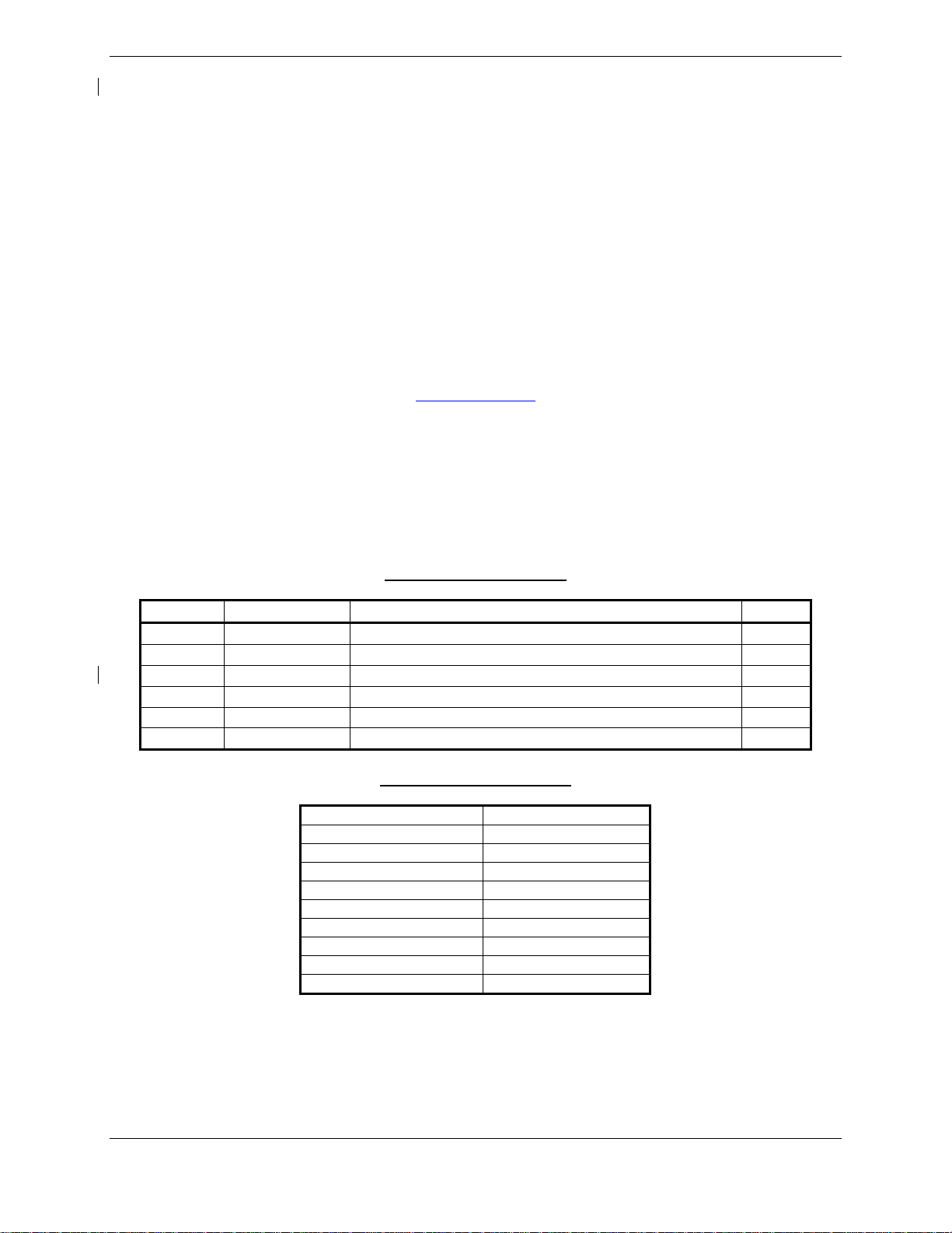
2.1.1 GDU 1040 PFD & GDU 1045 MFD
One Garmin GDU 1040 display and one GDU 1045 display is installed in the Baron instrument
panel. The GDU 104X units, 10.4 inch LCD displays with 1024x768 resolution, are configured as
PFD and an MFD. Both displays provide control and display of nearly all functions of the G1000
integrated cockpit system. The PFD is located on the left side of the MFD.
The GDU 1045 communicates with the GDU 1040, the GDL 69A, and the GWX 68 through a high-
speed data bus (HSDB) Ethernet connection. The GDU 1045 also communicates with the GDL 59
and the GTS 820 through the HSDB via the GDL 69A. The GRS 77 and GDC 74A send
information to the GDU 1045 via ARINC 429 data bus. The display units communicate with each
other and the GIA 63W units through a high-speed data bus (HSDB) Ethernet connection.
This STC installation approves alternate part numbers for these displays that accept external video
input and have an additional HSDB Ethernet connection. There are no mechanical or electrical
interface changes needed for these new part number displays. Refer to the General Arrangement
Drawing 005-00606-12 listed in Table 1.1 for part number information.
NOTE
While the alternate part numbers of displays authorized by this STC include an
external video input and HDSB Ethernet connection, this STC does not approve any
interfaces to these ports. Any interfaces to these ports will require additional
airworthiness approvals.
Figure 2.1. Display Unit

Page 2-2 G1000 System Maintenance Manual - Hawker Beechcraft G58
Revision 3 190-01180-02
2.1.2 GTX 33 TRANSPONDER
The Garmin GTX 33 transponder communicates with the on-side GIA 63W through RS-232 digital
interface. This STC provides for the optional installation of a GTX 33ES transponder that provides
extended squitter functionality. The unit is mounted on the back side of the instrument panel.
There are no mechanical or electrical interface changes needed GTX 33ES option and is installed
in place of the existing GTX 33 if selected. Refer to the General Arrangement Drawing 005-
00606-12 listed in Table 1.1 for part number information.
Figure 2.2. Transponder
2.1.3 GMU 44 MAGNETOMETER
The GMU 44 provides horizontal and vertical magnetic field information to the GRS 77 AHRS.
This allows heading to be calculated and provides assistance during AHRS alignment. The
GMU 44 unit is mounted in L/H wing tip. This STC approved an alternate part number of the
GMU 44. There are no mechanical or electrical interface changes needed for the new
magnetometer and it is installed in place of the existing part if selected. Refer to the General
Arrangement Drawing 005-00606-12 listed in Table 1.1 for part number information.
Figure 2.3. Magnetometer

G1000 System Maintenance Manual - Hawker Beechcraft G58 Page 2-3
190-01180-02 Revision 3
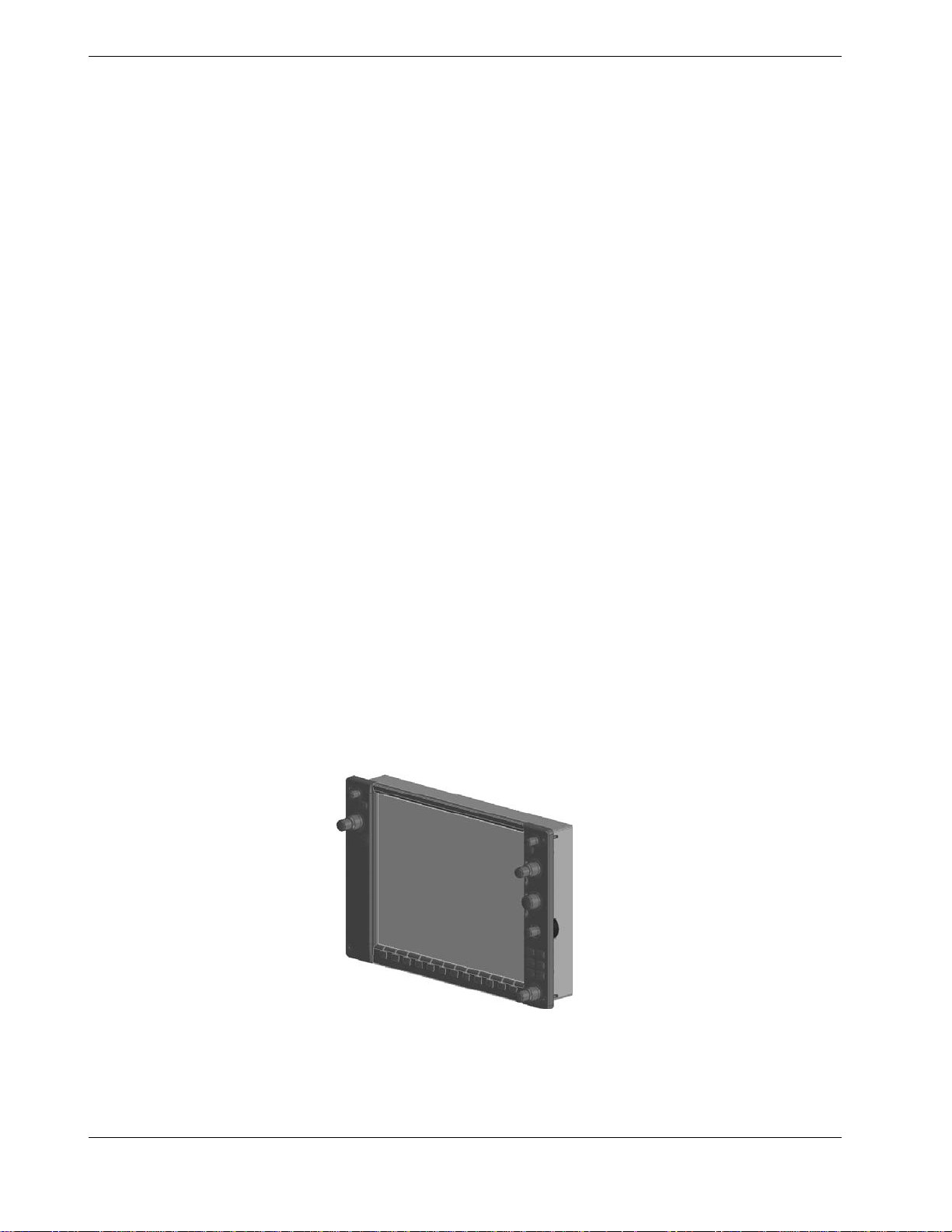
2.1.4 GTS 820 TRAFFIC SYSTEM
The optional GTS 820 system is designed to use active interrogations of Mode S and Mode C
transponders to provide Traffic Advisories (TA) to the pilot. Passive surveillance is available only
when installed with a GTX 33 with extended squitter. Traffic is displayed on the MFD via Ethernet
High Speed Data Bus routed through the existing GDL 69A. The GTS receiver is installed at FS
190. It is powered from the 5 amp Traffic Alert circuit breaker fed from the 28 Vdc Avionics bus.
The GPA 65 is a power amplifier / low noise amplifier (PA/LNA) module installed between the top
antenna and the GTS receiver just forward of FS 140 behind the headliner.. A top GA 58 antenna
is installed on the top of the aircraft just forward of FS 106.25. A lower GA 58 antenna is installed
on the bottom of the aircraft between FS 131.00 and FS 151.00 (standard location) or just forward
of FS 131.00 (optional location)
Figure 2.4. GTS Receiver
Figure 2.5 GPA 65 PA/LNA Module
Page 2-4 G1000 System Maintenance Manual - Hawker Beechcraft G58
Revision 3 190-01180-02
Figure 2.6 G58 Traffic Antenna
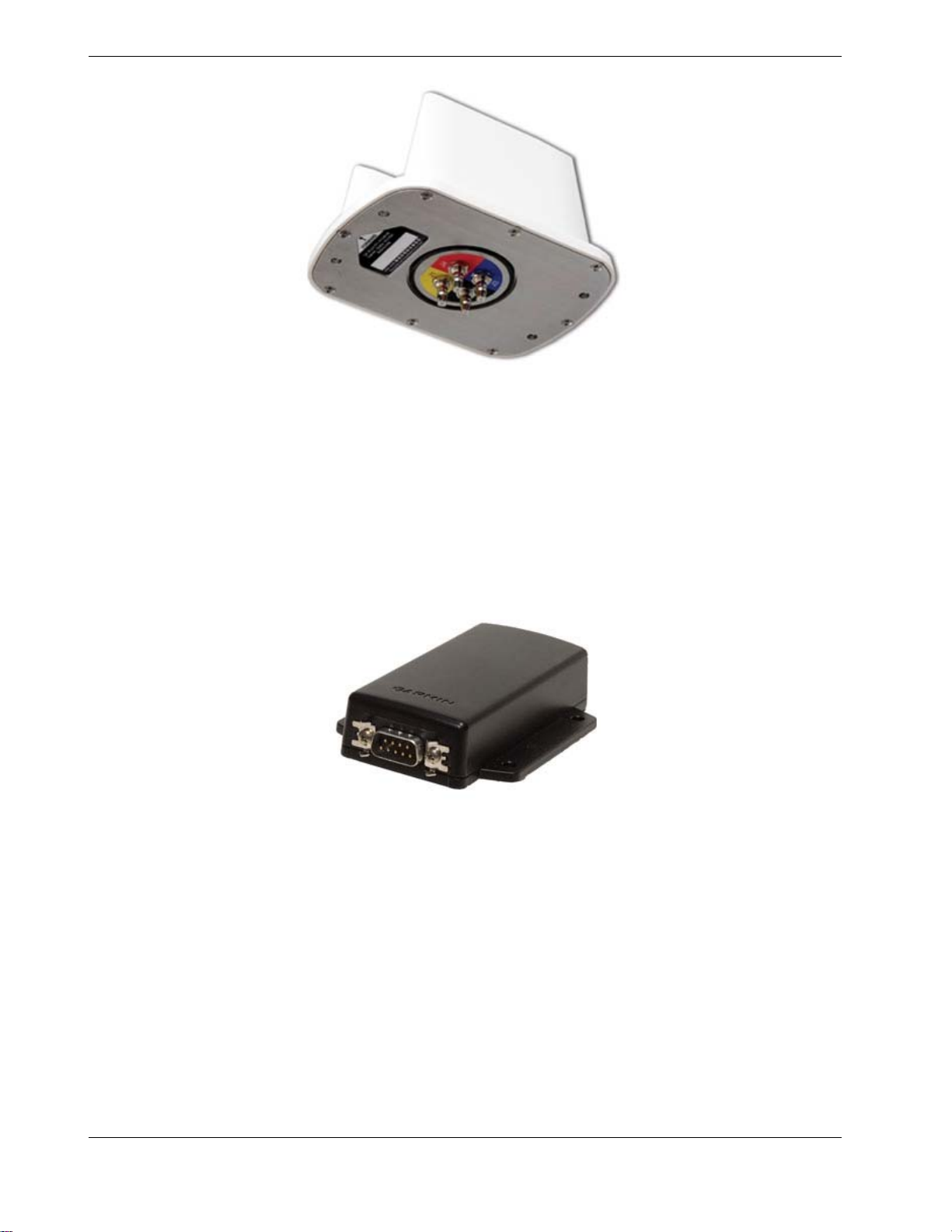
2.1.5 XM REMOTE CONTROL SYSTEM
The optional XM remote control system consists of the GRT 10 transceiver and the GRC Remote
Control. This system allows for remote control of the XM satellite radio function provided by the
existing GDL 69A. The GRT 10 is installed behind the instrument panel on the top of the MFD
system rack. It is powered from the existing 3 amp Datalink circuit breaker off the 28 Vdc Avionics
Bus.
Figure 2.7 GRT 10 Transceiver

G1000 System Maintenance Manual - Hawker Beechcraft G58 Page 2-5
190-01180-02 Revision 3
Figure 2.8 GRC 10 Remote Control
2.1.6 GIA 63W INTEGRATED AVIONICS UNIT (2)
Two Garmin GIA 63W Integrated Avionics Units (IAUs) contain the VHF COM/NAV receivers,
WAAS GPS receiver, Flight Director, and system integration microprocessors. The GIAs also
serve as a communication interface to all other G1000 LRUs in the system. Each GIA 63W
communicates directly with the on-side GDU display using a HSDB Ethernet connection. Both
GIAs are mounted in the systems rack behind the MFD.
GIA 1 is powered through Bus 2 and immediately powers up when the battery 1 or Battery 2
master switch is turned on. GIA #2 receives power through the Avionics Bus and powers up when
the avionics master switch is turned on.
Figure 2-9 GIA unit

Page 2-6 G1000 System Maintenance Manual - Hawker Beechcraft G58
Revision 3 190-01180-02
2.2 OPTI ONAL FEATUR ES
The following optional features are included with this STC. These features are enabled via
individual Enable cards that are to be retained with the aircraft.
• Synthetic Vision and Pathways
• TAWS-B
• Chartview
These features will need to be re-enabled after replacement of a display unit.
G1000 System Maintenance Manual - Hawker Beechcraft G58 Page 3-1
190-01180-02 Revision 3
3 G1000 CONTROL & OPERATION
All control and operation of G1000 equipment as normally used in flight occurs through the PFD,
MFD, and GMA audio panel.
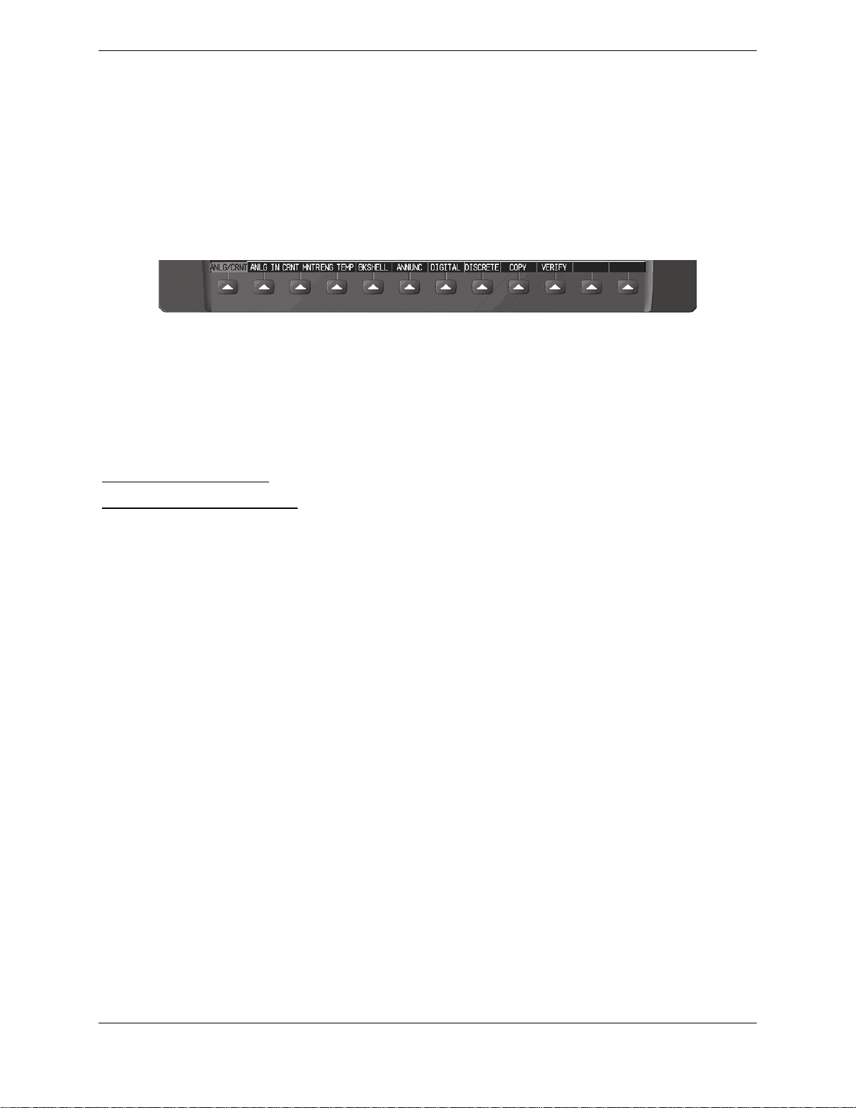
3.1.1 SOFTKEYS
Some pages have commands or selections that are activated by the GDU softkeys. If a softkey
is associated with a command, that command will be displayed directly above the key. A
grayed-out softkey shows a command that is unavailable. A softkey that is highlighted shows
the current active selection.
Figure 3.1 - G1000 Softkeys
3.1.2 FMS KNOB
The FMS knob is the primary control for the G1000 system. Operation is similar to the Garmin
400/500 Series units.
To cycle through different configuration screens:
To change page groups:
Rotate the large FMS knob.
To change pages in a group:
Rotate the small FMS knob.
To activate the cursor for a page, press the small FMS knob directly in, as one would push a
regular button.
To cycle the cursor through different data fields, rotate the large FMS knob.
To change the contents of a highlighted data field, rotate the small FMS knob. This action
either brings up an options menu for the particular field, or in some cases allows the operator to
enter data for the field.
To confirm a selection, press the ENT key.
To cancel a selection, press the small FMS knob in again, deactivating the cursor. The CLR
key may also be used to cancel a selection or deactivate the cursor.
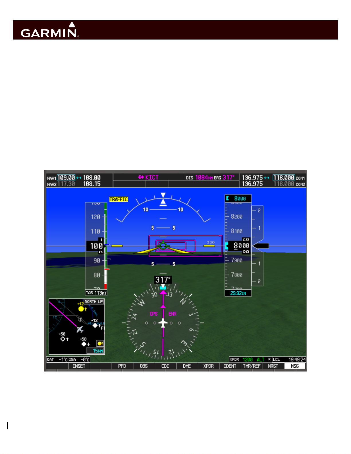
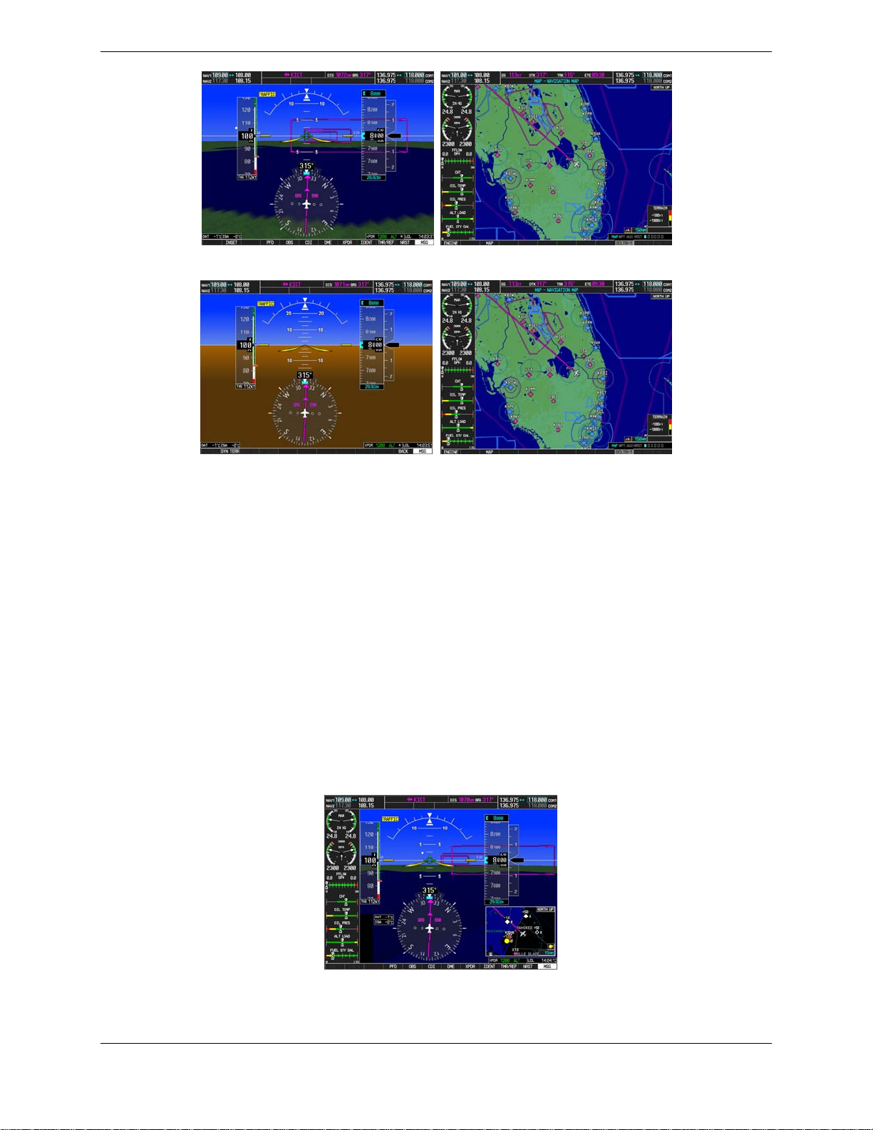
3.2 G1000 NORMAL MODE
To start the G1000 system in Normal Mode:
1. With a ground power unit connected to the external power receptacle, set the L and R BAT
switch to ‘ON’.
2. Set the AVIONICS MASTER switch to ‘ON’.
The G1000 system is now powered in the normal mode. In the normal operating mode, data
fields that are invalid have large red X’s through them. A valid field does not display a red X.
Allow the displays to initialize for approximately one minute. The PFD and MFD will function as
specified in the Cockpit Reference Guide for the Hawker Beechcraft G58 when the system has
been correctly installed and configured.
Page 3-2 G1000 System Maintenance Manual - Hawker Beechcraft G58
Revision 3 190-01180-02
Figure 3.2 - Normal Mode (with SVS enabled)
Figure 3.3 - Normal Mode (without SVS enabled)
3.3 REVE RSIONARY MODE
Reversionary mode allows for display of information related to safe flight in the event of a
display communication or hardware failure. As installed in the G58, both manual and automatic
reversionary modes are possible. Manual reversionary mode allows the operator to force the
PFD or MFD into reversionary mode by pressing the large red button labeled ‘DISPLAY
BACKUP’ on the GMA audio panel. In addition to the manual mode, the system will detect
when a display failure has occurred and will put the still functioning display into reversionary
mode automatically.
NOTE
When the ‘DISPLAY BACKUP’ button is pushed to exit reversionary mode, there
is a 5-second debounce (or the GDU waits for 5 consecutive seconds) and then
returns to normal mode if no other input is received. If the ‘DISPLAY BACKUP’
button is pushed again during this 5-second interval, the timer will repeat the
count.
Figure 3.4 - Display Reversionary Mode

G1000 System Maintenance Manual - Hawker Beechcraft G58 Page 3-3
190-01180-02 Revision 3
3.4 CONFI GURATION MODE OVERVIEW
The Configuration Mode exists to provide the avionics technician with a means of configuring,
checking, and calibrating various G1000 sub-systems. Troubleshooting and diagnostics
information can also be viewed in this mode.
To start the system in Configuration Mode:
a. Press and hold the ENT key on the MFD while resetting power using the MFD circuit
breaker.
b. Release the ENT key after ‘INITIALIZING SYSTEM’ appears in the upper left corner of the
MFD.
c. Press the ENT key or the YES softkey to update system files if prompted.
d. Repeat steps 1 through 3 on the PFD using the PFD circuit breaker to apply power.
CAUTION:
The Configuration Mode contains certain pages and settings that are critical to
aircraft operation and safety. These pages are protected and cannot be
modified, unless the technician is properly authorized and equipped. However,
most protected pages are viewable to allow system awareness for
troubleshooting.
NOTE
For a complete description and breakdown of each Configuration Mode page,
refer to the G1000 System Maintenance Manual listed in Table 1.2.
3.5 CONFI GUR ATION MODE NAVIGATION
Using the FMS knob, a user can navigate through different pages and page groups in the
Configuration Mode. For complete description and breakdown of each page, refer to the G1000
Line Maintenance & Configuration manual.
System Page Group
1. System Status 6. File Manager 11. System Setup
2. Time Configuration 7. Diagnostics Terminal 12. Manifest Configuration
3. Lighting Configuration 8. OEM Diagnostics 13. Maintenance Log
4. System Audio 9. System Configuration
5. System Upload 10. System Data Path Configuration
GDU Page Group
1. Serial Configuration 4. Diagnostics 7. Airframe Configuration
2. CDU Status Page 5. Ethernet Test 8. TAWS Configuration
3. Key Test 6. Alert Configuration
GIA Page Group
1. Serial Configuration 3. GIA I/O Configuration 5. GIA Status Page
2. GIA RS-485 Configuration 4. GIA Configuration 6. GIA CAN Configuration
GEA Page Group
1. Engine Data 2. GEA Status Page 3. GEA Configuration
GTX Page Group
1. Serial Configuration 2. Transponder Configuration
Page 3-4 G1000 System Maintenance Manual - Hawker Beechcraft G58
Revision 3 190-01180-02
GRS Page Group
1. Inputs Configuration 2. GRS / GMU Calibration
ADC Page Group
1. ADC Configuration 2. GDC Configuration
GFC Page Group
1. GFC Configuration 2. GFC Status
GMA Page Group
1. GMA Configuration
GDL Page Group
1. GDL 69 Config
GWX Page Group
1. GWX Configuration
GTS Page Group
1. GTS Configuration
OTHER Page Group *
1. Stormscope
CAL Page Group
1. Fuel Tank Calibration 2. Flap and Trim Calibration 3. HSCM Calibration
* OTHER Page Group will not be present unless Stormscope is configured ON.
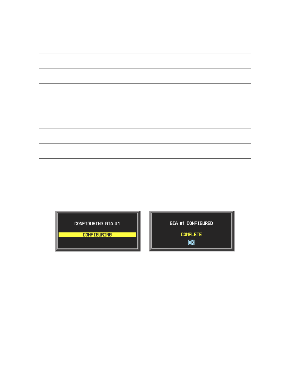
3.5.1 CONFIGURATION PROMPTS
When configuration settings are changed, the technician receives on-screen prompts and/or
confirmations such as those shown in Figure 3.5. Section 7 shows other prompts encountered
during the configuration process.
Figure 3.5, Configuration Status
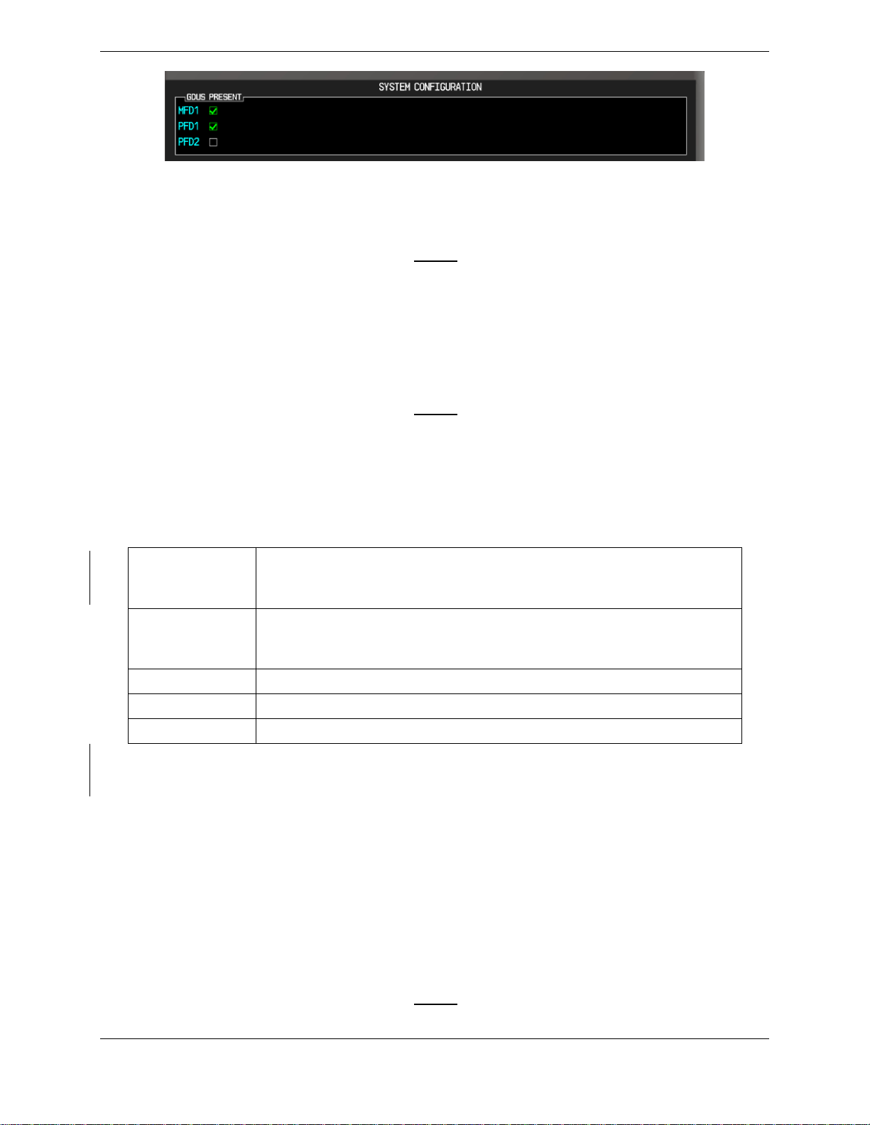
3.5.2 DATA TRANSMISSION INDICATORS
Several configuration screens utilize an indicator light system to show discrete (ON/OFF) data
and/or hardware component status. Unless otherwise noted, the following applies to all such
status indicators:
• Green Checkmark: Expected data is successfully received and is ON. A green check
could also indicate that the parameter/component is working correctly.
• Red X: Expected data is not received. A red X could also indicate that a
parameter/component is invalid.
• White N/A: Expected data is OFF, or no data is expected.
• Amber ?: Data is unknown.
G1000 System Maintenance Manual - Hawker Beechcraft G58 Page 3-5
190-01180-02 Revision 3
Figure 3.6, Data Transmission Indicators
3.6 G1000 SOFTWARE INFORMATION
NOTE
The following sections provide a detailed description of loading all G1000
software and configuration files, which may be excessive for individual
LRU removal and replacement. If removing and replacing individual
LRUs, refer to Section 5.6 of this manual for the necessary steps.
3.6.1 LOADER CARDS
NOTE
The G1000 has various features that require the use of unlock/enable
cards to activate the feature. Throughout this document these cards are
generically referred to as enable cards. In some cases, the actual label
on the physical card may say unlock. If uncertain, the technician should
verify the card part number prior to use.
Table 3.1 - Required Loader Cards
010-00725-08*
or
010-00725-09
G1000/G58 Loader card (contains 006-B0857-08 Software Image)
or
G1000/G58 Loader card (contains 006-B0857-09 Software Image)
010-00330-43
(2 Required) Terrain/Obstacle/Airport/Supplemental Data plus
Garmin Safe Taxi and NOS Flight Charts (Remains in the bottom
slot of the PFD and MFD)
010-00330-50
ChartView Enable Card (see note)
010-00330-51
TAWS Enable Card (see note)
010-00330-54
SVS Enable Card (see note)
* 010-00725-08 Loader Card (006-B0857-08 Software Image) is only compatible with GIA
P/N: 011-01105-01.
3.6.2 G1000 SOFTWARE IMAGE
All software and configuration files were certified by Garmin as part of the FAA-approved Type
Design data. Approved software and hardware definitions are defined on the General
Arrangement drawing 005-00606-12.
G1000 software and configuration files are controlled via the approved software image part
number listed on the General Arrangement drawing 005-00606-12. This software image is
loaded into the G1000 using a software loader card.
NOTE
Installers may obtain the G1000 software image already on a loader
Page 3-6 G1000 System Maintenance Manual - Hawker Beechcraft G58
Revision 3 190-01180-02
card by ordering the Garmin Part Number listed in the General
Arrangement Drawing 005-00606-12 referenced in Table 1.1
IMPORTANT
To satisfy the requirements of this STC it is critical that the technician
install correct software image part number when servicing the G1000
system. Approved software image part numbers are defined on the
General Arrangement Drawing 005-00606-12 listed in Table 1.1
CAUTION
Be cautious when using software loader cards during maintenance. The
G1000 system immediately initializes the card upon power-up. On-
screen prompts must be given careful attention in order to avoid
potential loss of data.
3.6.3 SOFTWARE LOADER CARD CREATION
The software image is an executable self-extracting file which builds the correct file structure
onto an SD card for use loading software to the G1000 and GFC700. To obtain the current file
follow the procedures outlined below.
NOTE
In order to create a loader card, the installer completing these
procedures must be an authorized Hawker Beechcraft service center to
gain access to the necessary data via the Garmin website.
NOTE
Screenshots contained in this section is dependent upon the computer
being used to download the updates and its operating system.
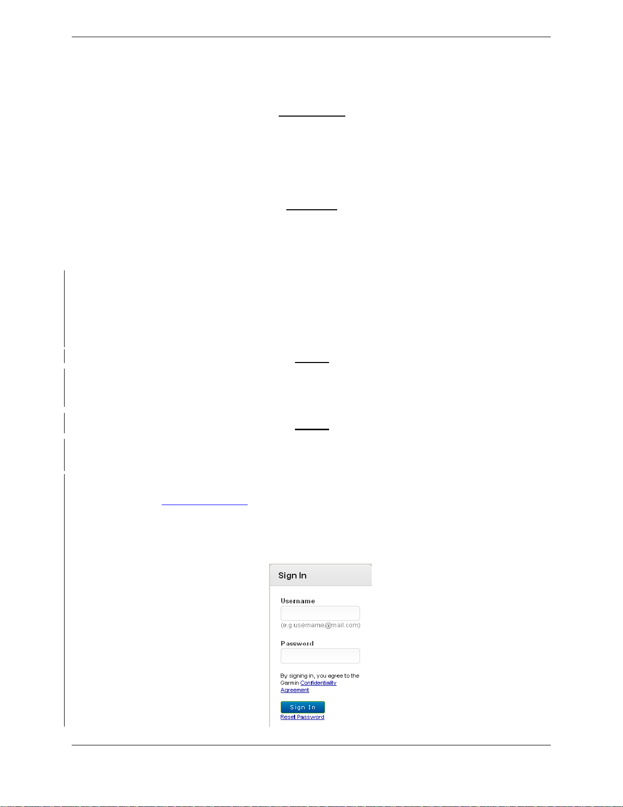
a. Go to www.garmin.com and click on the Dealer Resource Center link in the lower
portion of the home page. Enter User name and Password in the Sign In area at the
left of the page.
Figure 3.7 – Dealer Login
 Loading...