


GTS 8XX
Part 23 AML STC Maintenance Manual with Instructions for Continued Airworthiness
Aircraft Make, Model, Registration Number, and Serial Number, and accompanying STC configuration information in Appendix A, must be completed and saved with aircraft permanent records.
190-01279-01 |
July 2018 |
Revision 2 |

© 2014-2018 Garmin International or its subsidiaries All Rights Reserved
Except as expressly provided herein, no part of this manual may be reproduced, copied, transmitted, disseminated, downloaded or stored in any storage medium, for any purpose without the express prior written consent of Garmin. Garmin hereby grants permission to download a single copy of this manual and of any revision to this manual onto a hard drive or other electronic storage medium to be viewed and to print one copy of this manual or of any revision hereto, provided that such electronic or printed copy of this manual or revision must contain the complete text of this copyright notice and provided further that any unauthorized commercial distribution of this manual or any revision hereto is strictly prohibited.
Garmin®, flyGarmin®, and flyGarmin.com® are registered trademarks of Garmin International or its subsidiaries. GDU™, GDL™, GNS™, GTN™, GTS™, and GTX™ are trademarks of Garmin International or its subsidiaries. These trademarks may not be used without the express permission of Garmin.
Adobe® is a registered trademark of Adobe Systems Incorporated. All rights reserved.
All other product or company names mentioned in this manual are trade names, trademarks, or registered trademarks of their respective owners.
For aviation product support, visit flyGarmin.com.
For information regarding the Aviation Limited Warranty, refer to Garmin’s website.
190-01279-01 |
GTS 8XX Part 23 AML STC Maintenance Manual |
|
Rev. 2 |
Page i |
|

|
|
RECORD OF REVISIONS |
|
|
|
Revision |
Revision Date |
Description |
|
|
|
1 |
05/01/2014 |
Initial Release. |
|
|
|
2 |
07/25/2018 |
Added information pertaining to the GTS 800, 820, and 850. |
|
|
|
|
CURRENT REVISION DESCRIPTION |
|
|
|
|
Section |
Description of Change |
|
|
|
|
|
Updated “GTS Processor” to “GTS 800/820/850/825/855.” |
|
|
|
|
1.3.1 |
Updated “GTS Processor LRU” to “GTS 825 or 855 LRU.” |
|
|
||
|
Added “GTS 8X0 refers to the GTS 800, 820, or 850 LRU at the core of the GTS 8XX |
|
|
system.” |
|
1.4 |
Added GTS 8X0/GPA 65 (GTS 800/GTS 820/GTS 850) Installation (P/N 190-00587-00). |
|
|
|
|
2.3 |
Added GTS 800 and GTS 820/850 requirements to Table 2-1 GTX 8XX System Current |
|
Requirements. |
||
|
||
|
Updated procedure for antenna visual inspection to define inspection criteria. |
|
4.3 |
|
|
Updated procedure for antenna visual inspection - suspected lightning strike to include |
||
|
||
|
inspection criteria. |
|
|
|
|
5.1 |
Added “GTS 8X0 Install Tool (P/N 006-A0242-00).” |
|
|
|
|
5.3 |
Updated “Baro Altitude” fault to “Pressure Altitude” in Table 5-1 GTS 8XX System Faults. |
|
|
|
|
6.1 |
Added Section 6.1 GTS 8X0. |
|
|
|
|
6.2 |
Added Section 6.2 GPA 65. |
|
|
|
|
7.3 |
Added content for GTS 8X0 Install Tool (P/N 006-A0242-00). |
|
|
|
|
7.3.1 |
Added note regarding GTS 8XX install tools. |
|
|
|
|
Appendix A |
Updated title of Appendix A to “Aircraft Installation Record.” |
|
|
|
|
A.2.1 |
Added GDU 7XX equipment reference to Table A-1 GTS 8XX System Interfaces to |
|
Garmin Equipment. |
||
|
||
A.3 |
Updated aircraft profile to Figure A-2 Equipment Location and Wire Routing - Twin |
|
Engine Airplane. |
||
|
||
Appendix B |
Updated title of Appendix B to “Electrical Bonding Procedures.” |
|
|
|
|
|
Added flag notes for Figure B-7. |
|
|
|
|
B.3 |
Added 5:1length-to-width ratio requirement. |
|
|
|
|
|
Added bonding strap restriction of six inches. |
|
|
|
|
B.4 |
Added bonding strap restriction of six inches. |
|
|
|
190-01279-01 |
GTS 8XX Part 23 AML STC Maintenance Manual |
Rev. 2 |
Page ii |
INFORMATION SUBJECT TO EXPORT CONTROL LAWS
This document may contain information that is subject to the Export Administration Regulations (EAR) issued by the United States Department of Commerce (15 CFR, Chapter VII, Subchapter C) and may not be exported, released, or disclosed to foreign nationals inside or outside of the United States without first obtaining an export license.
Information in this document is subject to change without notice. For updates and supplemental information regarding the operation of Garmin products, visit flyGarmin.com.
DEFINITIONS OF WARNINGS, CAUTIONS, AND NOTES
WARNING
A Warning means injury or death is possible.
CAUTION
A Caution means that damage to the equipment is possible.
NOTE
A Note provides additional information.
190-01279-01 |
GTS 8XX Part 23 AML STC Maintenance Manual |
Rev. 2 |
Page iii |

TABLE OF CONTENTS
1 |
INTRODUCTION.............................................................................................................................. |
1-1 |
|
|
1.1 |
Scope .......................................................................................................................................... |
1-2 |
|
1.2 |
Organization ............................................................................................................................... |
1-2 |
|
1.3 |
Definitions and Abbreviations ................................................................................................... |
1-3 |
|
1.4 |
Related Publications................................................................................................................... |
1-3 |
|
1.5 |
Distribution................................................................................................................................. |
1-4 |
2 |
GENERAL DESCRIPTION ............................................................................................................. |
2-1 |
|
|
2.1 |
System Overview ....................................................................................................................... |
2-2 |
|
2.2 |
Equipment Description............................................................................................................... |
2-2 |
|
2.3 |
Electrical Current Requirements ................................................................................................ |
2-2 |
|
2.4 |
Interface Summary ..................................................................................................................... |
2-3 |
|
2.5 |
Ground Plane.............................................................................................................................. |
2-4 |
3 |
CONTROL AND OPERATION....................................................................................................... |
3-1 |
|
4 INSTRUCTIONS FOR CONTINUED AIRWORTHINESS......................................................... |
4-1 |
||
|
4.1 |
Airworthiness Limitations.......................................................................................................... |
4-2 |
|
4.2 |
Servicing Information ................................................................................................................ |
4-2 |
|
4.3 |
Maintenance Intervals ................................................................................................................ |
4-3 |
5 |
TROUBLESHOOTING .................................................................................................................... |
5-1 |
|
|
5.1 |
Troubleshooting Software .......................................................................................................... |
5-2 |
|
5.2 |
Assert Log Diagnosis ................................................................................................................. |
5-3 |
|
5.3 |
System Faults ............................................................................................................................. |
5-4 |
6 EQUIPMENT REMOVAL AND RE-INSTALLATION............................................................... |
6-1 |
||
|
6.1 |
GTS 8X0 .................................................................................................................................... |
6-2 |
|
6.2 |
GPA 65....................................................................................................................................... |
6-2 |
|
6.3 |
GTS Processor............................................................................................................................ |
6-3 |
|
6.4 |
Configuration Module ................................................................................................................ |
6-3 |
|
6.5 |
Antenna Coaxial Cable............................................................................................................... |
6-4 |
|
6.6 |
Directional Antenna ................................................................................................................... |
6-6 |
|
6.7 |
Omni-directional (Monopole) Antenna...................................................................................... |
6-7 |
7 |
RETURN TO SERVICE ................................................................................................................... |
7-1 |
|
|
7.1 |
Maintenance Records ................................................................................................................. |
7-2 |
|
7.2 |
Return to Service Requirements................................................................................................. |
7-2 |
|
7.3 |
Configuration and Checkout ...................................................................................................... |
7-3 |
|
7.4 |
System Checkout........................................................................................................................ |
7-8 |
APPENDIX A AIRCRAFT INSTALLATION RECORD................................................................... |
A-1 |
||
|
A.1 |
General Installation Information ............................................................................................... |
A-2 |
|
A.2 |
Interfaced Equipment ................................................................................................................ |
A-3 |
|
A.3 |
Equipment Locations and Wire Routing................................................................................... |
A-5 |
|
A.4 |
Configuration Log ..................................................................................................................... |
A-8 |
|
A.5 |
Aircraft Wiring Diagrams ......................................................................................................... |
A-9 |
APPENDIX B ELECTRICAL BONDING PROCEDURES............................................................... |
B-1 |
||
|
B.1 |
Considerations for Untreated or Bare Dissimilar Metals .......................................................... |
B-2 |
|
B.2 |
Preparation of Aluminum Surfaces ........................................................................................... |
B-3 |
|
B.3 |
Composite Aircraft.................................................................................................................... |
B-4 |
|
B.4 |
Tube and Fabric Aircraft ........................................................................................................... |
B-9 |
190-01279-01 |
GTS 8XX Part 23 AML STC Maintenance Manual |
|
Rev. 2 |
Page iv |
|

LIST OF FIGURES
Figure 2-1 GTS 8XX System Interface Diagram .................................................................................. |
2-3 |
Figure 3-1 GTS 8XX Traffic System Controls ...................................................................................... |
3-1 |
Figure 5-1 GTS Assert Log Diagnosis Tool .......................................................................................... |
5-3 |
Figure 7-1 GTS Processor Install Tool - Normal Tab ........................................................................... |
7-4 |
Figure 7-2 GTS Processor Install Tool - Configuration Tab ................................................................. |
7-6 |
Figure 7-3 GTS Processor Install Tool - Upload Tab ............................................................................ |
7-7 |
Figure 7-4 GTS Processor Install Tool - Assert Tab ............................................................................. |
7-7 |
Figure 7-5 GTS Processor Install Tool - Normal Tab ........................................................................... |
7-9 |
Figure 7-6 Target Aircraft Position for Traffic Display Flight Check ................................................ |
7-11 |
Figure A-1 Equipment Location and Wire Routing - Single-Engine Airplane .................................... |
A-6 |
Figure A-2 Equipment Location and Wire Routing - Twin Engine Airplane ...................................... |
A-7 |
Figure A-3 GTS 8XX System Configuration Log ................................................................................ |
A-8 |
Figure B-1 Electrical Bonding Preparation – Nut Plate ....................................................................... |
B-2 |
Figure B-2 Electrical Bonding Preparation – Bolt/Nut Joint ................................................................ |
B-2 |
Figure B-3 Electrical Bond Preparation – Terminal Lug ..................................................................... |
B-2 |
Figure B-4 Fiberglass Insulation for Carbon Material ......................................................................... |
B-4 |
Figure B-5 Aluminum Tape Joint ......................................................................................................... |
B-6 |
Figure B-6 Aluminum Tape Ground Termination ................................................................................ |
B-6 |
Figure B-7 GTS Processor Aluminum Tape Installation ..................................................................... |
B-7 |
Figure B-8 Electrical Bonding Using Conductive Clamp .................................................................. |
B-11 |
190-01279-01 |
GTS 8XX Part 23 AML STC Maintenance Manual |
|
Rev. 2 |
Page v |
|

LIST OF TABLES
Table 2-1 GTS 8XX System Current Requirements ............................................................................. |
2-2 |
|
Table 2-2 Ground Plane Definitions and Ground Path Resistance Requirements ................................ |
2-4 |
|
Table 5-1 GTS 8XX System Faults ....................................................................................................... |
5-4 |
|
Table 6-1 |
Recommended Coaxial Cable Length ................................................................................... |
6-5 |
Table 7-1 |
GTS 8XX System Flag Status ............................................................................................... |
7-5 |
Table 7-2 |
Data Source Status Icons ....................................................................................................... |
7-6 |
Table 7-3 |
Ramp Test Intruder Scenario ............................................................................................... |
7-10 |
Table A-1 GTS 8XX System Interfaces to Garmin Equipment ............................................................ |
A-3 |
|
Table A-2 GTS 8XX System Interfaces to Other Equipment ............................................................... |
A-4 |
|
Table A-3 GTS 8XX Equipment Locations .......................................................................................... |
A-5 |
|
Table B-1 Composite Airframe Bonding Strap Assembly .................................................................... |
B-5 |
|
Table B-2 Bonding Strap Assembly for Air-craft with Tubular Airframes ........................................ |
B-10 |
|
190-01279-01 |
GTS 8XX Part 23 AML STC Maintenance Manual |
Rev. 2 |
Page vi |

1 |
INTRODUCTION |
|
|
1.1 |
Scope................................................................................................................................... |
1-2 |
|
1.2 |
Organization........................................................................................................................ |
1-2 |
|
1.3 |
Definitions and Abbreviations ............................................................................................ |
1-3 |
|
1.3.1 |
Definitions................................................................................................................................. |
1-3 |
|
1.3.2 |
Abbreviations ............................................................................................................................. |
1-3 |
|
1.4 |
Related Publications ........................................................................................................... |
1-3 |
|
1.5 |
Distribution ......................................................................................................................... |
1-4 |
|
190-01279-01 |
GTS 8XX Part 23 AML STC Maintenance Manual |
Rev. 2 |
Page 1-1 |

1.1 Scope
This document provides maintenance instructions and Instructions for Continued Airworthiness (ICA) for the GTS 8XX Traffic System as installed under STC SA02121SE. This document satisfies the requirements for continued airworthiness as defined by 14 CFR Part 23.1529 and 14 CFR Part 23 Appendix G.
1.2 Organization
The following outline briefly describes the organization of this manual:
Section 2: System Description
This section provides a description of the equipment installed by this STC. An overview of the GTS 8XX system interface is also provided.
Section 3: Control and Operation
This section provides basic control and operation information in relation to maintenance practices. Basic GTS configuration and software loading is also described.
Section 4: Instructions for Continued Airworthiness
This section provides instructions to maintain continued airworthiness of the GTS 8XX system and system airworthiness limitations.
Section 5: Troubleshooting
This section provides troubleshooting information to diagnose and resolve problems with GTS 8XX system equipment.
Section 6: Equipment Removal and Reinstallation
This section provides instructions for the removal and re-installation of GTS 8XX system equipment.
Section 7: Return to Service
This section specifies return to service procedures to be performed upon completion of maintenance of GTS 8XX system equipment.
Appendix A: Aircraft Installation Record
This appendix is used to record information for a specific GTS 8XX system installation.
Appendix B: Electrical Bonding Procedures
This appendix provides special bonding procedures for non-metallic aircraft.
190-01279-01 |
GTS 8XX Part 23 AML STC Maintenance Manual |
Rev. 2 |
Page 1-2 |

1.3 Definitions and Abbreviations
1.3.1Definitions
“GTS 8XX system” refers to the complete system, including GTS 800/820/850/825/855, antennas, and associated equipment.
“GTS Processor” refers to the GTS 825 or 855 LRU at the core of the GTS 8XX system. “GTS 8X0” refers to the GTS 800, 820, or 850 LRU at the core of the GTS 8XX system.
1.3.2Abbreviations
The following terminology is used within this document:
AML |
Approved Model List |
ADS-B |
Automatic Dependent Surveillance-Broadcast |
CFR |
Code of Federal Regulations |
DME |
Distance Measuring Equipment |
FAA |
Federal Aviation Administration |
HSDB |
High Speed Data Bus |
ICA |
Instructions for Continued Airworthiness |
LRU |
Line Replaceable Unit |
MFD |
Multi-Function Display |
SL |
Sensitivity Level |
STC |
Supplemental Type Certificate |
TA |
Traffic Advisory |
TAS |
Traffic Advisory System |
TCAS |
Traffic Alert and Collision Avoidance System |
TSO |
Technical Standard Order |
In this manual, references to GTS 8XX Part 23 AML STC Installation Manual (P/N 190-01279-00) may be abbreviated as the “STC IM.”
1.4 Related Publications
Part Number |
Document |
005-00738-01 |
Master Drawing List, GTS 8XX Part 23 AML STC |
|
|
005-00738-02 |
Equipment List, GTS 8XX Part 23 AML STC |
|
|
190-00587-00 |
GTS 8X0/GPA 65 (GTS 800/GTS 820/GTS 850) Installation Manual |
|
|
190-00587-02 |
GTS Traffic Systems Pilot’s Guide |
|
|
190-00587-50 |
GTS Processor (GTS 825/855/8000) Installation Manual |
|
|
190-00587-51 |
GTS Processor Maintenance Manual |
|
|
190-01279-00 |
GTS 8XX Part 23 AML STC Installation Manual |
|
|
700704 |
L-Band/DME Blade Antenna P/N L10-611-( ) Limitations and Installation Instructions |
|
|
700784 |
Dayton-Granger Inc. General Installation Instructions for Antennas |
|
|
190-01279-01 |
GTS 8XX Part 23 AML STC Maintenance Manual |
Rev. 2 |
Page 1-3 |
1.5 Distribution
This document contains instructions required to maintain continued airworthiness of the GTS 8XX system. When this document is revised, every page will be revised to indicate the current revision level. Garmin dealers may obtain the latest revision of this document on the Garmin Dealer Resource Center website.
Owner/operators may obtain the latest revision of this document from flyGarmin.com.
A Garmin Service Bulletin describing the revision to this document will be sent to Garmin dealers if the revision is determined to be significant.
190-01279-01 |
GTS 8XX Part 23 AML STC Maintenance Manual |
Rev. 2 |
Page 1-4 |

2 |
GENERAL DESCRIPTION |
|
2.1 |
System Overview................................................................................................................ |
2-2 |
2.2 |
Equipment Description ....................................................................................................... |
2-2 |
2.3 |
Electrical Current Requirements......................................................................................... |
2-2 |
2.4 |
Interface Summary.............................................................................................................. |
2-3 |
2.5 |
Ground Plane ...................................................................................................................... |
2-4 |
190-01279-01 |
GTS 8XX Part 23 AML STC Maintenance Manual |
Rev. 2 |
Page 2-1 |

2.1 System Overview
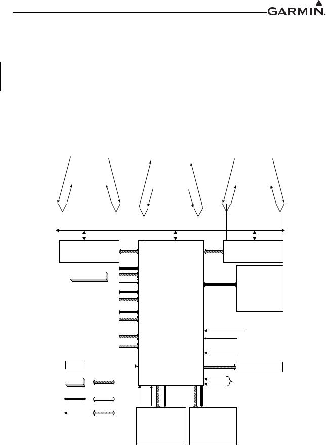
The GTS 8XX system is designed to use active interrogations of Mode S and Mode C transponders to provide Traffic Advisories (TA) to the pilot. Traffic is displayed on a multifunction display (MFD) via ARINC 429 and/or High Speed Data Bus (HSDB). An overview of the GTS 8XX system and its interfaces are shown in Figure 2-1.
2.2 Equipment Description
The GTS 8XX is a microprocessor-based Line Replaceable Unit (LRU) that uses active interrogations of Mode S and Mode C transponders to provide Traffic Advisories (TAs) to the pilot.
When properly configured, the GTS 8XX system will utilize passive surveillance to provide ADS-B In traffic. The GTS ADS-B In capability allows the unit to receive traffic data through its 1090 MHz Extended Squitter (1090 ES) receiver. Using the received ADS-B Out broadcasts, the system provides correlated information about target aircraft, including identification, speed, and direction. GPS and magnetic heading inputs to the GTS 8XX are required for ADS-B In to operate. Although ADS-B In relies on 1090ES ADS-B Out broadcasts from other aircraft, it is not necessary for the GTS-equipped aircraft to broadcast an ADS-B Out signal.
Aural alerts are provided to inform the crew of TAs. A top-mounted directional antenna is used to derive bearing of the intruder aircraft, which is displayed with relative altitude to own aircraft. Top antenna transmitted interrogations are directional, reducing the number of transponders that receive the interrogation, thus reducing potential garble on the 1090 MHz band. An optional bottom antenna transmits omni directional interrogations. A bottom directional antenna installation gives the benefit of intruder bearing visibility for targets that are shaded from the top directional antenna. Target bearing accuracy may be degraded on fixed gear aircraft with a bottom directional antenna.
2.3 Electrical Current Requirements
Table 2-1 shows current requirements for the GTS 8XX system.
Table 2-1 GTS 8XX System Current Requirements
LRU |
14V Current Draw |
28V Current Draw |
|||
Typical |
Maximum |
Typical |
Maximum |
||
|
|||||
GTS 800 |
2.2 A |
2.6 A |
1.1 A |
1.5 A |
|
|
|
|
|
|
|
GTS 820/850 |
2.7 A |
3.2 A |
1.3 A |
1.6 A |
|
|
|
|
|
|
|
GTS Processor |
3.5 A |
7.5 A |
1.7 A |
3.1 A |
|
|
|
|
|
|
|
190-01279-01 |
GTS 8XX Part 23 AML STC Maintenance Manual |
Rev. 2 |
Page 2-2 |
2.4 Interface Summary
The GTS 8XX system is designed as an open architecture system that uses ARINC 429, RS-232, and HSDB communications interfaces, as well as analog and discrete inputs and outputs. GTS 8XX interfaces include:
• |
Three RS-232 Inputs/Outputs |
• |
Alert Audio Output |
• |
Two RS-422 Input/Output |
• Ten Active Low Discrete Inputs |
|
• |
Twelve ARINC 429 Inputs/Outputs |
• Two Active High Discrete Inputs |
|
• |
Configuration Module |
• |
External Suppression Input/Output |
• |
Aircraft Power Input |
• |
Four Annunciator Outputs |
• |
Analog Radar Altimeter Input |
• |
HSDB Input/Output |
•26 VAC Heading Reference Input
|
|
|
|
|
|
|
Mode A/C |
|
|
|
|
||
|
|
|
|
|
|
|
Interrogations |
|
|
|
|||
|
|
|
|
|
Mode S Interrogations |
|
|
|
|||||
|
|
|
|
|
Broadcast Messages |
|
|
|
|||||
|
|
|
|
|
|
|
|
|
|
|
1 |
|
|
|
X |
|
|
|
|
|
|
|
|
0 |
|
||
|
|
|
|
|
|
|
|
|
0 |
||||
|
R |
|
|
|
|
|
|
|
|
3 |
|
||
|
z |
|
|
|
|
Mode A/C/S |
|
|
M |
||||
|
H |
|
|
|
|
|
|
z |
|||||
M |
|
|
|
|
Replies |
|
|
H |
|||||
|
|
|
|
|
|
|
R |
||||||
0 |
|
|
|
|
|
|
|
|
|
|
|
|
X |
3 |
|
|
|
|
|
Mode S Squitter |
|
1 |
|
|
|||
0 |
|
|
TX |
|
|
|
|
|
|||||
1 |
|
|
|
|
|
|
|
|
|
9 |
|
|
|
|
|
z |
|
|
|
|
|
|
|
|
0 |
|
|
|
H |
|
|
|
|
|
|
|
|
M |
|||
|
M |
|
|
|
|
|
|
|
|
H |
|||
0 |
|
|
|
|
|
|
|
|
|
z |
|||
9 |
|
|
|
|
|
|
|
|
|
TX |
|||
0 |
|
|
|
|
|
|
|
|
|
||||
1 |
|
|
|
|
|
|
|
|
|
|
|
|
|
|
|
|
Optional |
|
Bottom |
|
|||||||
|
|
|
|
Top |
|
|
|||||||
|
|
|
|
|
Antenna |
|
|||||||
|
|
|
Antenna |
|
|
||||||||
|
|
|
|
|
|
|
|
|
|
||||
|
|
|
|
|
|
|
|
|
|
|
|
|
|
|
|
|
|
|
|
|
|
|
|
|
|
|
|
|
|
|
|
|
|
|
|
|
|
|
|
|
|
|
|
|
|
Mode C Interrogations |
|
|
|
||||
|
|
|
|
Broadcast Messages |
|
|
|||||
|
|
|
|
Mode S Interrogations |
|
|
|||||
|
|
|
|
|
|
|
|
|
|
1 |
|
|
|
|
|
|
|
|
|
|
|
0 |
|
|
|
|
|
|
|
|
|
|
|
3 |
|
|
|
X |
|
|
|
|
|
|
|
0 |
|
|
|
|
|
|
|
|
|
|
H |
||
|
|
T |
|
|
Mode C Replies |
|
M |
||||
|
|
|
|
|
z |
||||||
|
z |
|
|
|
T |
||||||
|
H |
|
|
Mode S Replies |
|
X |
|||||
|
M |
|
|
|
|
|
|||||
0 |
|
|
Mode S Squitters |
|
1 |
|
|||||
3 |
|
X |
|
|
|
||||||
0 |
|
|
|
|
|
|
|
|
0 |
|
|
1 |
|
R |
|
|
|
|
|
|
|
9 |
|
|
|
|
|
|
|
|
|
|
|||
|
|
z |
|
|
|
|
|
|
|
0 |
|
|
|
H |
|
|
|
|
|
|
|
M |
|
|
|
M |
|
|
|
|
|
|
|
H |
|
|
0 |
|
|
|
Optional |
z |
|||||
|
9 |
|
|
|
R |
||||||
|
0 |
|
|
|
|
|
|
|
X |
||
|
|
1 |
Top |
|
Bottom |
|
|
||||
|
|
Directional |
Directional or |
|
|
||||||
|
|
|
Antenna |
Monopole |
|
|
|||||
|
|
|
|
|
|
Antenna |
|
|
|||
|
|
|
|
|
|
Suppression Bus |
|
||||
|
|
|
|
|
|
|
|||||
|
|
|
|
|
|
|
|||||
|
|
|
|
|
|
|
|
|
|
|
|
|
|
|
|
|
|
|
|
|
|
|
|
|
|
|
|
|
|
|
|
|
|
|
|
|
|
|
Mode A/C |
|
|
|
|
|
|
Interrogations |
|
|
|
|
|
|
Mode S Interrogations |
|
0 |
|
|
|
|
Broadcast Messages |
|
||
X |
|
|
|
|
|
1 |
|
|
|
|
|
3 |
|
R |
|
|
|
|
|
|
|
|
|
|
0 |
||
z |
|
|
|
|
|
M |
H |
|
|
|
|
|
H |
M |
|
|
Mode A/C/S |
|
z |
|
0 |
|
|
|
R |
||
3 |
|
|
|
|
|
X |
0 |
|
|
Replies |
|
|
|
1 |
|
|
|
|
||
|
TX |
Mode S Squitter |
1 |
|||
|
|
|
9 |
|||
z |
|
|
|
|
0 |
|
|
|
|
|
0 |
||
H |
|
|
|
|
||
|
|
|
|
|
M |
|
M |
|
|
|
|
|
H |
0 |
|
|
|
|
|
z |
9 |
|
|
|
|
|
T |
0 |
|
|
|
|
|
X |
1 |
|
|
|
|
|
|
Optional
Top
Bottom
Antenna
Antenna
Mode S Transponder
Compatible TX/RX interface required for power programming
|
Pressure Altitude* |
|
|
|
||||
|
Transponder |
|
|
|
||||
|
Serializer |
|
OR |
|||||
|
|
|
|
|
|
|
|
|
|
|
|
|
|
|
|
|
|
|
Magnetic Heading* |
|
OR |
|||||
|
(optional) |
|
|
|
||||
|
|
|
|
|
|
OR |
||
|
|
|
|
|
|
|||
|
GPS PVT* |
|
||||||
|
(optional) |
|
|
|
||||
|
|
|
|
|
|
|
|
|
|
|
|
|
|
|
|
|
|
|
Radar Altimeter |
|
OR |
|||||
|
(optional) |
|
||||||
|
|
|
|
|||||
|
|
|
|
|
|
|
|
|
|
|
|
|
|
|
TRFC Mute |
||
|
|
|
|
|
|
(Optional) |
||
|
|
|
|
|
|
|||
|
|
|
|
|
|
|
|
|
|
|
|
|
|
|
|
|
|
|
LRU |
|
Data |
|
|
|
||
Data Source |
ARINC 429 |
|
|
|
||||
|
Options |
|
|
|
|
|
|
|
|
HSDB |
|
RS-232 |
|
|
|
||
|
|
|
|
|
|
|
|
|
Discrete I/O |
|
Analog I/O |
|
|
|
|||
*The HSDB interface can perform all of the listed interface functions in place of separate analog/digital interfaces.
Mode S Transponder
(Optional Second Unit) Compatible TX/RX interface required for power programming
GTS TRAFFIC SYSTEM
GTS 800 TAS
GTS 820 TAS
GTS 825 TAS
GTS 850 TCAS I
GTS 855 TCAS I
OPR/SBY |
Self Test |
G950/G1000 System*
|
Pressure Altitude |
|||
|
Magnetic Heading |
|||
|
GPS PVT |
|||
|
Radio Altitude |
|||
|
Air /Gnd Status |
|||
|
Ldg Gear Position |
|||
|
Mode S TX/RX interface |
|||
|
Control/Display |
|||
Air/Gnd Status |
(Optional) |
|||
|
||||
Ldg Gear Position |
(Req’d for retractable ldg gear) |
|||
|
||||
|
|
|
||
Audio Inhibit |
High-Priority |
|
|
|
Audio Source |
|
|||
|
(e.g.,TAWS) |
|
||
Audio Output |
|
|
|
|
|
|
|
||
Audio Panel |
|
|||
|
|
|||
OPR/SBY |
|
|
|
|
External control inputs required |
||||
Self Test / |
||||
if Display Unit is only unit installed |
||||
Alt Filter |
|
|
|
|
Control/Display* |
Display Unit* |
|||
|
Unit |
|||
|
|
|
||
|
|
|
|
|
|
Color Display |
|
Color Display |
|
|
|
|
|
|
|
Knobs/Buttons |
|
|
|
|
Figure 2-1 GTS 8XX System Interface Diagram |
|
|
190-01279-01 |
GTS 8XX Part 23 AML STC Maintenance Manual |
Rev. 2 |
Page 2-3 |

2.5 Ground Plane
Ground plane definition varies with airframe type and aircraft model, as defined in Table 2-2. Refer to the periodic test and reconditioned resistance values corresponding to these ground plane definitions when performing the equipment bonding test per Section 4.3. Ensure that all GTS 8XX system antenna coaxial cables are disconnected during resistance checks.
Table 2-2 Ground Plane Definitions and Ground Path Resistance Requirements
|
|
|
Maximum Resistance Between |
|
|
Aircraft Type/Model |
Ground |
GTS 8XX Chassis and Ground |
Notes |
||
Reference |
Reference (mΩ) |
|
|
||
|
|
|
Periodic Test |
Reconditioned |
|
|
|
|
|
|
|
Metal airframe |
|
Nearby metallic |
10.0 |
2.5 |
|
|
structure |
|
|||
|
|
|
|
|
|
|
|
|
|
|
|
Tube airframe with fabric cover |
Nearby metallic |
10.0 |
2.5 |
|
|
structure |
|
||||
|
|
|
|
|
|
|
|
|
|
|
|
Composite VFR-only Models |
|
|
|
|
|
Diamond |
DA 40, DA 40F |
Instrument panel |
50.0 |
25.0 |
|
|
|
|
|
|
|
Composite IFR Models |
|
|
|
|
|
|
LC40-550FG, |
Nearby aluminum |
|
|
|
Cessna |
LC41-550FG, |
lightning ground |
10.0 |
5.0 |
|
|
LC42-550FG |
bar/strip |
|
|
|
|
|
|
|
|
|
|
|
Local grounded |
|
|
|
|
SR20, |
structure (such as |
|
|
|
Cirrus |
SR22, |
seat support |
10.0 |
5.0 |
|
|
SR22T |
structure, entry |
|
|
|
|
|
step) |
|
|
|
|
|
|
|
|
|
|
DA 40, |
Nearby structure |
|
|
|
|
lightning ground |
10.0 |
5.0 |
[1] |
|
|
DA 40F |
||||
Diamond |
tube |
|
|
|
|
|
|
|
|
||
|
|
|
|
|
|
|
DA 42, |
Nearby lightning |
10.0 |
5.0 |
|
|
DA 42 N-MG |
ground |
|
||
|
|
|
|
||
|
|
|
|
|
|
Notes:
[1]Diamond DA 40 and DA 40F with Diamond OSB 40-004/3 incorporated, or aircraft with similar factory-installed lightning protection supporting IFR operation.
190-01279-01 |
GTS 8XX Part 23 AML STC Maintenance Manual |
Rev. 2 |
Page 2-4 |
3 CONTROL AND OPERATION
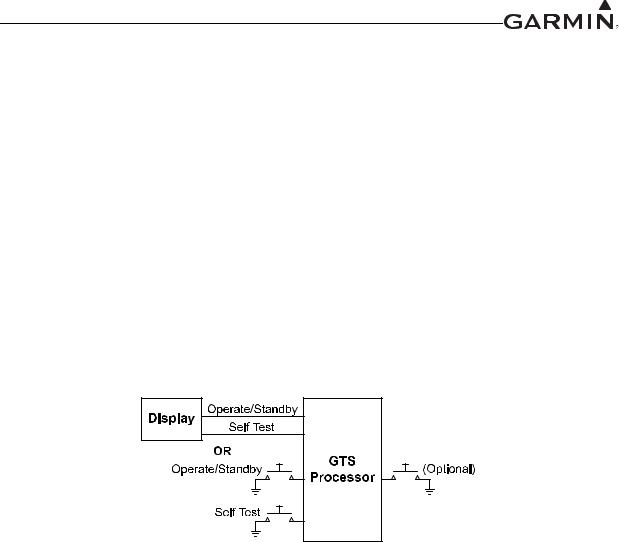
The GTS 8XX system includes functions that can be controlled via configured displays or external switches. Figure 3-1 summarizes GTS 8XX system control. Refer to display documentation for traffic system control details.
Operate/Standby
The Operate/Standby function toggles the GTS 8XX system between Operate and Standby modes. Operate/Standby may be controlled through a compatible display or external switch.
Self-Test
The GTS 8XX built-in self-test function may be controlled either through a compatible display or an external switch.
Traffic Mute (optional)
The optional Traffic Mute function mutes traffic audio alerts and is controlled by an external switch.
Traffic Mute
Figure 3-1 GTS 8XX Traffic System Controls
190-01279-01 |
GTS 8XX Part 23 AML STC Maintenance Manual |
Rev. 2 |
Page 3-1 |

4 INSTRUCTIONS FOR CONTINUED AIRWORTHINESS
4.1 |
Airworthiness Limitations .................................................................................................. |
4-2 |
|
4.2 |
Servicing Information ......................................................................................................... |
4-2 |
|
4.2.1 |
Periodic Maintenance................................................................................................................. |
4-2 |
|
4.2.2 |
Special Tools .............................................................................................................................. |
4-2 |
|
4.3 |
Maintenance Intervals......................................................................................................... |
4-3 |
|
This document is designed for use by the installing agency of the Garmin GTS 8XX Traffic System as Instructions for Continued Airworthiness in response to 14 CFR 23.1529 and 14 CFR 23 Appendix G. This ICA includes information required by the operator to adequately maintain the GTS 8XX system installed under the Approved Model List (AML) STC.
190-01279-01 |
GTS 8XX Part 23 AML STC Maintenance Manual |
Rev. 2 |
Page 4-1 |


4.3 Maintenance Intervals
Maintenance Item |
Interval |
|
Description/Procedure |
|
|
|
|
|
|
Visually inspect the GTS 8XX system antenna(s) for the following: |
|
|
|
• Environmental seal damage or decomposition |
|
|
|
• Cracks in the antenna body |
|
|
|
• Mounting structure damage or deformation |
|
|
|
• Corrosion on metallic structures |
|
|
|
If the antenna is not properly attached, or the antenna seal shows signs of damage or deterioration, complete |
|
|
|
the following procedure: |
|
|
|
1. Remove, clean, and reattach the antenna. |
|
Antenna visual inspection |
12 calendar months |
2. Complete the antenna electrical bonding test as described below. |
|
3. |
Reseal the antenna. |
||
|
|
If the antenna is damaged or cracked, remove and replace the antenna in accordance with Section 6 |
|
|
|
(antenna(s) installed under this STC), or the antenna installation data (antenna(s) not installed under this |
|
|
|
STC). After installing antenna, complete the antenna electrical bonding test described below (if applicable). |
|
|
|
If aircraft structure, at location of the antenna, is deformed or damaged, remove the antenna and repair |
|
|
|
aircraft structure in accordance with aircraft model-specific structural repair manual. After the aircraft repair |
|
|
|
is complete, perform the following: |
|
|
|
1. Clean and reattach the antenna. |
|
|
|
2. Complete the antenna electrical bonding test as described below (if applicable). |
|
|
|
3. |
Reseal the antenna. |
|
|
|
|
|
|
In the event of a suspected or actual lightning strike to the aircraft, the GTS 8XX system antenna(s) and |
|
|
|
antenna cable installation must be inspected. |
|
|
|
1. |
Inspect the antenna(s) and surrounding area for structural damage. |
|
|
|
a. If the antenna is damaged, replace the antenna in accordance with Section 6. |
|
|
|
b. If the aircraft structure supporting the antenna installation is deformed or damaged, |
Antenna visual inspection - |
Suspected or actual |
|
remove the antenna and repair in accordance with procedures detailed in the aircraft |
|
model-specific structural repair manual. When repair is complete, continue with the |
||
suspected lightning strike |
lightning strike |
|
|
|
following steps. |
||
|
|
|
|
|
|
2. Inspect the antenna and coaxial cable connector ends for damage. If any damage is found on any |
|
|
|
|
antenna or coaxial cable connector, replace the antenna(s) or coaxial cable(s) in accordance with |
|
|
|
Section 6. |
|
|
3. Ensure that the coaxial cable connectors are securely attached to the antenna connectors. |
|
|
|
4. |
Perform the GTS 8XX system checkout procedure in accordance with Section 5. |
|
|
|
|
190-01279-01 |
GTS 8XX Part 23 AML STC Maintenance Manual |
Rev. 2 |
Page 4-3 |

|
|
|
|
|
|
|
|
|
|
|
|
|
|
|
|
|
|
Maintenance Item |
Interval |
|
Description/Procedure |
|
|
|
|
|
|
||
Antenna electrical bonding test |
|
An electrical bonding test must be performed on all GTS 8XX system antennas. The test procedure is: |
|
||
|
1. Gain access to the antenna. |
|
|||
(Not applicable to composite |
|
2. |
Disconnect the coaxial cable connector(s) from the antenna. |
|
|
VFR-only models) |
|
3. |
Measure the resistance between the antenna coaxial connector body and a nearby exposed portion |
|
|
|
|
|
|||
|
Every 2000 flight |
|
of aircraft metallic structure (e.g., exposed rivet on fuselage stringer). |
|
|
|
4. |
Verify the resistance is less than or equal to 10 mΩ. |
|
||
|
hours or ten years, |
|
|||
|
5. |
Reconnect the antenna connector(s). |
|
||
|
whichever is first |
|
|||
|
In the event of bonding test failure, perform the following procedure: |
|
|||
|
|
|
|||
|
|
1. Remove the antenna, clean, and re-install in accordance with Section 6. |
|
||
|
|
2. |
Measure the resistance between the antenna coaxial connector body and a nearby exposed portion |
|
|
|
|
|
of aircraft structure (e.g., exposed rivet on fuselage stringer). |
|
|
|
|
3. Verify the resistance is less than or equal to 2.5 mΩ. |
|
||
|
|
|
|
|
|
|
|
1. |
Disconnect the coaxial cable connector(s) from the GTS 8XX. |
|
|
|
|
2. |
Disconnect P8001, P8002, and P8003 connectors from the GTS 8XX. |
|
|
|
Following removal |
3. |
Measure the DC resistance between the GTS 8XX chassis and the aircraft ground, as defined in |
|
|
|
|
Table 2-2. Verify the resistance is less than or equal to the appropriate periodic test resistance value |
|
||
|
and replacement of |
|
|
||
|
|
listed in Table 2-2. |
|
||
|
the GTS 8XX install |
|
|
||
|
In the event of bonding test failure, perform the following procedure: |
|
|||
|
rack or bonding |
|
|||
Equipment electrical bonding |
components |
1. |
Remove GTS 8XX and install rack from the aircraft per instructions in Section 6. |
|
|
|
2. |
Ensure that the GTS 8XX and install rack are clean and free of dirt and debris. |
|
||
test |
AND |
|
|||
3. |
Ensure that all ground path components are in good condition and properly connected and attached |
|
|||
|
|
||||
|
Every 2000 flight |
|
to the aircraft. |
|
|
|
4. |
Re-install the GTS 8XX and install rack in accordance with Section 6. |
|
||
|
hours or ten years, |
|
|||
|
5. |
Measure the resistance between the GTS 8XX chassis and the aircraft ground, |
|
||
|
whichever is first |
|
|||
|
|
as defined in Table 2-2. |
|
||
|
|
|
|
||
|
|
6. |
Verify the resistance is less than or equal to the appropriate reconditioned resistance value listed in |
|
|
|
|
|
Table 2-2. |
|
|
|
|
|
|
||
Equipment removal and |
On condition |
Remove and replace the GTS 8XX and/or GTS 8XX system antenna. |
|
||
replacement |
See Section 6 for equipment removal and re-installation instructions. |
|
|||
|
|
||||
|
|
|
|
|
|
190-01279-01 |
GTS 8XX Part 23 AML STC Maintenance Manual |
Rev. 2 |
Page 4-4 |
|
|
|
|
|
|
|
|
|
|
|
|
|
|
|
Maintenance Item |
Interval |
Description/Procedure |
|
|
|
|
|
|
|
|
|
In the event of a suspected or actual lightning strike to the aircraft, the bonding components for the |
|
|
Equipment bonding visual |
Suspected or |
GTS 8XX: bonding straps and associated hardware (if applicable) must be inspected. If any damage is |
|
|
inspection – suspected |
actual lightning |
found, the damaged components must be replaced in accordance with specifications and procedures |
|
|
lightning strike |
strike |
shown in Appendix B. If any bonding components are replaced, complete the equipment electrical |
|
|
|
|
bonding test as described above. |
|
|
|
|
|
|
|
|
|
Conduct a visual inspection of the GTS 8XX installation in accordance with 14 CFR 43 Maintenance, |
|
|
|
|
Preventative Maintenance, Rebuilding and Alteration, Appendix D. If the equipment fails the visual |
|
|
|
|
inspection, complete the following procedure: |
|
|
Equipment visual inspection |
12 calendar months |
1. Correct improper installations and ensure that all mounting racks and fasteners are secure. |
|
|
2. Correct improper wire routing and ensure that the wire harness is securely mounted. Replace the |
|
|||
|
|
|
||
|
|
install rack or any wiring, bonding, or shielding component with obvious defects. |
|
|
|
|
3. If the install rack or any bonding components are replaced, complete the equipment electrical |
|
|
|
|
bonding test as described above. |
|
|
|
|
|
|
|
190-01279-01 |
GTS 8XX Part 23 AML STC Maintenance Manual |
Rev. 2 |
Page 4-5 |
 Loading...