


 Loading...
System Maintenance Manual
GTN 6XX/7XX Part 23 AML STC
Contains Instructions for Continued Airworthiness for STC SA02019SE-D
Aircraft Make, Model, Registration Number, and Serial
Number along with the applicable STC configuration information must be completed in Appendix A and saved with aircraft permanent records.
190-01007-A1 |
November 2014 |
Revision 7 |

© 2011-2014
Garmin International, Inc., or its subsidiaries All Rights Reserved
Except as expressly provided herein, no part of this manual may be reproduced, copied, transmitted, disseminated, downloaded or stored in any storage medium, for any purpose without the express prior written consent of Garmin. Garmin hereby grants permission to download a single copy of this manual and of any revision to this manual onto a hard drive or other electronic storage medium to be viewed and to print one copy of this manual or of any revision hereto, provided that such electronic or printed copy of this manual or revision must contain the complete text of this copyright notice and provided further that any unauthorized commercial distribution of this manual or any revision hereto is strictly prohibited.
Adobe® is a registered trademark of Adobe Systems Incorporated. All rights reserved.
© 2014 The Bluetooth® word mark and logos are registered trademarks owned by Bluetooth SIG, Inc. and any use of such marks by Garmin is under license. Other trademarks and trade names are those of
their respective owners.
© 2014 Sirius XM Radio Inc. Sirius, XM and all related marks and logos are trademarks of Sirius XM Radio Inc. All other marks and logos are property of their respective owners. All rights reserved.
Garmin®, FliteCharts®, and SafeTaxi® are registered trademarks of Garmin International or its subsidiaries. Connext™, Garmin Pilot™, GDU™, GTN™, and Telligence™ are trademarks of Garmin International or its subsidiaries. These trademarks may not be used without the express permission of Garmin.
At Garmin, we value your opinion.
For comments about this guide, please e-mail: Techpubs.Salem@garmin.com.
Garmin International Inc. 1200 E. 151st Street Olathe, Kansas 66062 USA Telephone: (913) 397-8200 www.garmin.com
Aviation Dealer Technical Support Telephone (Toll Free): (888) 606-5482 Fax: (913) 397-0868
Fax (Toll Free): (800) 801-4670 E-mail: orders@garmin.com avionics@garmin.com warranty@garmin.com
Garmin AT, Inc.
2345 Turner Rd. SE
Salem, OR 97302 USA
Telephone: (503) 581-8101
Fax: (503) 364-2138
E-mail: support.salem@garmin.com
190-01007-A1 |
System Maintenance Manual GTN 6XX/7XX Part 23 AML STC |
Rev. 7 |
Page A |
Garmin (Europe) Ltd.
Liberty House, Hounsdown Business Park
Southampton, Hampshire SO40 9LR U.K.
Phone: +44 (0) 23 8052 4000
Fax: +44 (0) 23 8052 4004
Aviation Support +44 (0) 87 0850 1243
|
|
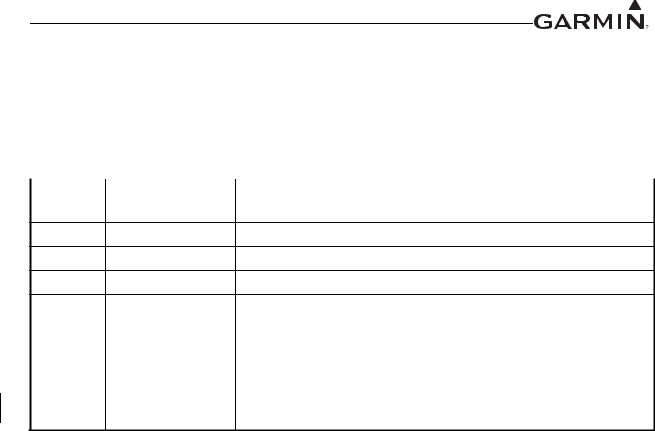
RECORD OF REVISIONS |
|
|
|
Revision |
Revision Date |
Description |
1 |
03/04/2011 |
Initial Release |
201/18/2012 Added instructions for NAV antenna cable splitter and diplexer.
311/19/12 Reorganized to add maintenance instructions.
412/13/12 Removed ASR material and other minor edits.
|
|
Revised to incorporate changes associated with GTN main software |
|
5 |
3/25/2013 |
version 4.10, COM software version 2.11, and GMA software version |
|
|
|
3.05. |
|
|
|
|
|
6 |
10/22/13 |
Revised to incorporate changes associated with GTN main software |
|
version 5.00. |
|||
|
|
||
|
|
|
|
7 |
11/25/14 |
Revised to incorporate changes associated with GTN |
|
main software version 5.13. |
|||
|
|
DOCUMENT PAGINATION
Section |
Pagination |
|
|
Table of Contents |
ii through v |
|
|
Section 1 |
1-1 through 1-4 |
|
|
Section 2 |
2-1 through 2-5 |
|
|
Section 3 |
3-1 through 3-19 |
|
|
Section 4 |
4-1 through 4-10 |
|
|
Section 5 |
5-1 through 5-22 |
|
|
Section 6 |
6-1 through 6-28 |
|
|
Section 7 |
7-1 through 7-24 |
|
|
Section 8 |
8-1 through 8-1 |
|
|
Appendix A |
A-1 through A-35 |
|
|
190-01007-A1 |
System Maintenance Manual GTN 6XX/7XX Part 23 AML STC |
|
Rev. 7 |
Page B |
|
INFORMATION SUBJECT TO EXPORT CONTROL LAWS
This document may contain information which is subject to the Export Administration Regulations (“EAR”) issued by the United States Department of Commerce (15 Code of Federal Regulations (CFR), Chapter VII, Subchapter C) and which may not be exported, released, or disclosed to foreign nationals inside or outside of the United States without first obtaining an export license. A violation of the EAR may be subject to a penalty of up to 10 years imprisonment and a fine of up to $1,000,000 under Section 2410 of the Export Administration Act of 1979. Include this notice with any reproduced portion of this document.
This information in this document is subject to change without notice. Visit the Garmin web site (www.garmin.com) for current updates and supplemental information concerning the operation of Garmin products.
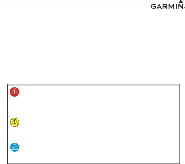
DEFINITIONS OF WARNINGS, CAUTIONS, AND NOTES
WARNING
Warnings are used to bring to the installer’s immediate attention that not only damage to the equipment but personal injury may occur if the instruction is disregarded.
CAUTION
Cautions are used to alert the individual that damage to equipment may result if the procedural step is not followed to the letter.
NOTE
Notes are used to expand and explain the preceding step and provide further understanding of the reason for the particular operation.
190-01007-A1 |
System Maintenance Manual GTN 6XX/7XX Part 23 AML STC |
|
Rev. 7 |
Page i |
|

TABLE OF CONTENTS
1 |
INTRODUCTION.............................................................................................................................. |
|
1-1 |
|
|
|
1.1 |
Content, Scope and Purpose....................................................................................................... |
1-1 |
|
|
|
1.2 |
Organization ............................................................................................................................... |
|
1-1 |
|
|
1.3 |
Definitions and Abbreviations ................................................................................................... |
1-2 |
|
|
|
1.4 |
Publications ................................................................................................................................ |
|
1-3 |
|
|
1.5 |
Distribution................................................................................................................................. |
|
1-4 |
|
2 |
SYSTEM DESCRIPTION................................................................................................................. |
|
2-1 |
||
|
2.1 |
Equipment Descriptions ............................................................................................................. |
|
2-1 |
|
|
2.2 |
Backplate Connectors................................................................................................................. |
|
2-2 |
|
|
2.3 |
GTN Optional Interfaces............................................................................................................ |
|
2-4 |
|
|
2.4 |
GTN Block Diagram .................................................................................................................. |
|
2-5 |
|
3 GTN CONTROL AND OPERATION............................................................................................. |
3-1 |
||||
|
3.1 |
GTN Controls............................................................................................................................. |
|
3-1 |
|
|
3.2 |
GTN Normal Mode Overview ................................................................................................... |
3-1 |
||
|
3.3 |
Software Loading ....................................................................................................................... |
|
3-2 |
|
|
3.4 |
GTN Configuration Mode Overview ......................................................................................... |
3-6 |
||
|
3.5 |
Database Updates ..................................................................................................................... |
|
3-19 |
|
4 INSTRUCTIONS FOR CONTINUED AIRWORTHINESS......................................................... |
4-1 |
|
|||
|
4.1 |
Airworthiness Limitations.......................................................................................................... |
|
4-1 |
|
|
4.2 |
Servicing Information ................................................................................................................ |
|
4-1 |
|
|
4.3 |
Maintenance Intervals ................................................................................................................ |
|
4-2 |
|
|
4.4 |
Visual Inspection........................................................................................................................ |
|
4-3 |
|
|
4.5 |
Electrical Bonding Test.............................................................................................................. |
|
4-4 |
|
|
4.6 |
Transient Voltage Suppressor (TVS) (If Installed) .................................................................... |
4-8 |
||
|
4.7 |
GPS/SBAS Antenna Cable Overbraid Inspection (If Installed)............................................... |
4-10 |
||
|
4.8 |
WXR HSDB Cable Overbraid Inspection (If Installed)........................................................... |
4-10 |
||
5 |
TROUBLESHOOTING .................................................................................................................... |
|
5-1 |
|
|
|
5.1 |
GTN General Troubleshooting................................................................................................... |
5-1 |
||
|
5.2 |
GTN Failure Annunciations ....................................................................................................... |
5-5 |
||
|
5.3 |
GTN System Messages .............................................................................................................. |
|
5-6 |
|
|
5.4 |
Flight Stream Troubleshooting................................................................................................. |
5-20 |
||
|
5.5 |
GMA 35 Troubleshooting ........................................................................................................ |
|
5-21 |
|
|
5.6 |
GMA 35 Failure Annunciations............................................................................................... |
5-21 |
||
|
5.7 |
GMA 35 System Messages |
...................................................................................................... |
5-22 |
|
6 EQUIPMENT REMOVAL AND REINSTALLATION ................................................................ |
6-1 |
||||
|
6.1 |
GTN............................................................................................................................................ |
|
6-1 |
|
|
6.2 |
GMA 35...................................................................................................................................... |
|
6-5 |
|
|
6.3 |
Data Card.................................................................................................................................... |
|
6-7 |
|
|
6.4 |
Flight Stream 210 ....................................................................................................................... |
|
6-8 |
|
|
6.5 |
NAV Antenna Cable Diplexer ................................................................................................... |
6-9 |
|
|
|
6.6 |
NAV Antenna Cable Splitter.................................................................................................... |
6-10 |
|
|
|
6.7 |
Configuration Module (P1001 Only) ....................................................................................... |
6-11 |
||
|
6.8 |
GTN Fan................................................................................................................................... |
|
6-14 |
|
|
6.9 |
TVS and Fuse (Nonmetallic Aircraft Only)............................................................................. |
6-17 |
||
|
6.10 |
GPS/SBAS Antenna Cable Overbraid ..................................................................................... |
6-21 |
||
|
6.11 |
WXR HSDB Cable Overbraid ................................................................................................. |
6-23 |
|
|
|
6.12 |
Instrument Panel Bonding Strap .............................................................................................. |
6-26 |
|
|
|
6.13 |
Flight Stream 210 Bonding Strap............................................................................................. |
6-27 |
|
|
|
|
|
|||
190-01007-A1 |
System Maintenance Manual GTN 6XX/7XX Part 23 AML STC |
||||
Rev. 7 |
|
|
Page ii |
||

TABLE OF CONTENTS CONTINUED
7 |
EQUIPMENT CONFIGURATION AND TESTING..................................................................... |
7-1 |
|
|
7.1 |
GTN 6XX/7XX .......................................................................................................................... |
7-1 |
|
7.2 |
GMA 35...................................................................................................................................... |
7-6 |
|
7.3 |
Configuration Module .............................................................................................................. |
7-10 |
|
7.4 |
Interfaced Equipment ............................................................................................................... |
7-10 |
|
7.5 |
Enabled Features ...................................................................................................................... |
7-23 |
8 |
SYSTEM RETURN TO SERVICE PROCEDURE........................................................................ |
8-1 |
|
|
8.1 |
Maintenance Records ................................................................................................................. |
8-1 |
APPENDIX A AIRCRAFT SPECIFIC INFORMATION ................................................................. |
A-1 |
||
190-01007-A1 |
System Maintenance Manual GTN 6XX/7XX Part 23 AML STC |
|
Rev. 7 |
Page iii |
|

LIST OF FIGURES
Figure 2-1. GMA 35 Connector Layout Detail - Rear View ..................................................................... |
2-2 |
Figure 2-2. GTN 650 Connector Layout Detail - Rear View .................................................................... |
2-3 |
Figure 2-3. GTN 750 Connector Layout Detail - Rear View .................................................................... |
2-3 |
Figure 2-4. GTN System Interface Diagram ............................................................................................. |
2-5 |
Figure 3-1. GTN 6XX Normal Mode Screen ............................................................................................ |
3-1 |
Figure 3-2. GTN 7XX Normal Mode Screen ............................................................................................ |
3-1 |
Figure 3-3. GTN Software Updater ........................................................................................................... |
3-2 |
Figure 3-4. System and Software Version ................................................................................................. |
3-3 |
Figure 3-5. GTN Software Loader Card Formatting ................................................................................. |
3-3 |
Figure 3-6. Update Progress Window ....................................................................................................... |
3-4 |
Figure 3-7. Update Completion ................................................................................................................. |
3-4 |
Figure 3-8. GTN 6XX and GTN 7XX Configuration Mode Pages ........................................................... |
3-6 |
Figure 3-9. GTN 7XX Updates Page ......................................................................................................... |
3-7 |
Figure 3-10. System Information Page ...................................................................................................... |
3-8 |
Figure 3-11. GTN 7XX Setup Pages ......................................................................................................... |
3-9 |
Figure 3-12. GTN 7XX Options Pages .................................................................................................... |
3-11 |
Figure 3-13. GTN 7XX TAWS Configuration Page ............................................................................... |
3-12 |
Figure 3-14. Chart Configuration Page ................................................................................................... |
3-13 |
Figure 3-15. COM Transmit Power Configuration Page ......................................................................... |
3-14 |
Figure 3-16. Weather Radar Page ............................................................................................................ |
3-15 |
Figure 3-17. GTN 6XX and 7XX Diagnostics Pages .............................................................................. |
3-17 |
Figure 4-1. TVS Assembly Check ............................................................................................................. |
4-9 |
Figure 5-1. Failure Screen ......................................................................................................................... |
5-5 |
Figure 5-2. GMA 35 Failure Annunciation ............................................................................................. |
5-21 |
Figure 6-1. GTN 7XX Mounting Rack Assembly ..................................................................................... |
6-2 |
Figure 6-2. GTN 6XX Mounting Rack Assembly ..................................................................................... |
6-3 |
Figure 6-3. GMA 35 Mounting Rack Assembly Overview ...................................................................... |
6-6 |
Figure 6-4. Flight Stream Assembly Overview ......................................................................................... |
6-8 |
Figure 6-5. Backshell Assembly (Potted Configuration Module) ........................................................... |
6-12 |
Figure 6-6. Backshell Assembly (Configuration Module with Spacer) .................................................. |
6-13 |
Figure 6-7. Fan/Backplate Orientation (GTN 7XX) ................................................................................ |
6-14 |
Figure 6-8. Fan Wiring Replacement ...................................................................................................... |
6-16 |
Figure 6-9. TVS/Fuse Replacement (TVS1/F1) ...................................................................................... |
6-18 |
Figure 6-10. Detail of TVS Pin Assembly ............................................................................................... |
6-19 |
Figure 6-11. TVS2 Assembly .................................................................................................................. |
6-20 |
Figure 6-12. GPS/SBAS Antenna Cable Overbraid ................................................................................ |
6-22 |
Figure 6-13. WXR HSDB Cable Overbraid Details ................................................................................ |
6-24 |
Figure 6-14. Instrument Panel Bonding ................................................................................................... |
6-26 |
Figure 6-15. Flight Stream Bonding ........................................................................................................ |
6-28 |
Figure 7-1. Audio Panel Page .................................................................................................................... |
7-6 |
Figure 7-2. Main Indicator (Analog) Configuration Page ....................................................................... |
7-10 |
Figure 7-3. VOR/LOC/GS Configuration Page ....................................................................................... |
7-11 |
Figure 7-4. XPDR1 Configuration Page .................................................................................................. |
7-18 |
Figure 7-5. Audio Configuration Page .................................................................................................... |
7-23 |
Figure 7-6. TAWS Configuration Page ................................................................................................... |
7-23 |
190-01007-A1 |
System Maintenance Manual GTN 6XX/7XX Part 23 AML STC |
|
Rev. 7 |
Page iv |
|

LIST OF TABLES
Table 3-1. GTN Database Summary ....................................................................................................... |
3-19 |
Table 4-1. Periodic Maintenance ............................................................................................................... |
4-2 |
Table 5-1. GTN Troubleshooting Guide ................................................................................................... |
5-1 |
Table 5-2. Alert Text Troubleshooting Guide ........................................................................................... |
5-6 |
Table 5-3. COM Alert Troubleshooting Guide ......................................................................................... |
5-9 |
Table 5-4. GPS/SBAS Alert Troubleshooting Guide .............................................................................. |
5-11 |
Table 5-5. VLOC/GS Alert Troubleshooting Guide ............................................................................... |
5-12 |
Table 5-6. Remote Transponder Alert Troubleshooting Guide ............................................................... |
5-13 |
Table 5-7. GAD 42 Alert Troubleshooting Guide ................................................................................... |
5-14 |
Table 5-8. Traffic Alert Troubleshooting Guide ..................................................................................... |
5-14 |
Table 5-9. Datalink Alert Troubleshooting Guide ................................................................................... |
5-15 |
Table 5-10. Weather Radar Alert Troubleshooting Guide ...................................................................... |
5-17 |
Table 5-11. TAWS Alert Troubleshooting Guide ................................................................................... |
5-18 |
Table 5-12. Third-Party Sensor Alert Troubleshooting Guide ................................................................ |
5-19 |
Table 5-13. Flight Stream Troubleshooting ............................................................................................. |
5-20 |
Table 5-14. GMA 35 Troubleshooting .................................................................................................... |
5-21 |
Table 5-15. Remote Audio Panel Alert Troubleshooting Guide ............................................................. |
5-22 |
Table 6-1. Self Test Values ....................................................................................................................... |
6-4 |
Table 6-2. Configuration Module Wire Color Reference Chart .............................................................. |
6-11 |
Table 6-3. Configuration Module Kit 011-00979-03 (P1001) ................................................................ |
6-12 |
Table 6-4. Configuration Module Kit 011-00979-00 (P1001) ................................................................ |
6-13 |
Table 6-5. Fan Kit .................................................................................................................................... |
6-15 |
Table 6-6. Fan Cable Wire Color Reference Chart ................................................................................. |
6-15 |
Table 6-7. Instrument Panel Bonding Hardware ..................................................................................... |
6-26 |
Table 6-8. Flight Stream Bonding Hardware .......................................................................................... |
6-28 |
Table 7-1. Configuration and Checkout Procedures .................................................................................. |
7-2 |
190-01007-A1 |
System Maintenance Manual GTN 6XX/7XX Part 23 AML STC |
|
Rev. 7 |
Page v |
|

1 INTRODUCTION
1.1 Content, Scope and Purpose
This document provides Instructions for Continued Airworthiness (ICA) for the GTN 6XX/7XX and GMA 35 as installed under STC SA02019SE-D. This document satisfies the requirements for continued airworthiness as defined by 14 CFR Part 23.1529 and 14 CFR Part 23 Appendix G. Information in this document is required to maintain the continued airworthiness of the GTN 6XX/7XX, GMA 35, and Flight Stream 210.
1.2 Organization
The following outline briefly describes the organization of this manual:
Section 2: System Description
Provides a description of the equipment installed by STC SA02019SE-D. An overview of the GTN and GMA 35 system interface is also provided.
Section 3: GTN Control and Operation
Presents basic control and operation information specifically tailored to maintenance practices. Basic GTN Configuration Mode operation is also described as well as loading of software.
Section 4: Instructions for Continued Airworthiness
This section provides maintenance instructions for continued airworthiness of the GTN and GMA 35 systems.
Section 5: Troubleshooting
This section provides troubleshooting information to aid in diagnosing and resolving potential problems with the GTN and GMA 35 equipment.
Section 6: Equipment Removal and Reinstallation
This section provides instructions for the removal and reinstallation of the GTN and GMA 35 equipment.
Section 7: Equipment Configuration and Testing
This section provides instructions for the configuration and testing of the GTN and GMA 35 equipment.
Section 8: System Return to Service Procedure
This section specifies return-to-service procedures to be performed upon completion of maintenance of the GTN and GMA 35 equipment.
190-01007-A1 |
System Maintenance Manual GTN 6XX/7XX Part 23 AML STC |
|
Rev. 7 |
Page 1-1 |
|

1.3 Definitions and Abbreviations
The following terminology is used within this document:
AC: Alternating Current
ADS-B: Automatic Dependent Surveillance Broadcast AGC: Automatic Gain Control
AGCS: Automatic Ground Clutter Suppression AHRS: Altitude and Heading Reference System AML: Approved Model List
BIT: Built-In Test
CDI: Course Deviation Indicator
CFR: Code of Federal Regulations COM: Communications
CRG: Cockpit Reference Guide CSA: Conflict Situational Awareness DME: Distance Measuring Equipment
EFIS: Electronic Flight Instrument System EHSI: Electronic Horizontal Situation Indicator FIS-B: Flight Information Services Broadcast FPGA: Field-Programmable Gate Array
G/S: Glideslope
GAD: Garmin Interface Adapter GDL: Garmin Datalink
GMA: Garmin Audio Panel GNS: Garmin Navigation System GPS: Global Position System GSR: Garmin Services
GTN: Garmin Touch Navigator
GWX: Garmin Weather Radar
HSDB: High-Speed Data Bus
ICA: Instructions for Continued Airworthiness ICS: Intercom System
IFR: Instrument Flight Rules ILS: Instrument Landing System IRU: Inertial Reference Unit LED: Light Emitting Diode LOC: Localizer
LOI: Loss of Integrity LRU: Line Replaceable Unit MHz: Mega-Hertz
NAV: Navigation
OBS: Omni Bearing Selector PA: Passenger Address
190-01007-A1 |
System Maintenance Manual GTN 6XX/7XX Part 23 AML STC |
|
Rev. 7 |
Page 1-2 |
|
PED: Portable Electronic Device
PTC: Push-to-Command
PTT: Push-to-Talk
PVT: Position, Velocity, Time
R/T: Radar Transceiver
RF: Radio Frequency
RMI: Radio Magnetic Indicator
RX: Receive
SBAS: Satellite Based Augmentation System
SDI: Source/Destination Identifiers
SSM: Sign/Status Matrix
STC: Supplemental Type Certificate
TAS: Traffic Advisory System
TCAS: Traffic Collision Avoidance System
TAWS: Terrain Awareness System
TCAD: Traffic Collision Avoidance Device
TIS: Traffic Information Service
TSO: Technical Standard Order
TVS: Transient Voltage Suppressors
TX: Transmit
UTC: Coordinated Universal Time
VDC: Volts Direct Current
VFR: Visual Flight Rules
VHF: Very High Frequency
VOR: VHF Omni-directional Range
WAAS: Wide Area Augmentation System
WXR: Weather Radar
XPDR: Transponder
1.4 Publications
Part Number |
Garmin Document |
|
005-00533-C0 |
Master Drawing List, GTN 6XX/7XX |
|
|
|
|
005-00533-C1 |
GTN 6XX/7XX Equipment List |
|
|
|
|
190-01007-A2 |
Supplemental Airplane Flight Manual for the Garmin GTN 6XX/7XX |
|
GPS/SBAS Navigation System |
||
|
||
|
|
|
190-01007-A5 |
Supplemental Airplane Flight Manual for Garmin GTN 6XX/7XX GPS/ |
|
SBAS Navigation System (GPS Functions Not Approved for IFR |
||
|
Navigation) |
|
|
|
|
190-01007-A3 |
GTN 6XX/7XX AML STC Installation Manual |
|
|
|
|
190-01007-E1 |
GTN 6XX/7XX Installation Checklist |
|
|
|
190-01007-A1 |
System Maintenance Manual GTN 6XX/7XX Part 23 AML STC |
|
Rev. 7 |
Page 1-3 |
|

1.5 Distribution
This document is required for maintaining the continued airworthiness of the aircraft. When this document is revised, every page will be revised to indicate the current revision level. Garmin Dealers may obtain the latest revision of this document on the Garmin Dealer Resource Center website.
Owner/operators may obtain the latest revision of this document from www.flyGarmin.com or by contacting a Garmin dealer. Other contacts include Garmin Product Support at 913-397-8200 (toll free 866-739-5687) or using around the world contact information on www.flyGarmin.com.
A Garmin Service Bulletin describing the revision to this document will be sent to Garmin dealers if the revision is determined to be significant.
190-01007-A1 |
System Maintenance Manual GTN 6XX/7XX Part 23 AML STC |
Rev. 7 |
Page 1-4 |

2 SYSTEM DESCRIPTION
2.1 Equipment Descriptions
2.1.1GTN 6XX/7XX Navigators and GMA 35
The GTN SBAS navigators are a family of aviation panel mounted retro-fit products. The following sections will describe the available functions for each unit in the GTN 6XX/7XX navigators.
2.1.1.1GTN 6XX
The GTN 6XX SBAS navigators are a family of panel-mounted GPS/NAV/COM navigators.
The GTN 6XX units include the GTN 625, GTN 635, and GTN 650. They are 6.25" wide and 2.65" tall. The GTN 6XX features a 600 by 266 pixel color LCD touchscreen. The GTN 625 is a GPS/SBAS unit that meets the requirements of Technical Standard Order TSO-C146c and may be approved for IFR en route, terminal, oceanic, non-precision, and precision approach operations when installed in accordance with the instructions in the manuals referenced in the GTN AML STC. The
GTN 635 includes all of the features of the GTN 625 in addition to an airborne VHF communications transceiver. The GTN 650 includes all of the features of the GTN 625 in addition to an airborne VHF communications transceiver and airborne VOR/localizer (LOC) and glideslope (G/S) receivers.
2.1.1.2GTN 7XX
The GTN 7XX SBAS navigators are a family of GPS/NAV/COM aviation panel-mounted products. The GTN 7XX units include the GTN 725 and GTN 750. The GTN 7XX units are 6.25" wide and 6.00" tall. They feature a 600 by 708 pixel color LCD touchscreen. The GTN 725 is a GPS/SBAS unit that meets the requirements of Technical Standard Order TSO-C146c and may be approved for IFR en route, terminal, oceanic, non-precision, and precision approach operations when installed in accordance with the instructions in the manuals referenced in the GTN AML STC. The GTN 750 includes all of the features of the GTN 725 in addition to an airborne VHF communications transceiver and airborne VOR/localizer (LOC) and glideslope (G/S) receivers. The GTN 725 and 750 also have the ability to remotely control GMA 35 audio panel functions.
2.1.1.3GMA 35 Audio Panel
The GMA 35 audio panel is both a marker beacon receiver and an audio panel with 6-place intercom that interfaces to the communications and navigation radios, headsets, microphones, and speakers. The GMA 35 is remote-mounted and relies upon the GTN 725 or GTN 750 to control and display the audio functions.
The GMA 35 interfaces to the GTN 7XX through RS-232 for control and display of audio panel functions. Additionally, the GMA 35 includes a six-position intercom system (ICS) with electronic cabin noise deemphasis, two stereo music inputs, and independent pilot, copilot, and passenger volume controls. The intercom provides three selectable isolation modes. A pilot-selectable cabin speaker output can be used to listen to the selected aircraft radios or to broadcast PA announcements.
2.1.1.4Flight Stream 210
The Flight Stream 210 brings Bluetooth® connectivity to the cockpit, allowing portable electronics to stream data to and from the installed avionics.
The Flight Stream 210 interfaces to the GTN 6XX/7XX (Flight Stream supports connection to one navigator at a time) through RS-232 for attitude information, flight plan information, and GPS PVT and displays that information on a portable electronic device (PED). The Flight Stream may interface to the GDL 88 through RS-422 and the GDL 69 through RS-232 as well.
190-01007-A1 |
System Maintenance Manual GTN 6XX/7XX Part 23 AML STC |
Rev. 7 |
Page 2-1 |
2.1.2NAV Antenna Cable Splitter
The navigation antenna cable splitter (Garmin P/N 013-00112-00) is used for installations involving dual VHF navigation capable GTNs or a single VHF navigation capable GTN installation with a second non-Garmin aviation unit.
2.1.3NAV Antenna Cable Diplexer
The GTN 650/750 navigation units have a single navigation antenna port and thus require a composite signal for those installations which include separate VOR/LOC and G/S antennas. The navigation diplexer (Comant diplexer VOR/GS, Model CI-507) is used for these installations.
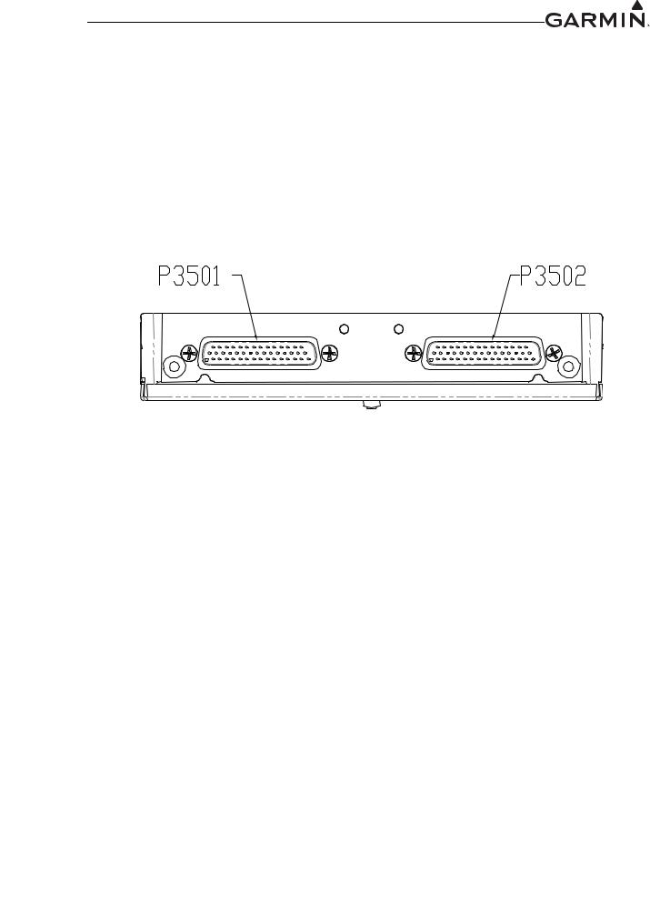
2.2 Backplate Connectors
Figure 2-1. GMA 35 Connector Layout Detail - Rear View
190-01007-A1 |
System Maintenance Manual GTN 6XX/7XX Part 23 AML STC |
Rev. 7 |
Page 2-2 |

Figure 2-2. GTN 650 Connector Layout Detail - Rear View
Figure 2-3. GTN 750 Connector Layout Detail - Rear View
190-01007-A1 |
System Maintenance Manual GTN 6XX/7XX Part 23 AML STC |
Rev. 7 |
Page 2-3 |

2.3 GTN Optional Interfaces
Optional equipment interfaces include:
Audio Panel
Air Data Computer
Altitude Serializer or Fuel/Air Data Computers
Autopilot
EFIS Displays
EHSI Displays
IRU/AHRS
Navigation Indicators
Weather, Traffic, Terrain Systems
DME
CDI/HSI Source Selection Annunciators
TAWS Annunciator Panels
Multifunction Displays
Interface Adapters
Synchro Heading Sources
Weather Radar
Garmin Iridium Transceiver
Garmin ADS-B Traffic and FIS-B Weather Sources
Garmin Flight Stream
190-01007-A1 |
System Maintenance Manual GTN 6XX/7XX Part 23 AML STC |
Rev. 7 |
Page 2-4 |
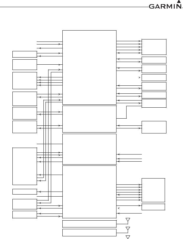
2.4 |
GTN Block Diagram |
|
|
|
|
|
*71 ;; ;; |
|
|
|
|
&211(&725 3 |
|
|
|
$,5&5$)7 32:(5 *5281' |
32:(5 *5281' |
/$7 '(9,$7,21 )/$*6 |
0$,1 &', +6, |
|
$,5&5$)7 /,*+7,1* %86 |
/,*+7,1* %86 |
72 )520 |
*36 925 ,/6 |
|
(;7(51$/ ,167580(17$7,21 |
7,0( 0$5. 287 |
9(57 '(9,$7,21 )/$*6 |
|
|
683(5)/$*6 |
|
||
|
|
|
|
|
|
672506&23( |
56 ,1 |
0$,1 2%6 |
|
|
56 287 |
|
|
|
|
|
|
|
|
|
|
|
$5,1& ,1 |
75$)),& |
|
)8(/ $,5 '$7$ |
|
',6&5(7(6 |
|
|
|
|
||
|
25 |
56 ,1 |
|
6:,7&+(6 |
|
6(5,$/,=(5 |
|
6:,7&+(6 |
|
|
|
$5,1& ,1 |
$1181&,$7256 |
$1181&,$7256 |
|
|
$5,1& 287 |
||
|
)/,*+7 &21752/ |
|
|
|
|
|
|
(;7(51$/ 0$3 |
|
|
6<67(0 |
,/6 *36 $3352$&+ |
56 287 |
|
|
|
/$7 '(9,$7,21 )/$*6 |
|
',63/$< |
|
|
9(57 '(9,$7,21 )/$*6 |
|
|
|
|
683(5)/$*6 |
56 ,1 |
75$16321'(5 |
|
|
|
56 287 |
|
|
*16 : : |
56 ,1 |
56 ,1 |
)/,*+7 675($0 |
|
6(5,(6 &5266),// |
56 287 |
56 287 |
|
|
|
56 ,1 |
56 ,1 |
|
|
|
56 287 |
56 287 |
*65 |
|
|
|
||
|
*$50,1 |
*71 ;; ;; |
|
|
|
(7+(51(7 ,1 &211(&725 3 |
|
||
|
*71 ;; ;; |
|
||
|
&5266),// |
(7+(51(7 287 |
|
|
|
|
|
',6&5(7(6 |
|
|
*$50,1 |
(7+(51(7 ,1 |
(7+(51(7 ,1 |
27+(5 *$50,1 /58V |
|
:($7+(5 5$'$5 |
|||
|
(7+(51(7 287 |
(7+(51(7 287 |
||
|
*71 ;; 21/< |
|
|
|
|
|
*71 |
|
|
|
|
&211(&725 3 |
|
|
|
$,5&5$)7 32:(5 *5281' |
32:(5 *5281' |
|
|
|
$8',2 3$1(/ |
&20 0,& .(< |
|
|
|
|
&20 5(027( 75$16)(5 |
&20 5(027( 75$16)(5 6:,7&+ |
|
|
|
&20 0,& $8',2 |
||
|
|
|
|
|
|
|
&20 $8',2 |
&20 5(027( 781( 83 |
&20 5(027( 781( |
|
|
|
||
|
|
$1$/2* $8',2 |
&20 5(027( 781( '2:1 |
6:,7&+(6 |
|
|
|
||
|
|
*71 |
|
|
|
|
&211(&725 3 |
|
|
|
|
9/2& $8',2 |
|
|
|
*0$21/< |
|
|
&', +6, |
|
|
|
|
|
|
|
|
/$7 '(9,$7,21 )/$*6 |
925 ,/6 21/< |
|
|
|
72 )520 |
|
|
50, |
925 2%, |
9(57 '(9,$7,21 )/$*6 |
|
|
683(5)/$*6 |
|
||
|
$,5&5$)7 32:(5 *5281' |
32:(5 *5281' |
925 2%6 |
|
|
9/2& &20326,7( 287 |
|
||
|
|
|
|
|
|
$5,1& |
|
1$9 ,/6 (1(5*,=( |
|
|
(),6 (+6, |
1$9 $5,1& ,1 |
6(5,$/ '0( &/2&. '$7$ |
.,1* 6(5,$/ |
|
|
|||
|
|
1$9 $5,1& 287 |
'0( 5(48(67 &20021 |
781(' '0( |
|
3$5$//(/ 781(' |
3$5$//(/ '0( 781,1* |
1$9 5(027( 75$16)(5 |
1$9 5(027( 75$16)(5 6:,7&+ |
|
'0( |
1$9 '0( &20021 |
|
|
|
|
*71 ;; ;; |
*36 6%$6 $17(11$ |
|
|
|
|
||
|
|
&211(&725 3 |
|
|
|
|
*71 |
&20 $17(11$ |
|
|
|
&211(&725 3 |
|
|
*71 |
|
1$9 $17(11$ |
|
|
|
&211(&725 3 |
|
|
Figure 2-4. GTN System Interface Diagram
190-01007-A1 |
System Maintenance Manual GTN 6XX/7XX Part 23 AML STC |
Rev. 7 |
Page 2-5 |
3 GTN CONTROL AND OPERATION
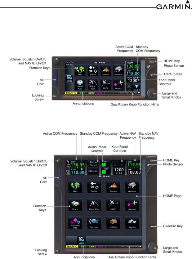
3.1GTN Controls
3.2GTN Normal Mode Overview
Figure 3-1. GTN 6XX Normal Mode Screen
Figure 3-2. GTN 7XX Normal Mode Screen
190-01007-A1 |
System Maintenance Manual GTN 6XX/7XX Part 23 AML STC |
Rev. 7 |
Page 3-1 |
3.3 Software Loading
3.3.1GTN Software Loader Card Creation
A GTN Software Loader Card may be created using GTN Downloadable Software and an SD card in conjunction with a GTN software application downloaded from the Dealer Resource Center on Garmin’s website. The Dealer Resource Center will allow the technician to choose which software package(s) to load onto the card.
NOTE
The downloadable application to create the GTN Software Loader Card only runs on PCs with Windows. Windows 2000, XP, Vista, and Windows 7 are supported. There is no Macintosh support at this time.
NOTE
An SD card reader is needed to create the GTN Software Loader card using the application that is downloaded from Garmin. The approved readers are SanDisk® SDDR-999 and SDDR-93, although other SD card readers will work.
Create a GTN Software Loader Card as follows:
1.Go to the Dealer Resource Center on Garmin’s website.
2.Download the GTN Software Loader Image. Refer to the Equipment List (P/N 005-00533-C1) for the correct Software Loader Image part number.
3.Ensure that you have an SD card reader connected to the PC. Insert the GTN Downloadable Software SD Card into the card reader.
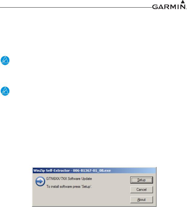
4.Run the executable file. The screen shown in Figure 3-3 will appear.
Figure 3-3. GTN Software Updater
5.Click Setup. The window shown in Figure 3-4 will appear to guide you through the software loader card creation process.
190-01007-A1 |
System Maintenance Manual GTN 6XX/7XX Part 23 AML STC |
Rev. 7 |
Page 3-2 |
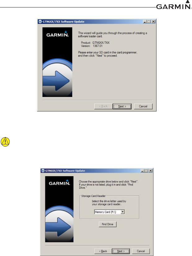
Figure 3-4. System and Software Version
6. Click Next and the window shown in Figure 3-5 will appear.
CAUTION
In order to create a GTN Software Loader Card, the drive that you select will be completely erased.
Figure 3-5. GTN Software Loader Card Formatting
190-01007-A1 |
System Maintenance Manual GTN 6XX/7XX Part 23 AML STC |
Rev. 7 |
Page 3-3 |
7.Ensure that the correct drive is selected. Click Next to create the card. Click Next to acknowledge any warnings that appear. The progress window in Figure 3-6 will appear when the card is being created.
Figure 3-6. Update Progress Window
8.After the card has been created, the window shown in Figure 3-7 in will appear. Click Finish to complete the update process.
Figure 3-7. Update Completion
9.Eject the card from the card reader (or stop the card reader in Windows). The GTN Software Loader Card is now ready to use.
190-01007-A1 |
System Maintenance Manual GTN 6XX/7XX Part 23 AML STC |
Rev. 7 |
Page 3-4 |

3.3.2GMA 35 Software Loading
NOTE
The GMA 35 software will be present on the SD card when creating a GTN Software Loader Card. A separate card is not required to perform GMA 35 software updates.
1.Remove power from the GTN 7XX by opening the circuit breaker
2.Insert the GTN Software Loader Card into the GTN 7XX data card slot (See Section 3.3.1 for instructions on how to create a GTN Software Loader Card).
3.Hold down the HOME key until Garmin is fully lit on the display after power is applied by closing the circuit breaker for the GTN 7XX.
4.Ensure the GMA 35 circuit breaker is also closed.
5.The Configuration Mode page should now be displayed. Touch the Updates key to display the software that is available.
6.To select GMA 35 software updates, touch the GTN Software Updates key on the top left corner of the display and select GMA 35 Software Updates.
7.To update the GMA 35 with all software available, touch Select All.
8.To begin the software update, touch the Update key on the bottom of the display.
9.The GTN will display the prompt, ‘Start GMA 35 Software Updates?’
10.Touch OK to allow the GTN to update the GMA 35.
11.When the updates are finished, the GTN will display ‘Update Complete!’
12.When finished, turn the GTN and GMA 35 off (open the circuit breaker) and remove the Software Loader Card. Reinsert the database card in the data card slot.
13.Restore power on the GTN and GMA 35 by closing the circuit breakers and ensure the software was updated correctly by going to the System Information page and selecting the GMA 35. Refer to Section 3.4.2 for more information on the System Information page.
190-01007-A1 |
System Maintenance Manual GTN 6XX/7XX Part 23 AML STC |
Rev. 7 |
Page 3-5 |
3.4 GTN Configuration Mode Overview
NOTE
When configuring the GTN, ensure that no configuration module service messages are displayed in the message queue. This would indicate that the configuration module is improperly wired or damaged.
Configuration mode is used to configure the GTN settings for each specific installation. To access configuration mode, perform the following steps:
1.Remove power from the GTN by opening the circuit breaker.
2.Press and hold the HOME key and reapply power to the GTN (push in the circuit breaker).
3.Release the HOME key when the display activates and the name ‘Garmin’ appears fully lit on the screen.
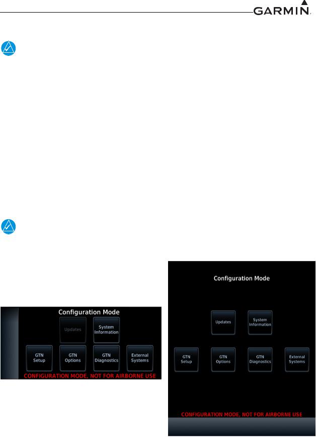
The first page displayed is the Configuration Mode page, as shown in Figure 3-8. For detailed information regarding how to configure the GTN, refer to the GTN 6XX/7XX AML STC Installation Manual,
P/N 190-01007-A3. While in configuration mode, pages can be selected by touching the desired key on the display. Some pages may require page scrolling to view all of the information and keys on the page. Scrolling is done by touching the screen and dragging the page in the desired direction, or by touching the Up or Down keys.
NOTE
The configuration pages shown here reflect main software version 3.00. Some differences in operation may be observed when comparing information in this manual to later software versions.
|
Figure 3-8. GTN 6XX and GTN 7XX Configuration Mode Pages |
|
|
190-01007-A1 |
System Maintenance Manual GTN 6XX/7XX Part 23 AML STC |
Rev. 7 |
Page 3-6 |
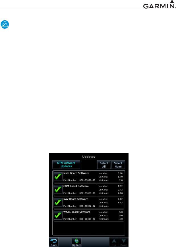
3.4.1GTN Software Updates
NOTE
The following steps will need to be repeated for each replacement GTN unit that requires a software update.
To update the GTN software, perform the following steps:
1.Remove power from the GTN by opening the circuit breaker.
2.Remove the database card and insert the correct GTN Software Loader Card into the data card slot. See Section 3.3.1 for creating a GTN Software Loader Card.
3.Restore power to the GTN by closing the circuit breaker.
4.The GTN is now in configuration mode as shown in Figure 3-8. Touch Updates to display the software updates that are available.
5.Check that the software version being loaded to the GTN matches the software version listed on the GTN STC Equipment List, 005-00533-C1. The Updates page displays the version that is installed on the unit and the version installed on the loader card.
6.Check that the available GTN software updates are being displayed by ensuring that GTN Software Updates key is highlighted in the upper left corner (upper right corner for 6XX) of the display.
7.To update the GTN with all software available, touch Select All.
8.To begin the software update, touch Updates on the bottom of the display.
9.The GTN will display the prompt, ‘Start GTN Software Updates?’
10.Touch OK to allow the GTN to go through the update process.
11.When the updates are finished, the GTN will display ‘Update Complete!’ When finished, remove power from the GTN and remove the Software Loader Card. Reinsert the database card into the data card slot.
|
Figure 3-9. GTN 7XX Updates Page |
|
|
190-01007-A1 |
System Maintenance Manual GTN 6XX/7XX Part 23 AML STC |
Rev. 7 |
Page 3-7 |
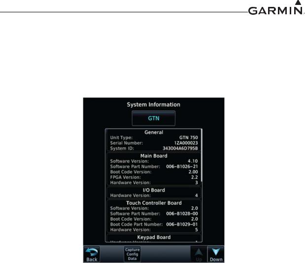
3.4.2System Information
View the System Information page, as shown in Figure 3-10, by touching System Information key on the Configuration Mode page. The System Information page displays the unit type, serial number, and system ID for the GTN. It also contains the software and hardware versions of the Main, I/O, Display, Keypad, LED, GPS/WAAS, COM and NAV boards. This information is also available for certain other LRUs connected to the GTN. Touch the GTN key and choose which LRU to display. Touch UP or DOWN to view all the information.
Figure 3-10. System Information Page
190-01007-A1 |
System Maintenance Manual GTN 6XX/7XX Part 23 AML STC |
Rev. 7 |
Page 3-8 |
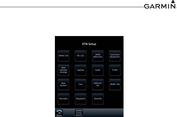
3.4.3GTN Setup Page
This section provides a brief overview of the pages that are accessed from the GTN Setup page, as shown in Figure 3-11, are described below. To access the GTN Setup page, touch the GTN Setup key from the Configuration Mode page as shown in Figure 3-8.
Figure 3-11. GTN 7XX Setup Pages
ARINC 429
This page allows the user to configure the ARINC 429 input and output ports on the GTN. Both ARINC 429 formats and bus speeds are set from this configuration page.
RS-232
This page allows the user to configure the RS-232 input and output ports on the GTN.
HSDB (Ethernet)
This page allows the user to set which Ethernet ports are connected.
Interfaced Equipment
This page allows the user to configure which LRUs are installed and interfaced to the GTN. The transponder selection is automatically configured when a valid transponder configuration is selected under the RS-232 page.
Main Indicator (Analog)
This page allows the user to calibrate the OBS resolver, and configure the CDI key, selected course for GPS and VLOC as well as the V-Flag state.
Lighting
This page allows the user to set the display parameters that affect the backlight and key lighting brightness.
Enhanced Lighting
This page replaces the ‘Lighting’ page when enabled under the ‘Main System’ configuration page. Enhanced lighting allows the user to set the display parameters that affect the backlight and key lighting brightness. Enhanced lighting may be used to configure separate Day/Night lighting curves.
190-01007-A1 |
System Maintenance Manual GTN 6XX/7XX Part 23 AML STC |
Rev. 7 |
Page 3-9 |

Audio
This page allows the user to configure the aural alert volume.
Traffic
This page allows the user to configure the traffic intruder symbol color and configure whether or not the GTN is the display used to control the traffic system.
Main System
This page allows the user to display miscellaneous configuration options for the GTN. Air/Ground Threshold, Air/Ground Discrete, Fuel Type, and Heading/Altitude input source connection statuses are settings on this page.
COM
This page allows the user to configure the RF squelch volume, Mic 1 Gain, and sidetone volume. These selections are only available for the GTN 635, 650, and 750 units.
VOR/LOC/GS
This page allows the user to check the CDI outputs from the VOR/LOC/GS receiver as well as the OBS resolver input to the VOR receiver. It is also used to format the DME tuning data. This selection is only available for the GTN 650 and 750 navigation units.
ARINC 708
This page allows the user to configure the GTN ARINC 708 input port. Selection of one of the approved ARINC 708 weather radars is only possible if the digital radar enablement is active. This setting is only available for the GTN 725 and 750 navigation units.
Discretes
This page allows the user to customize the configuration of discrete inputs/outputs on the J1001 and J1002 connectors.
Waypoints
These settings are not used in this STC.
Ownship
This page allows the user to select the displayed ownship icon from a list.
190-01007-A1 |
System Maintenance Manual GTN 6XX/7XX Part 23 AML STC |
|
Rev. 7 |
Page 3-10 |
|
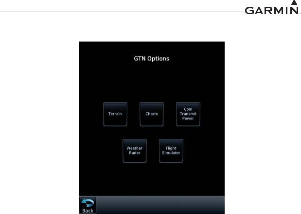
3.4.4GTN Options Page
Figure 3-12. GTN 7XX Options Pages
190-01007-A1 |
System Maintenance Manual GTN 6XX/7XX Part 23 AML STC |
|
Rev. 7 |
Page 3-11 |
|
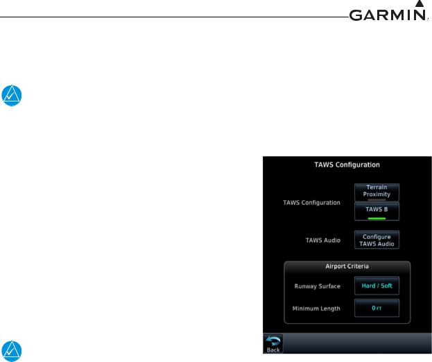
3.4.4.1TAWS-B Enablement
When the optional TAWS feature is enabled, the GTN will provide Class B TAWS functionality. This section describes how to reactivate the TAWS feature in the GTN.
NOTE
For first time TAWS enablement, refer to the GTN 6XX/7XX AML STC IM, P/N 190-01007-A3, for additional requirements and checkout procedures. This manual only describes the necessary steps to re-enable the feature for existing installations.
1.Turn the GTN off by pulling the NAV/GPS circuit breaker.
2.Remove the database SD card from the data card slot and insert the TAWS Enablement Card,
P/N 010-00878-01, which was used at the initial installation.
3.Enter configuration mode by applying power (closing the circuit breaker) to the GTN while holding the
HOME key.
4.Go to the Terrain Configuration page from the GTN Options page. Touch the TAWS B key.
When the TAWS feature is activated, the TAWS B key will be lit green, as shown in Figure 3-13.
NOTE
The feature enablement card should be provided to the customer after service has been completed.
3.4.4.1.1TAWS-B Configuration Options
Figure 3-13. GTN 7XX TAWS
Configuration Page
When TAWS-B is enabled as shown in Figure 3-13, the following configuration settings may be accessed:
TAWS Audio
This configuration setting allows the user to select aural alert messages for various caution and warning types.
Airport Criteria
The GTN TAWS alerting algorithm adapts the terrain alerting criteria based on nearby airports. The Airport Criteria configuration options allow the user to select the minimum criteria that the airport must meet to be considered as a nearby airport for the purpose of TAWS alerting. See Section 7.5.1 for more details.
190-01007-A1 |
System Maintenance Manual GTN 6XX/7XX Part 23 AML STC |
|
Rev. 7 |
Page 3-12 |
|
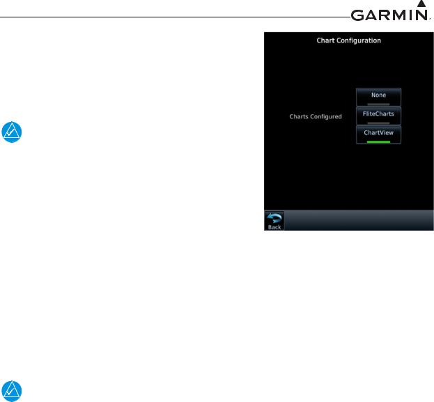
3.4.4.2ChartView™ Enablement (GTN 7XX Only)
The GTN 7XX can display Jeppesen charts using the optional ChartView feature, which must be activated. To configure which Charts to display, touch either None, FliteCharts, or ChartView. If ChartView is selected, it must be enabled as described below.
NOTE
For first time Chartview enablement, refer to the GTN 6XX/7XX AML STC IM, P/N 190-01007-A3, for additional requirements and checkout procedures. This manual only describes the necessary steps to re-enable the feature for existing installations.
1. Turn the GTN off by pulling the NAV/GPS circuit |
Figure 3-14. |
breaker. |
2.Remove the database SD card from the data card slot and insert the ChartView Enablement Card,
P/N 010-00878-04, which was used at the initial installation.
Chart Configuration
Page
3.Enter configuration mode on the GTN by applying power to the GTN (closing the circuit breaker) while holding the HOME key.
4.Go to the Charts page from the GTN Options page. Touch the ChartView key.
5.When the ChartView feature is activated, the ChartView key will be lit green, as shown in Figure 3-14.
NOTE
The feature enablement card should be provided to the customer after service has been completed.
190-01007-A1 |
System Maintenance Manual GTN 6XX/7XX Part 23 AML STC |
|
Rev. 7 |
Page 3-13 |
|
Loading...