


BZY97C91GP
FAGOR BZY97C91GP, BZY97C82GP, BZY97C75GP, BZY97C68GP, BZY97C62GP Datasheet
...
1.5 W Zener Diodes
BZY97C10 GP........ BZY97C200 GP
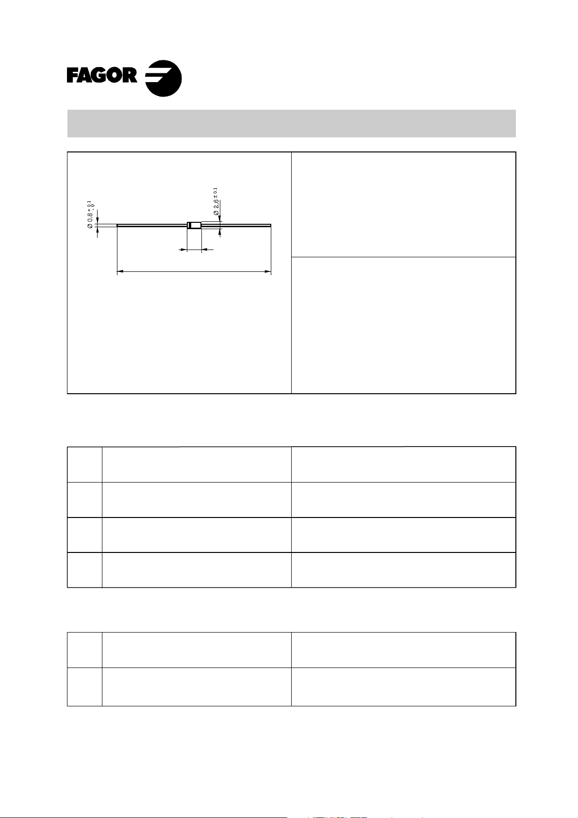
Dimensions in mm. DO-41
(Plastic)
± 0.2
5
±0.5
58.5
Mounting instructions
1. Min. distance from body to soldering point,
• Diffused junction
4 mm.
2. Max. solder temperature, 350 °C.
3. Max. soldering time, 3.5 sec.
4. Do not bend lead at a point closer than
2 mm. to the body.
• The plastic material carries
U/L recognition 94 V-0
• Terminals: Axial Leads
• Polarity: Color band denotes cathode
Maximum Ratings, according to IEC publication No. 134
Voltage
10 to 200 V
Power
1.5 W
P
tot
P
ZSM
T
j
T
stg
Power dissipation at Tamb = 60 oC
Non repetitive peak zener dissipation
(t = 10 ms.)
Operating temperature range
Storage temperature range
Electrical Characteristics at Tamb = 25°C
V
F
R
thj-a
Max. forward voltage drop at IF = 1.0 A
Max. thermal resistance at 10 mm.
lead length
1.5 W
40 W
– 55 to + 175 °C
– 55 to + 175 °C
1.1 V
50° C/W
Oct - 02
BZY97 GP
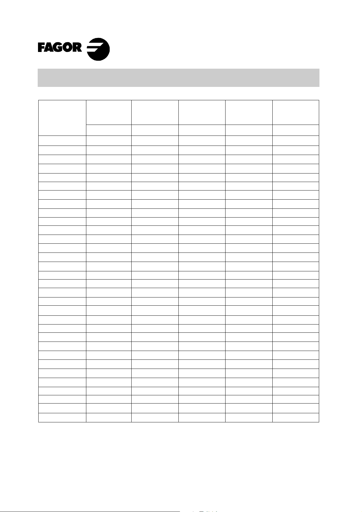
Type
BZY97C10 GP
BZY97C11 GP
BZY97C12 GP
BZY97C13 GP
BZY97C15 GP
BZY97C16 GP
BZY97C18 GP
BZY97C20 GP
BZY97C22 GP
BZY97C24 GP
BZY97C27 GP
BZY97C30 GP
BZY97C33 GP
BZY97C36 GP
BZY97C39 GP
BZY97C43 GP
BZY97C47 GP
BZY97C51 GP
BZY97C56 GP
BZY97C62 GP
BZY97C68 GP
BZY97C75 GP
BZY97C82 GP
BZY97C91 GP
BZY97C100 GP
BZY97C110 GP
BZY97C120 GP
BZY97C130 GP
BZY97C150 GP
BZY97C160 GP
BZY97C180 GP
BZY97C200 GP
Zener
Voltage
Range
V
at I
Z
ZT
9.4 - 10.6
10.4 - 11.6
11.4 - 12.7
12.4 - 14.1
13.8 - 15.8
15.3 - 17.1
16.8 - 19.1
18.8 - 21.2
20.8 - 23.3
22.8 - 25.6
25.1 - 28.9
28 - 32
31 - 35
34 - 38
37 - 41
40 - 46
44 - 50
48 - 54
52 - 60
58 - 66
64 - 72
70 - 79
77 - 88
85 - 96
94 - 106
104 - 116
114 - 127
124 - 141
138 - 156
153 - 171
168 - 191
188 - 212
Maximum
Zener
Impedance
Z
at I
ZT
ZT
4
7
7
10
10
15
15
15
15
15
15
15
15
40
40
45
45
60
60
80
80
100
100
200
200
250
250
300
300
350
350
350
Typical
Temperature
Coefficient
at I
ZT
o
(% /
C)(Ω)(V)
+ 0.070
+ 0.075
+ 0.075
+ 0.075
+ 0.075
+ 0.085
+ 0.085
+ 0.085
+ 0.085
+ 0.085
+ 0.085
+ 0.085
+ 0.085
+ 0.085
+ 0.085
+ 0.095
+ 0.095
+ 0.095
+ 0.095
+ 0.105
+ 0.105
+ 0.105
+ 0.105
+ 0.11
+ 0.11
+ 0.11
+ 0.11
+ 0.11
+ 0.11
+ 0.11
+ 0.11
+ 0.11
Test
Current
I
ZT
Min. Reverse
Voltage
at
IR
= 1µ A
V
(mA) (V)
50
50
50
50
50
25
25
25
25
25
25
25
25
10
10
10
10
10
10
10
10
10
10
5
5
5
5
5
5
5
5
5
5.0
5.0
7.0
7.0
10
10
10
10
12
12
14
14
17
17
20
20
24
24
28
28
34
34
41
41
50
50
60
60
75
75
90
90
R
Oct - 02
 Loading...