


 Loading...
CNC 8025 GP, M, MS
New Features |
(Ref. 0107 in) |
ERRORS FOUND IN THE INSTALLATION MANUAL (REF. 9707)
Appendix "F" page 10. P621(7)
It is wrong, it should say:
P621(7) The M06 function executes the M19 function (0=Yes, 1=No)
Appendix "G" page 20. P621(7)
It is wrong, it should say:
P621(7) The M06 function executes the M19 function (0=Yes, 1=No)
MODIFICATIONS TO THE INSTALLATION MANUAL (REF. 9707)
Comparison table xii. Technical description. Inputs/Outputs. |
|
|
|
|
Feedback inputs for rotary axes, it should say: |
W (GP), |
W (M), |
W (MG), |
W V (MS) |
Comparison table xii. Technical description. Axis control.
|
GP |
|
M |
MG |
MS |
Electronic threading. It should say |
|
|
x |
x |
x |
Comparison table xii. Technical description. Others. Add fields |
|
|
|
|
|
|
GP |
M |
MG |
MS |
|
Open loop motors without servodrives................................ |
x |
|
|
|
|
Laser machines...................................................................... |
|
x |
x |
x |
|
JIG Grinders........................................................................... |
|
x |
x |
x |
|
Section 3.3.3 (chapter 3 page 15). P612(6). Another example: |
|
|
|
|
|
Having a Fagor electronic handwheel (25 lines/turn) set as follows: |
|
|
|
||
P612(3) = 0 Millimeters |
P612(4) = 0 and P612(5) = 0 Resolution: 0.001 mm. |
||||
P612(6) = 0 Multiplication factor x4 |
|
|
|
|
|
Depending on the position of the MFO switch (Manual Feedrate Override) the selected axis will move:
Position |
1 |
1 x 25 x 4 = 0.100 mm per turn |
||
Position |
10 |
10 x 25 x 4 |
= |
1.000 mm per turn |
Position |
100 |
100 x 25 x 4 |
= |
10.000 mm per turn |
MODIFICATIONS TO THE PROGRAMMING MANUAL (REF. 9701)
Section 6.30.4 (page 128). G76 Automatic block generation
If the new program to be created is to be sent to a PC (G76 N), the DNC communication must be enabled and, at the PC, the "program management" "Digitizing Reception" option must be selected.
If it is not, the CNC will issue error 56.
- 2 -
Version 7.1 (July 1996)
1. EXPANSION OF THE INTEGRATED PLC RESOURCES
1.1 INPUTS
1.1.1 AXIS BEING HOMED (REFERENCED)
Input I88 indicates whether a home search is taking place and inputs I100, I101, I102, I103 and I104 indicates which axis is being homed.
I88 |
Indicates whether any axis is being homed (0=No / 1=Yes) |
I100 |
Indicates whether the X axis is being homed (0=No / 1=Yes) |
I101 |
Indicates whether the Y axis is being homed (0=No / 1=Yes) |
I102 |
Indicates whether the Z axis is being homed (0=No / 1=Yes) |
I103 |
Indicates whether the W axis is being homed (0=No / 1=Yes) |
I104 |
Indicates whether the V axis is being homed (0=No / 1=Yes) |
1.1.2 AXIS MOVING DIRECTION
Inputs I42, I43, I44, I45 and I46 will show, at all times, the moving direction of each axis.
|
I42 |
Indicates the moving direction of the X axis (0=Positive / 1=negative) |
|
I43 |
Indicates the moving direction of the Y axis (0=Positive / 1=negative) |
|
I44 |
Indicates the moving direction of the Z axis (0=Positive / 1=negative) |
|
I45 |
Indicates the moving direction of the W axis (0=Positive / 1=negative) |
|
I46 |
Indicates the moving direction of the V axis (0=Positive / 1=negative) |
1.2 |
OUTPUTS |
|
1.2.1 |
ENABLING THE CYCLE-START KEY VIA PLCI |
|
With this feature it is possible to set the treatment of the [CYCLE START] of the CNC via PLCI. Machine parameter "P627(7)" indicates whether this feature is available or not.
P627(7) = 0This featureis not available.
P627(7) = 1This feature is available.
When using this feature, the way the CNC handles the [CYCLE START] key depends on the status of PLCI output O25 (CYCLESTARTENABLE).
O25 = 0 The CNCignoresboth the [CYCLE-START] key and the external [CYCLE-START] signal.
O25 = 1 The CNC takes into account both the [CYCLE-START] key and the external [CYCLE-START] signal.
1.2.2 TRAVEL LIMITS SET VIA PLCI
With this feature, the travel limits of the axes may be set via PLCI. Machine parameter "P627(7)" indicates whether this feature is available or not.
P627(7) = 0This featureis not available.
P627(7) = 1This feature is available.
To set the travel limits for each axis, use the following outputs:
O52 / O53 |
Positive / negative X axis limits |
O54 / O55 |
Positive / negative Y axis limits |
O56 / O57 |
Positive / negative Z axis limits |
O58 / O59 |
Positive / negative W axis limits |
O60 / O61 |
Positive / negative V axis limits |
When the PLCI activates one of this outputs while the axis is moving in the same direction, the CNC stops the axes and the spindle and it displays an axis-travel-limit-overrun error.
- 3 -
1.2.3 DENYING ACCESS TO THE EDITOR MODE VIA PLCI
Machine parameter"P627(7)" indicates whether this feature is available or not.
P627(7) = 0This featureis not available.
P627(7) = 1This feature is available.
When using this feature, access to the editor mode at the CNC depends on the status of PLCI output O26, as well as on the current conditions (protected memory, number of the program to be locked).
O26 = 0 Free access to the editor mode (it is protected by current conditions).
O26 = 1 Denied access to the editor mode.
1.2.4 SPINDLE CONTROLLED VIA CNC OR VIA PLCI
From this version on, the spindle analog output may be set either by the CNC or by the PLCI. Machine parameter "P627(7)" indicates whether this feature is available or not.
P627(7) = 0This featureis not available
P627(7) = 1This feature is available
Setting the spindle analog output via PLCI
To do this, use the combination: M1956 - R156.
Register R156 sets the spindle analog output in units of 2.442 mV. (10 / 4095)
R156 = 0000 1111 1111 1111 |
(R1256=4095) |
= 10V. |
R156 = 0001 1111 1111 1111 |
(R1256=1) |
=-10V. |
R156 = 0000 0000 0000 0001 |
= 2.5 mV. |
|
R156 = 0001 0000 0000 0001 |
|
=-2.5mV. |
In order for the CNC to assume the value allocated to register R156, one must activate mark M1956 as described in the PLCI Manual (section 5.5.2. Writing internal CNC variables).
Spindle controlled either by the CNC or by the PLCI
The CNC may have two internal spindle analog outputs, that of the CNC itself and the one set by the PLCI.
Use PLCI output O27 to "tell" the CNC which one of them to output.
O27 = 0 |
Spindle analog output set by the CNC itself. |
O27 = 1 |
Spindle analog output set by the PLCI (combination: M1956-R156). |
1.3 READING INTERNAL CNC VARIABLES
From this version on, the PLCI and the PLC64 have access to more internal CNC information.
With the PLCI, there is no need to activate a mark to access this information. The CNC itself updates this information at the beginning of each PLCI cycle scan.
With the PLC 64, the corresponding mark must be consulted every time a CNC variable is to be checked.
The CNC information now accessible is:
Real S in rpm (REG119 at the PLCI, M1919 at the PLC64)
Not to be mistaken with R112 which indicates the programmed Spindle speed (S).
It is given in rpm and in hexadecimal format. Example: S 2487 R119= 967
Number of the block in execution (REG120 at the PLCI, M1920 at the PLC64)
It is given in hexadecimal format. Example: N120 R120= 78
Code of the last key pressed (B0-7 REG121 at the PLCI, Not available at the PLC64)
Not to be mistaken with register R118 which also indicates the code corresponding to the last key pressed,but-
-
When pressing a key, both registers have the same value; butthe data in R121 is only kept there for one cycle scan whereas R118 keeps its value until another key is pressed.
When pressing the same key several times, (for example: 1111): R121 will show code "1" four times (once per cycle scan).
R118 will always show the same value, thus not being able to tell whether the "1" key has been pressed once or more times.
The key codes are listed in the appendix of the PLCI manual.
- 4 -
Operating mode selected at the CNC |
(B8-11 REG121 at the PLCI, |
Not available at the PLC64) |
||||||
|
B8 |
B9 |
B10 |
|
B11 |
|
|
|
|
0 |
0 |
0 |
|
0 |
Automatic |
|
|
|
0 |
0 |
0 |
|
1 |
Single block |
|
|
|
0 |
0 |
1 |
|
0 |
Play-Back |
|
|
|
0 |
0 |
1 |
|
1 |
Teach-in |
|
|
|
0 |
1 |
0 |
|
0 |
Dry-Run |
|
|
|
0 |
1 |
0 |
|
1 |
JOG |
|
|
|
0 |
1 |
1 |
|
0 |
Editor |
|
|
|
0 |
1 |
1 |
|
1 |
Peripherals |
|
|
|
1 |
0 |
0 |
|
0 |
Tool Table and G functions |
|
|
|
1 |
0 |
0 |
|
1 |
Special modes |
|
|
Status of the miscellaneous "M" functions |
(REG122 at the PLCI, |
Not available at the PLC64) |
||||||
The status of each one of these functions is given by a bit and will appear as a "1" when active and "0" when inactive.
B15 |
B14 |
B13 |
B12 |
B11 |
B10 |
B9 |
B8 |
B7 |
B6 |
B5 |
B4 |
B3 |
B2 |
B1 |
B0 |
|
|
|
|
|
|
|
M19 |
M1 |
M30 |
M6 |
M5 |
M4 |
M3 |
M2 |
M0 |
2. RETRACE FUNCTION.
This feature is available on the following models:
CNC-8025M |
CNC-8025MG |
CNC-8025MS |
CNC-8025MI |
CNC-8025MGI |
CNC-8025MSI |
Machine parameter "P627(6)" indicates whether this feature is available or not.
P627(6) = 0 |
This featureis not available |
P627(6) = 1 |
This feature is available |
This function may be selected by the operator. To do this, activate:
On models without PLCI: |
pin 7 of connector A5. |
On modelswithPLCI: |
PLCI output O47 |
Operation:
As the CNC executes motion blocks, it always stores the last 10 blocks already executed
Whenever it executes a block containing an M,S,T type function, the machining conditions change and the CNC deletes those previously stored motion blocks.
When the retrace function is activated, the block currently in execution is interrupted and the retrace process begins.
First to the starting point of the current block and, then, to that of the previously stored program blocks.
If all the stored blocks are executed, the CNC stops the machine until the retrace function is canceled.
When this function is canceled, the CNC interrupts the current movement (if any) and it executes all the retraced blocks again. Once the interruption point is reached, the CNC resumes the execution of the program.
3. OPERATION WITH TWO MOTORS AND 3 AXES.
Machine parameter "P627(8)" indicates whether this feature is available or not.
P627(8) = 0This featureis not available.
P627(8) = 1This feature is available.
Operation:
The CNC permits using 2 motors to move 3 axes with the following conditions:
One of the axes shared by a motor must be the Z axis and the other one must be either the X or the Y axis.
Only interpolations between the X and Y axes are possible. The Z axis cannot be interpolated with any other axis. It must be moved alone.
Example: To move the tool from "X0 Y0 Z0" to "X20 Y20 Z20", The CNC will make this move in two steps. First, it will move the X and Y axes to X20 Y20 and, then, the Z axis to Z20.
- 5 -

4. SPINDLE FOLLOWING ERROR DISPLAY WHILE IN M19
From this version on, when operating with spindle orient (M19), the CNC also shows the spindle following error on the screen corresponding to the following error in Automatic and Single block modes.
The Following Error screen shows, in large characters, the amount of axis lag and, under it, the following information line.
F 00000.0000 & 100 S 0000 % 100 T 00.00 S 0000.000
The last value of this line"S 0000.000" shows the amount of following error (lag) of the spindle when it operates in spindle orient mode (M19).
5. GANTRY AXES NOT MECHANICALLY SLAVED
From this version on, depending on the setting of machine parameter "P629(8)", it is possible to work with two different types of Gantry axes.
"P629(8)=0" |
Mechanically slaved Gantry Axes. As until now. |
|
When being homed, both axes behave as a single axis. The CNC takes into account only the parameter |
|
settings and feedback pulses of the main axis, the slaved one being just a follower of the main axis, |
"P629(8)=1" |
Not-mechanically slaved Gantry axes. |
|
When being homed, the two axes behave as separate independent axes. First the main axis is homed |
|
and, then, the slaved one. |
6. SHEETMETAL FORMING MACHINES
This feature is available on GP models.
To enable it, set machine parameter "P626(7)=1". The CNC enables functions M98 and M99 to control the X axis positioning loop.
Function M98 opens the X axis loop and M99 closes it.
When the CNC executes an M30, it also closes the X axis positioning loop.
When operating in jog mode, the CNC enables he following keys to control the X axis positioning loop:
Executes an M98 opening the X axis loop.
Executes an M98 opening the X axis loop.
Executes an M98 closing the X axis loop.
Version 7.2 (April 1997)
1. SCREEN SAVER
The screen saver function works as follows:
After 5 minutes without pressing a key or without the CNC refreshing the screen, the screen goes blank. Press any key to restore the display.
Machine parameter "P626(5)" indicates whether this feature is to be used or not.
P626(5) = 0This feature is not being used.
P626(5) = 1This feature is being used.
2. JOGGING FEEDRATE
If while in JOG mode, the conditional input (block skip), pin 18 of connector I/O1, the CNC does not allow entering a new F value. Only the feedrate override (%) may be varied by means of the MFO switch.
- 6 -
3. PARAMETRIC PROGRAMMING. NEW FUNCTION: F34
Function F34 returns the number of the tool being dealt with.
P27=F34 Parameter P27 takes the value of the new tool being dealt with.
This function must be used when working with a subroutine associated with the tool change. When using it outside that subroutine, function F34 returns the value of "100".
Version 7.3 (March 1998)
1. PLCI. Input I87
While the CNC is threading (G84), PLCI input I87 is set to “1”.
Note: Input I97 indicates rigid tapping.
Version 7.4 (May 1999)
1. NEW MACHINE PARAMETER ASSOCIATED WITH THE M FUNCTIONS
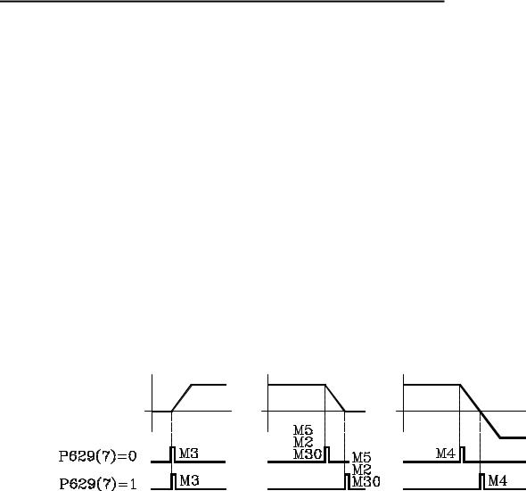
Machine parameter "P629(7)" indicates when the M3, M4, M5 functions are sent out while accelerating or decelerating the spindle.
2. CANCEL TOOL OFFSET DURING A TOOL CHANGE
From this version on, it is possible to execute a "T.0" type block inside the subroutine associated with the tool to cancel the tool offset. This lets move to a particular position without the need for cumbersome calculations.
Only the tool offset may be canceled (T.0) or modified (T.xx). The tool cannot be changed (Txx.xx) inside the subroutine associated with the tool.
3. DIVIDING FACTOR FOR FEEDBACK SIGNALS
Parameters P631(8), P631(7), P631(6), P631(5) and P631(4) are used together with P604(8), P604(7), P604(6), P604(5) and P616(8) which indicate the multiplying factor to be applied to the feedback signals of the X, Y, Z, W, V axes respectively.
X axis |
Yaxis |
Z axis |
W axis |
Vaxis |
P604(8) |
P604(7) |
P604(6) |
P604(5) |
P616(8) |
P631(8) |
P631(7) |
P631(6) |
P631(5) |
P631(4) |
Indicate whether the feedback signals are divided (=1) or not (=0). |
||||
P631(8)=0,P631(7)=0,P631(6)=0,P631(5)=0andP631(4)=0 |
They are not divided |
|||
P631(8)=1,P631(7)=1,P631(6)=1,P631(5)=1andP631(4)=1 |
They are divided by two. |
|||
Example:
We wish to obtain a resolution of 0.01 mm with a squarewave encoders mounted on the X axis with 5mm pitch ballscrew Nr of pulses = ballscrew pitch / (Multiplying factor x Resolution)
With P604(8)=0 & P631(8)=0 |
x4 multiplying factor |
Nr of pulses = 125 |
With P604(8)=1 & P631(8)=0 |
x2 multiplying factor |
Nr of pulses = 250 |
With P604(8)=0 & P631(8)=1 |
x2 multiplying factor |
Nr of pulses = 250 |
With P604(8)=1 & P631(8)=1 |
x1 multiplying factor |
Nr of pulses = 500 |
- 7 -

Version 7.6 (July 2001)
1. G75 AFFECTED BY FEEDRATE OVERRIDE
From this version on, there is a new machine parameter indicating whether G75 is affected by the feedrate override or not.
P631(1) = 0Not affected. It is always at 100%, like in previous versions. P631(1) = 1It is affected by the Feedrate override.
2. |
FEEDBACK FACTOR. |
|
|
|
|
|
|
|
From this version on, there is a new machine parameter to set the resolution of an axis having an encoder and a leadscrew. |
||||||
|
P819 Feedback factor for the X axis |
P820 Feedback factor for the Y axis |
P821 Feedback factor for the Z axis |
||||
|
P822 Feedback factor for the W axis |
P823 Feedback factor for the V axis |
|
|
|||
|
Values between 0 and 65534. The “0” value indicates that this feature is not being used. |
|
|||||
|
Use the following formula to calculate the “Feedback Factor” : |
|
|
|
|||
|
Feedback factor = (Gear Ratio x Leadscrew pitch / Number of Encoder pulses) x 8.192 |
|
|||||
|
Examples: |
Gear Ratio |
1 |
1 |
2 |
1 |
|
|
|
Leadscrew pitch |
5000 |
6000 |
6000 |
8000 |
(microns) |
|
|
Encoder |
2500 |
2500 |
2500 |
2500 |
(pulses/turn) |
|
|
Feedback factor |
16384 |
19660.8 |
39321.6 |
26214.4 |
|
The machine parameters only admit integer values and sometimes the “Feedback Factor” has decimals. In those cases, assign the integer part to the machine parameter and use the leadscrew compensation table to make up for the decimal part.
The values to be entered in the table are calculated with the following formula:
Leadscrew position = Leadscrew Error (microns) x Integer of feedback factor / decimals of the feedback factor
For example: Gear ratio = 1 |
Leadscrew pitch = 6000 |
Encoder = 2500 |
||
Feedback factor = 19660.8 |
|
|
Machine parameter = 19660 |
|
For a leadscrew error of 20 microns |
|
Leadscrew position = 20 x 19660 / 0.8 = 491520 |
||
Going on with the calculation, we come up with the following table. |
||||
Leadscrew position |
Leadscrew error |
|||
P0 = |
-1966.000 |
P1 = |
-0.080 |
|
P2 = |
-1474.500 |
P3 = |
-0.060 |
|
P4 = |
-983.000 |
P5 = |
-0.040 |
|
P6 = |
-491.500 |
P7 = |
-0.020 |
|
P8 = |
0 |
P9 = |
0 |
|
P10 = |
491.500 |
P11 = |
0.020 |
|
P12 = |
983.000 |
P13 = |
0.040 |
|
P14 = |
1472.500 |
P15 = |
0.060 |
|
P16 = |
1966.000 |
P17 = |
0.080 |
|
3. NEW MODEL
From this version on, the new model MLI is now available.
It offers the same features as the MGI model and it is sold together with the motors and ACS drives..
Headquarters (SPAIN): Fagor Automation S. Coop. Bº San Andrés s/n, Apdo. 144 20500 Arrasate - Mondragón Tel: +34-943-719200
Fax: +34- 943-791712 +34-943-771118 (Service Dept.)
www.fagorautomation.com E-mail: info@fagorautomation.es
- 8 -
FAGOR 8025/8030 CNC
Models: M, MG, MS, GP
OPERATING MANUAL
Ref. 9701 (in)
ABOUT THE INFORMATION IN THIS MANUAL
This manual is addressed to the machine operator. It describes how to operate with this 8025 CNC.
It includes the necessary information for new users as well as advanced subjects for those who are already familiar with this CNC product.
It may not be necessary to read this whole manual. Consult the list of "New Features and Modifications" which will indicate to you the chapters and sections describing them.
Consult the Comparison Table in order to find the specific features offered by your particular CNC model.
There is also an appendix on error codes which indicates some of the probable reasons which could cause each one of them.
Notes: The information described in this manual may be subject to variations due to technical modifications.
FAGOR AUTOMATION, S.Coop. Ltda. reserves the right to modify the contents of the manual without prior notice.
INDEX
Section |
|
Page |
|
Comparison table for Mill Model FAGOR 8025/8030 CNCs ......................................... |
ix |
|
New features and modifications ...................................................................................... |
xv |
INTRODUCTION |
|
|
|
Safety Conditions ........................................................................................................... |
Intr. 3 |
|
Material Returning Terms ............................................................................................. |
Intr. 5 |
|
Fagor Documentation for the 8025/30 M CNC .......................................................... |
Intr. 6 |
|
Manual Contents ............................................................................................................ |
Intr. 7 |
1. |
Overview .......................................................................................................................... |
1 |
2. |
Front panel 8025/30 CNC ............................................................................................... |
2 |
2.1. |
Monitor/keyboard for the 8030 CNC ............................................................................. |
2 |
2.2. |
Control panel for the 8030 CNC ..................................................................................... |
4 |
2.3. |
Monitor/keyboard/control panel for the 8025 CNC ...................................................... |
5 |
2.4. |
Selection of colors ........................................................................................................... |
7 |
2.5. |
Cancellation of monitor display ..................................................................................... |
7 |
2.6. |
Function keys (soft keys) ................................................................................................ |
7 |
3. |
OPERATING MODES ..................................................................................................... |
8 |
3.1. |
0 mode: AUTOMATIC (Continuous cycle) / 1 mode: SINGLE BLOCK ....................... |
10 |
3.1.1. |
Execution of a program ................................................................................................... |
10 |
3.1.1.1. |
Selection of the Automatic (0) Single Block (1) operating modes ............................... |
10 |
3.1.1.2. |
Selection of the program to be executed ........................................................................ |
10 |
3.1.1.3. |
Selection of the first block to be executed ..................................................................... |
11 |
3.1.1.4. |
Display of the contents of the blocks ............................................................................. |
11 |
3.1.1.5. |
Cycle Start ....................................................................................................................... |
12 |
3.1.1.6. |
Cycle Stop ....................................................................................................................... |
12 |
3.1.1.7. |
Changing the operating mode ........................................................................................ |
13 |
3.1.2. |
Display modes ................................................................................................................. |
13 |
3.1.2.1. |
Selection of the display mode ........................................................................................ |
13 |
3.1.2.2. |
Standard display mode .................................................................................................... |
14 |
3.1.2.3. |
Current position display mode ....................................................................................... |
15 |
3.1.2.4. |
Following error display mode ......................................................................................... |
15 |
3.1.2.5. |
Arithmetic parameters display mode .............................................................................. |
15 |
3.1.2.6. |
Subroutine status, clock and parts counter display mode .............................................. |
16 |
3.1.2.7. |
Graphics display mode .................................................................................................... |
17 |
3.1.3. |
Programming while running a program. Background .................................................... |
18 |
3.1.4. |
PLC/LAN mode ............................................................................................................... |
18 |
3.1.5.Verification and modification of the values of the tool offset table
|
without stopping the cycle ............................................................................................. |
19 |
3.1.6. |
Tool inspection ............................................................................................................... |
19 |
3.1.7. |
CNC reset ........................................................................................................................ |
21 |
3.1.8. |
Display and deletion of the Messages sent by the FAGOR PLC 64. .............................. |
21 |
3.2. |
Mode 2: PLAY-BACK .................................................................................................... |
22 |
3.2.1 |
Selection of the operating mode PLAY-BACK .............................................................. |
22 |
Section |
|
Page |
|
|
|
3.2.2. |
Locking/Unlocking of memory ...................................................................................... |
22 |
3.2.3. |
Deletion of a complete program ...................................................................................... |
22 |
3.2.4. |
Change of program number ............................................................................................. |
22 |
3.2.5. |
Display and search of memorized subroutines ............................................................... |
22 |
3.2.6. |
Selection of a program .................................................................................................... |
22 |
3.2.7. |
Creating a program .......................................................................................................... |
23 |
3.2.8. |
Deletion of a block .......................................................................................................... |
23 |
3.2.9. |
Copy a program ............................................................................................................... |
23 |
3.3. |
MODE 3: TEACH-IN ....................................................................................................... |
24 |
3.3.1. |
Selection of the operating mode TEACH-IN .................................................................. |
24 |
3.3.2. |
Locking/Unlocking of memory ....................................................................................... |
24 |
3.3.3. |
Deletion of a complete program ...................................................................................... |
24 |
3.3.4. |
Change of program number ............................................................................................ |
24 |
3.3.5. |
Display and search of memorized subroutines ............................................................... |
24 |
3.3.6. |
Selection of a program .................................................................................................... |
24 |
3.3.7. |
Program creation ............................................................................................................. |
25 |
3.3.8. |
Deletion of a block .......................................................................................................... |
25 |
3.3.9. |
Copy a program ............................................................................................................... |
25 |
3.4. |
Mode 4: DRY RUN ......................................................................................................... |
26 |
3.4.1. |
Execution of a program ................................................................................................... |
26 |
3.4.1.1. |
Selection of the operating mode DRY RUN (4) ............................................................. |
26 |
3.4.1.1.1. |
Selection of execution mode ........................................................................................... |
28 |
3.4.1.2. |
Selection of the program to be executed ......................................................................... |
29 |
3.4.1.3. |
Selection of starting block ............................................................................................... |
29 |
3.4.1.4. |
Display of the contents of the blocks .............................................................................. |
29 |
3.4.1.5. |
Cycle Start ....................................................................................................................... |
29 |
3.4.1.6. |
Cycle Stop ....................................................................................................................... |
29 |
3.4.1.7. |
Change of operating mode .............................................................................................. |
29 |
3.4.1.8. |
Tool inspection ................................................................................................................ |
30 |
3.4.2. |
Display modes ................................................................................................................. |
30 |
3.5. |
Mode 5: JOG ................................................................................................................... |
31 |
3.5.1. |
Selection of the JOG operating mode ............................................................................. |
31 |
3.5.2. |
Search for machine reference axis by axis ...................................................................... |
32 |
3.5.3. |
Presetting a coordinate value .......................................................................................... |
32 |
3.5.4. |
Jogging the axes .............................................................................................................. |
33 |
3.5.4.1. |
Continuous movement ..................................................................................................... |
33 |
3.5.4.2. |
Incremental movement .................................................................................................... |
34 |
3.5.5. |
Entering F,S and M ......................................................................................................... |
34 |
3.5.5.1. |
Entering an F value ......................................................................................................... |
34 |
3.5.5.2. |
Entering an S value ......................................................................................................... |
35 |
3.5.5.3. |
Entering an M value ........................................................................................................ |
35 |
3.5.6. |
Operation of the CNC as a readout ................................................................................. |
35 |
3.5.7. |
Change of measurement units ......................................................................................... |
36 |
3.5.8. |
Handwheel operation ....................................................................................................... |
36 |
3.5.9. |
Display/Modification of RANDOM table ....................................................................... |
37 |
3.5.10. |
Measuring and loading of tool offsets with a probe ....................................................... |
40 |
3.5.11. |
Spindle operating keys .................................................................................................... |
41 |
3.6. |
Mode 6: EDITING .......................................................................................................... |
42 |
3.6.1. |
Selection of the operating mode EDITING(6) ................................................................ |
42 |
3.6.2. |
Locking/Unlocking of memory and formatting of 512 Kb memory .............................. |
42 |
3.6.3. |
Part-program directory .................................................................................................... |
43 |
3.6.3.1. |
Deletion of a complete program ...................................................................................... |
43 |
3.6.4. |
Change of program number ............................................................................................ |
44 |
3.6.5. |
Display and search of subroutines stored in memory ..................................................... |
44 |
3.6.6. |
Selection of a program .................................................................................................... |
45 |
3.6.7. |
Creating a program .......................................................................................................... |
45 |
3.6.7.1 |
Displaying the block contents ......................................................................................... |
45 |
3.6.7.2. |
Unassisted programming ................................................................................................. |
46 |
3.6.7.3. |
Modification and deletion of a block .............................................................................. |
47 |
3.6.7.4. |
Assisted programming ..................................................................................................... |
48 |

Section |
|
Page |
3.6.7.5. |
Save a program being edited (only on models with 512 Kb of memory) ....................... |
49 |
3.6.7.6. |
Copying a program .......................................................................................................... |
49 |
3.7. |
Mode 7: PERIPHERALS ................................................................................................ |
50 |
3.7.1. |
Selection of the operating mode PERIPHERALS (7) ..................................................... |
50 |
3.7.2. |
Entering a program from the FAGOR cassette/recorder (0) ........................................... |
51 |
3.7.2.1. |
Transmission errors ......................................................................................................... |
53 |
3.7.3. |
Transferring a program to the FAGOR cassette recorder (1) ........................................... |
53 |
3.7.3.1. |
Transmission errors ......................................................................................................... |
54 |
3.7.4. |
Entering a program from a peripheral other than the FAGOR cassette/recorder (2) ..... |
55 |
3.7.5. |
Transferring a program to a peripheral other than the FAGOR cassette/recorder (3) .... |
55 |
3.7.6. |
FAGOR cassette’s directory (4) ...................................................................................... |
56 |
3.7.7. |
Deletion of a FAGOR cassette program (5) .................................................................... |
56 |
3.7.8. |
Interruption of the transmission process ......................................................................... |
57 |
3.7.9. |
DNC. Communication with a computer .......................................................................... |
57 |
3.8. |
Mode 8: TOOL OFFSETS AND ZERO OFFSETS G53/G59 ........................................ |
58 |
3.8.1. |
Selection of the operating mode TOOL OFFSET (8) ..................................................... |
58 |
3.8.2. |
Read-out of tool table ...................................................................................................... |
58 |
3.8.3. |
Entering the dimensions of the tools ............................................................................... |
59 |
3.8.4. |
Modification of tool dimensions ..................................................................................... |
59 |
3.8.5. |
Change of measurement units ......................................................................................... |
60 |
3.8.6. |
Zero offsets ...................................................................................................................... |
61 |
3.8.6.1. |
Displaying the zero offset table ....................................................................................... |
61 |
3.8.6.2. |
Entering zero offset values .............................................................................................. |
61 |
3.8.6.3. |
Modification of zero offset values .................................................................................. |
62 |
3.8.6.4. |
Change of measuring units .............................................................................................. |
62 |
3.8.7. |
Return to the tool offset table .......................................................................................... |
62 |
3.8.8. |
Complete deletion of tool offsets or zero table ............................................................... |
62 |
3.9. |
Mode 9: SPECIAL MODES ........................................................................................... |
62 |
3.10. |
Graphics ........................................................................................................................... |
63 |
3.10.1. |
Display area definition .................................................................................................... |
64 |
3.10.2. |
Zooming (windowing) .................................................................................................... |
65 |
3.10.3. |
Redefinition of the display area by the Zoom function .................................................. |
66 |
3.10.4. |
Deletion of graphics ........................................................................................................ |
66 |
3.10.5. |
Graphic representation in color ...................................................................................... |
66 |
|
ERROR CODES |
|

COMPARISON TABLE FOR MILL MODEL FAGOR 8025/8030 CNCs
8025/8030 MILL MODEL CNCS
Fagor offers the 8025 and 8030 mill type CNCs.
Both types operate the same way and offer similar characteristics. Their basic difference is that the former is compact and the latter is modular.
Both CNC types offer basic models. Although the differences between the basic models are detailed later on, each model may be defined as follows:
8025/8030 GP |
Oriented to General Purpose machines |
8025/8030 M |
Oriented to Milling machines of up to 4 axes. |
8025/8030 MG |
Same as the M model, but with dynamic graphics. |
8025/8030 MS |
Oriented to Machining Centers (up to 5 axes). |
When the CNC has an Integrated Programmable Logic Controller (PLCI), the letter "I" is added to the CNC model denomination: GPI, MI, MGI, MSI.
Also, When the CNC has 512Kb of part-program memory, the letter "K" is added to the CNC model denomination: GPK, MK, MGK, MSK, GPIK, MIK, MGIK, MSIK.
|
Basic |
With PLCI |
Basic |
With PLCI |
|
|
|
With 512Kb |
and 512Kb |
|
|
|
|
|
General Purpose |
GP |
GPI |
GPK |
GPKI |
|
|
|
|
|
Mills up to 4 axes |
M |
MI |
MK |
MIK |
|
|
|
|
|
Up to 4 axes with graphics |
MG |
MGI |
MGK |
MGIK |
|
|
|
|
|
Machining Centers |
MS |
MSI |
MSK |
MSIK |
|
|
|
|
|

TECHNICAL DESCRIPTION
|
|
GP |
M |
MG |
MS |
|
|
|
|
|
|
|
|
|
|
|
INPUTS/OUTPUTS |
6 |
6 |
6 |
6 |
|
|
|
Feedback inputs. ........................................................................................ |
|
|
||||
|
Linear axes ........................................................................... |
4 |
4 |
4 |
5 |
|
|
|
Rotary axes ........................................................................... |
2 |
2 |
2 |
2 |
|
|
|
Spindle encoder .................................................................... |
1 |
1 |
1 |
1 |
|
|
|
Electronic handwheels ......................................................... |
1 |
1 |
1 |
1 |
|
|
|
Probe input ............................................................................................. |
x |
x |
x |
x |
|
|
|
Square-wave feedback signal multiplying factor, x2/x4 ........................... |
x |
x |
x |
x |
|
|
|
Sine-wave feedback signal multiplying factor, x2/x4/10/x20 ................... |
x |
x |
x |
x |
|
|
|
Maximum counting resolution 0.001mm/0.001°/0.0001inch .................... |
x |
x |
x |
x |
|
|
|
Analog outputs (±10V) for axis servo drives ............................................ |
4 |
4 |
4 |
5 |
|
|
|
Spindle analog output (±10V) ................................................................... |
1 |
1 |
1 |
1 |
|
|
|
|
|
|
|
|
|
|
|
AXIS CONTROL |
3 |
3 |
3 |
3 |
|
|
|
Axes involved in linear interpolations ....................................................... |
|
|
||||
|
Axes involved in circular interpolations .................................................... |
2 |
2 |
2 |
2 |
|
|
|
Helical interpolation .................................................................................. |
x |
x |
x |
x |
|
|
|
Electronic threading .................................................................................. |
x |
x |
x |
x |
|
|
|
Spindle control .......................................................................................... |
x |
x |
x |
|
||
|
Software travel limits ................................................................................ |
x |
x |
x |
x |
|
|
|
Spindle orientation .................................................................................... |
x |
x |
x |
x |
|
|
|
Management of non-servo-controlled Open-Loop motor ......................... |
x |
|
|
|
|
|
|
|
|
|
|
|
|
|
|
PROGRAMMING |
|
|
|
|
|
|
|
Part Zero preset by user ............................................................................. |
x |
x |
x |
x |
|
|
|
Absolute/incremental programming .......................................................... |
x |
x |
x |
x |
|
|
|
Programming in cartesian coordinates ...................................................... |
x |
x |
x |
x |
|
|
|
Programming in polar coordinates ............................................................ |
x |
x |
x |
x |
|
|
|
Programming in cylindrical coordinates (radius, angle, axis) ................... |
x |
x |
x |
x |
|
|
|
Programming by angle and cartesian coordinate ....................................... |
x |
x |
x |
x |
|
|
|
|
|
|
|
|
|
|
|
COMPENSATION |
|
x |
x |
x |
|
|
|
Tool radius compensation ......................................................................... |
x |
|
||||
|
Tool length compensation ......................................................................... |
x |
x |
x |
|
||
|
Leadscrew backlash compensation ............................................................ |
x |
x |
x |
x |
|
|
|
Leadscrew error compensation .................................................................. |
x |
x |
x |
x |
|
|
|
Cross compensation (beam sag) ................................................................ |
x |
x |
x |
x |
|
|
|
|
|
|
|
|
|
|
|
DISPLAY |
x |
x |
x |
x |
|
|
|
CNC text in Spanish, English, French, German and Italian ...................... |
|
|||||
|
Display of execution time .......................................................................... |
x |
x |
x |
x |
|
|
|
Piece counter ............................................................................................. |
x |
x |
x |
x |
|
|
|
Graphic movement display and part simulation ........................................ |
x |
x |
x |
x |
|
|
|
Tool base position display ......................................................................... |
x |
x |
|
|||
|
Tool tip position display ............................................................................ |
x |
x |
x |
x |
|
|
|
Geometric programming aide .................................................................... |
x |
x |
x |
x |
|
|
|
|
|
|
|
|
|
|
|
COMMUNICATION WITH OTHER DEVICES |
x |
x |
x |
x |
|
|
|
Communication vía RS232C..................................................................... |
|
|||||
|
Communication via DNC .......................................................................... |
x |
x |
x |
x |
|
|
|
Communication via RS485 (FAGOR LAN) ............................................. |
x |
x |
x |
x |
|
|
|
ISO program loading from peripherals ...................................................... |
x |
x |
x |
x |
|
|
|
|
|
|
|
|
|
|
|
OTHERS |
x |
x |
x |
x |
|
|
|
Parametric programming ........................................................................... |
|
|||||
|
Model digitizing ........................................................................................ |
x |
x |
x |
x |
|
|
|
Possibility of an integrated PLC ................................................................ |
x |
x |
x |
x |
|
|
|
Sheetmetal tracing on LASER machines ................................................... |
|
|
|
x |
|
|
|
.............................................................................................Jig Grinder |
|
|
|
x |
|
|
|
|
|
|
|
|
|
|
|
|
|
|
|
|
|
|

PREPARATORY FUNCTIONS
|
|
|
GP |
M |
MG |
MS |
|
|
AXES AND COORDINATE SYSTEMS |
|
x |
x |
x |
x |
|
|
XY (G17) plane selection ........................................................................... |
|
|
||||
|
XZ and YZ plane selection (G18,G19) ...................................................... |
|
x |
x |
x |
x |
|
|
Part measuring units. Millimeters or inches (G70,G71) ............................. |
|
x |
x |
x |
x |
|
|
Absolute/incremental programming (G90,G91) ........................................ |
|
x |
x |
x |
x |
|
|
Independent axis (G65) .............................................................................. |
|
x |
x |
x |
x |
|
|
|
|
|
|
|
|
|
|
REFERENCE SYSTEMS |
|
x |
x |
x |
x |
|
|
Machine reference (home) search (G74) .................................................... |
|
|
||||
|
Coordinate preset (G92) ............................................................................. |
|
x |
x |
x |
x |
|
|
Zero offsets (G53...G59) ............................................................................ |
|
x |
x |
x |
x |
|
|
Polar origin preset (G93) ............................................................................ |
|
x |
x |
x |
x |
|
|
Store current part zero (G31) ...................................................................... |
|
x |
x |
x |
x |
|
|
Recover stored part zero (G32) ................................................................. |
|
x |
x |
x |
x |
|
|
|
|
|
|
|
|
|
|
PREPARATORY FUNCTIONS |
|
x |
x |
x |
x |
|
|
Feedrate F .............................................................................................. |
|
|
||||
|
Feedrate in mm/min. or inches/minute (G94) ............................................ |
|
x |
x |
x |
x |
|
|
Feedrate in mm/revolution or inches/revolution (G95) .............................. |
|
x |
x |
x |
x |
|
|
Constant surface speed (G96) ..................................................................... |
|
x |
x |
x |
x |
|
|
Constant tool center speed (G97) ............................................................... |
|
x |
x |
x |
x |
|
|
Programmable feedrate override (G49) ...................................................... |
|
x |
x |
x |
x |
|
|
Spindle speed (S) ........................................................................................ |
|
x |
x |
x |
x |
|
|
S value limit (G92) ..................................................................................... |
|
x |
x |
x |
x |
|
|
Tool and tool offset selection (T) ............................................................... |
|
x |
x |
x |
x |
|
|
|
|
|
|
|
|
|
|
AUXILIARY FUNCTIONS |
|
x |
x |
x |
x |
|
|
Program stop (M00) ................................................................................... |
|
|
||||
|
Conditional program stop (M01) ................................................................ |
|
x |
x |
x |
x |
|
|
End of program (M02) ............................................................................... |
|
x |
x |
x |
x |
|
|
End of program with return to first block (M30) ....................................... |
|
x |
x |
x |
x |
|
|
Clockwise spindle start (M03) .................................................................... |
|
x |
x |
x |
x |
|
|
Counter-clockwise spindle start (M04) ...................................................... |
|
x |
x |
x |
x |
|
|
Spindle stop (M05) ..................................................................................... |
|
x |
x |
x |
x |
|
|
Tool change in machining centers (M06) ................................................... |
|
x |
x |
x |
x |
|
|
Spindle orientation (M19) .......................................................................... |
|
x |
x |
x |
x |
|
|
Spindle speed range change (M41, M42, M43, M44) ................................ |
|
x |
x |
x |
x |
|
|
Functions associated with pallets (M22, M23, M24, M25) ........................ |
|
x |
x |
x |
|
|
|
|
|
|
|
|
|
|
|
PATH CONTROL |
x |
x |
x |
x |
|
|
|
Rapid traverse (G00) ................................................................................ |
|
|
||||
|
Linear interpolation (G01) ........................................................................ |
x |
x |
x |
x |
|
|
|
Circular interpolation (G02,G03) ............................................................. |
x |
x |
x |
x |
|
|
|
Circular interpolation with absolute center coordinates (G06) ................. |
x |
x |
x |
x |
|
|
|
Circular path tangent to previous path (G08) ........................................... |
x |
x |
x |
x |
|
|
|
Arc defined by three points (G09) ............................................................ |
x |
x |
x |
x |
|
|
|
Tangential entry at beginning of a machining operation (G37) .............. |
x |
x |
x |
x |
|
|
|
Tangential exit at the end of a machining operation (G38) ...................... |
x |
x |
x |
x |
|
|
|
Controlled radius blend (G36) .................................................................. |
x |
x |
x |
x |
|
|
|
Chamfer (G39) ......................................................................................... |
x |
x |
x |
x |
|
|
|
Electronic threading (G33) ......................................................................... |
|
x |
x |
x |
|
|
|
|
|
|
|
|
|
|
|
ADDITIONAL PREPARATORY FUNCTIONS |
x |
x |
x |
x |
|
|
|
Dwell (G04 K) .......................................................................................... |
|
|
||||
|
Round and square corner (G05, G07) ...................................................... |
x |
x |
x |
x |
|
|
|
Mirror image (G10,G11,G12) .................................................................. |
x |
x |
x |
x |
|
|
|
Mirror image along the Z axis (G13) ....................................................... |
x |
x |
x |
x |
|
|
|
Scaling factor (G72) ................................................................................. |
x |
x |
x |
x |
|
|
|
Pattern rotation (G73) ............................................................................... |
x |
x |
x |
x |
|
|
|
Slaving/unslaving of axes (G77, G78) ..................................................... |
x |
x |
x |
x |
|
|
|
Single block treatment (G47, G48) .......................................................... |
x |
x |
x |
x |
|
|
|
User error display (G30) ........................................................................... |
x |
x |
x |
x |
|
|
|
Automatic block generation (G76) ............................................................. |
x |
x |
x |
x |
|
|
|
Communication with FAGOR Local Area Network (G52) ...................... |
x |
|
|
|||
|
|
|
|
|
|
|
|
|
|
GP |
|
M |
MG |
MS |
|
|
|
|
|||||
|
COMPENSATION |
|
|
x |
x |
x |
|
|
Tool radius compensation (G40,G41,G42) .............................................. |
x |
|
|
|||
|
Tool length compensation (G43,G44) ...................................................... |
|
x |
x |
x |
|
|
|
Loading of tool dimensions into internal tool table (G50) ....................... |
x |
|
x |
x |
x |
|
|
|
|
|
|
|
|
|
|
CANNED CYCLES |
|
|
x |
x |
x |
|
|
Multiple arc-pattern machining (G64) ...................................................... |
x |
|
|
|||
|
User defined canned cycle (G79) ............................................................. |
|
x |
x |
x |
|
|
|
Drilling cycle (G81) ................................................................................. |
|
|
x |
x |
x |
|
|
Drilling cycle with dwell (G82) ................................................................ |
|
|
x |
x |
x |
|
|
Deep hole drilling cycle (G83) ................................................................. |
|
|
x |
x |
x |
|
|
Tapping cycle (G84) ................................................................................. |
|
|
x |
x |
x |
|
|
Rigid tapping cycle (G84R) ...................................................................... |
|
|
x |
x |
x |
|
|
Reaming cycle (G85) ................................................................................ |
|
|
x |
x |
x |
|
|
Boring cycle with withdrawal in G00 (G86) ............................................ |
|
|
x |
x |
x |
|
|
Rectangular pocket milling cycle (G87) ................................................... |
|
|
x |
x |
x |
|
|
Circular pocket milling cycle (G88) ......................................................... |
|
|
x |
x |
x |
|
|
Boring cycle with withdrawal in G01 (G89) ............................................ |
x |
|
x |
x |
x |
|
|
Canned cycle cancellation (G80) .............................................................. |
|
x |
x |
x |
|
|
|
Return to starting point (G98) .................................................................. |
|
|
x |
x |
x |
|
|
Return to reference plane (G99) ............................................................... |
|
|
x |
x |
x |
|
|
|
|
|
|
|
|
|
|
PROBING |
x |
|
x |
x |
x |
|
|
Probing (G75) ........................................................................................... |
|
|
||||
|
Tool length calibration canned cycle (G75N0) ........................................ |
|
|
|
|
x |
|
|
Probe calibration canned cycle (G75N1) .................................................. |
|
|
|
|
x |
|
|
Surface measuring canned cycle (G75N2) ............................................... |
|
|
|
|
x |
|
|
Surface measuring canned cycle with tool offset (G75N3) ...................... |
|
|
|
|
x |
|
|
Outside edge measuring canned cycle (G75N4) ...................................... |
|
|
|
|
x |
|
|
Inside edge measuring canned cycle (G75N5) ......................................... |
|
|
|
|
x |
|
|
Angle measuring canned cycle (G75N6) .................................................. |
|
|
|
|
x |
|
|
Outside edge and angle measuring canned cycle (G75N7) ...................... |
|
|
|
|
x |
|
|
Hole centering canned cycle (G75N8) ..................................................... |
|
|
|
|
x |
|
|
Boss centering canned cycle (G75N9) ..................................................... |
|
|
|
|
x |
|
|
Hole measuring canned cycle (G75N10) .................................................. |
|
|
|
|
x |
|
|
Boss measuring canned cycle (G75N11) .................................................. |
|
|
|
|
x |
|
|
|
|
|
|
|
|
|
|
SUBROUTINES |
|
|
|
|
|
|
|
Number of standard subroutines ............................................................... |
99 |
|
99 |
99 |
99 |
|
|
Definition of standard subroutine (G22) .................................................. |
x |
|
x |
x |
x |
|
|
Call to a standard subroutine (G20) .......................................................... |
x |
|
x |
x |
x |
|
|
Number of parametric subroutines ........................................................... |
99 |
|
99 |
99 |
99 |
|
|
Definition of parametric subroutine (G23) ............................................... |
x |
|
x |
x |
x |
|
|
Call to a parametric subroutine (G21) ..................................................... |
x |
|
x |
x |
x |
|
|
End of standard or parametric subroutine (G24) ...................................... |
x |
|
x |
x |
x |
|
|
|
|
|
|
|
|
|
|
JUMP OR CALL FUNCTIONS |
x |
|
x |
x |
x |
|
|
Unconditional jump/call (G25) ................................................................. |
|
|
||||
|
Jump or call if zero (G26) ........................................................................ |
x |
|
x |
x |
x |
|
|
Jump or call if not zero (G27) .................................................................. |
x |
|
x |
x |
x |
|
|
Jump or call if smaller (G28) .................................................................... |
x |
|
x |
x |
x |
|
|
Jump or call if equal or greater (G29) ...................................................... |
x |
|
x |
x |
x |
|
|
|
|
|
|
|
|
|
|
|
|
|
|
|
|
|

NEW FEATURES
AND
MODIFICATIONS
|
Date: |
February 1991 |
Software version: |
2.1 and newer |
|
|
FEATURE |
MODIFIED MANUAL AND SECTION |
|
||
|
|
|
|
|
|
|
Error 65 is not issued while probing (G75) |
Installation Manual |
Section 3.3.4 |
|
|
|
|
|
|
|
|
|
It is possible to select the home searching |
Installation Manual |
Section 4.6 |
|
|
|
direction for each axis |
|
|
|
|
|
|
|
|
|
|
|
New 1, 2, 5, 10 resolution values for |
Installation Manual |
Section 4.1 |
|
|
|
sine-wave feedback signals of each axis |
|
|
|
|
|
|
|
|
|
|
|
PLCI register access from the CNC |
Programming Manual |
G52 |
|
|
|
|
|
|
|
|
|
Sheetmetal tracing on laser machines |
Applications Manual |
|
|
|
|
|
|
|
|
|
|
Jig Grinder |
|
Applications Manual |
|
|
|
|
|
|
|
|
|
|
|
|
|
|
|
Date: |
June 1991 |
Software version: |
3.1 and newer |
|
|
FEATURE |
MODIFIED MANUAL AND SECTION |
|
||
|
|
|
|
|
|
|
Repetitive emergency subroutine |
Installation Manual |
Section 3.3.8 |
|
|
|
|
|
|
|
|
|
New function F29. It takes the value of the |
Programming Manual |
Chapter 13 |
|
|
|
selected tool |
|
|
|
|
|
|
|
|
|
|
|
Function M06 does not execute M19 |
Installation Manual |
Section 3.3.5 |
|
|
|
|
|
|
|
|
|
Greater speed when executing several |
|
|
|
|
|
parametric blocks in a row. |
|
|
|
|
|
|
|
|
|
|
|
|
|
|
|
|
|
Date: |
March 1992 |
Software version: |
4.1 and newer |
|
|
FEATURE |
MODIFIED MANUAL AND SECTION |
|
||
|
|
|
|
|
|
|
Bell-shape acceleration/deceleration control |
Installation Manual |
Section 4.7 |
|
|
|
|
|
|
|
|
|
Expansion of cross compensation |
Installation Manual |
Section 4.10 |
|
|
|
|
|
|
|
|
|
Rigid Tapping G84 R |
Programming Manual |
G84 |
|
|
|
|
|
|
|
|
|
Possibility to enter the sign of the leadscrew |
Installation Manual |
Section 4.9 |
|
|
|
backlash for each axis |
|
|
|
|
|
|
|
|
|
|
|
Independent execution of an axis |
Programming Manual |
G65 |
|
|
|
|
|
|
|
|
|
|
|
|
|
|
|
Date: |
July 1993 |
Software version: |
5.1 and newer |
|
|
FEATURE |
MODIFIED MANUAL AND SECTION |
|
||
|
|
|
|
|
|
|
Double cross compensation |
Installation Manual |
Section 4.10 |
|
|
|
|
|
|
|
|
|
Linear and bell-shaped acc./dec. ramp |
Installation Manual |
Section 4.7 |
|
|
|
combination for the axes |
|
|
|
|
|
|
|
|
|
|
|
Acceleration/deceleration control for the |
Installation Manual |
Section 5. |
|
|
|
the spindle |
|
|
|
|
|
|
|
|
|
|
|
Multiple arc pattern machining |
Programming Manual |
G64 |
|
|
|
|
|
|
|
|
|
Tool tip position display |
Installation Manual |
Section 3.3.5 |
|
|
|
|
|
|
|
|
|
The associated subroutine is executed before |
Installation Manual |
Section 3.3.5 |
|
|
|
the T function |
|
|
|
|
|
|
|
|
|
|
|
The additional circular sections of a |
Installation Manual |
Section 3.3.8 |
|
|
|
compensated path are executed in G05 or G07 |
|
|
|
|
|
|
|
|
|
|
|
VGA monitor 8030 CNC. |
Installation Manual |
Chapter 1 |
|
|
|
|
|
|
|
|
|
|
|
|
|
|
|
Date: |
March 1995 |
Software version: |
5.3 and newer |
|
|
|
|
|
||
|
FEATURE |
MODIFIED MANUAL AND SECTION |
|
||
|
|
|
|
|
|
|
Management of feedback with coded Io |
Installation Manual |
Section 4.6 & 6.5 |
|
|
|
|
|
|
|
|
|
Spindle inhibit by PLC |
Installation Manual |
Section 3.3.9 |
|
|
|
|
|
|
|
|
|
Handwheel management by PLC |
Installation Manual |
Section 3.3.3 |
|
|
|
|
|
|
|
|
|
Rapid (JOG) key simulation via PLC |
PLCI Manual |
|
|
|
|
|
|
|
|
|
|
Non-servo-controlled open-loop motors |
Applications Manual |
|
|
|
|
|
|
|
|
|
|
Function G64, multiple machining in an arc. |
Installation Manual |
Section 3.3.9 |
|
|
|
To be selected by machine parameter. |
|
|
|
|
|
|
|
|
|
|
|
Initialization of machine parameters after |
|
|
|
|
|
memory loss. |
|
|
|
|
|
|
|
|
|
|
|
|
|
|
|
|
Date: |
September 1995 |
|
Software version: |
6.0 and newer |
FEATURE |
|
MODIFIED MANUAL AND SECTION |
||
512 Kb of part-program memory |
Operating Manual |
Section 3.6 |
||
When conditional input (block skip) active |
|
|
||
while in JOG mode, the |
key is ignored |
Installation Manual |
Section 1.3.6 |
|
INTRODUCTION
Introduction - 1

SAFETY CONDITIONS
Read the following safety measures in order to prevent damage to personnel, to this product and to those products connected to it.
This unit must only be repaired by personnel authorized by Fagor Automation.
Fagor Automation shall not be held responsible for any physical or material damage derived from the violation of these basic safety regulations.
Precautions against personal damage
Before powering the unit up, make sure that it is connected to ground
In order to avoid electrical discharges, make sure that all the grounding connections are properly made.
Do not work in humid environments
In order to avoid electrical discharges, always work under 90% of relative humidity (non-condensing) and 45º C (113º F).
Do not work in explosive environments
In order to avoid risks, damage, do not work in explosive environments.
Precautions against product damage
Working environment
This unit is ready to be used in Industrial Environments complying with the directives and regulations effective in the European Community
Fagor Automation shall not be held responsible for any damage suffered or caused when installed in other environments (residential or homes).
Install the unit in the right place
It is recommended, whenever possible, to instal the CNC away from coolants, chemical product, blows, etc. that could damage it.
This unit complies with the European directives on electromagnetic compatibility. Nevertheless, it is recommended to keep it away from sources of electromagnetic disturbance such as.
-Powerful loads connected to the same AC power line as this equipment.
-Nearby portable transmitters (Radio-telephones, Ham radio transmitters).
-Nearby radio / TC transmitters.
-Nearby arc welding machines
-Nearby High Voltage power lines
-Etc.
Ambient conditions
The working temperature must be between +5° C and +45° C (41ºF and 113º F) The storage temperature must be between -25° C and 70° C. (-13º F and 158º F)
Introduction - 3

Protections of the unit itself
Central Unit
It carries two fast fuses of 3.15 Amp./ 250V. to protect the mains AC input.
All the digital inputs and outputs are protected by an external fast fuse (F) of 3.15 Amp./ 250V. against over voltage and reverse connection of the power supply.
Monitor
The type of fuse depends on the type of monitor. See the identification label of the unit.
Precautions during repair
Do not manipulate the inside of the unit
Only personnel authorized by Fagor Automation may manipulate the inside of this unit.
Do not manipulate the connectors with the unit connected to AC power.
Before manipulating the connectors (inputs/outputs, feedback, etc.) make sure that the unit is not connected to AC power.
Safety symbols
Symbols which may appear on the manual
WARNING. symbol
It has an associated text indicating those actions or operations may hurt people or damage products.
Symbols that may be carried on the product
WARNING. symbol
It has an associated text indicating those actions or operations may hurt people or damage products.
"Electrical Shock" symbol
It indicates that point may be under electrical voltage
"Ground Protection" symbol
It indicates that point must be connected to the main ground point of the machine as protection for people and units.
Introduction - 4

MATERIAL RETURNING TERMS
When returning the CNC, pack it in its original package and with its original packaging material. If not available, pack it as follows:
1.- Get a cardboard box whose three inside dimensions are at least 15 cm (6 inches) larger than those of the unit. The cardboard being used to make the box must have a resistance of 170 Kg (375 lb.).
2.- When sending it to a Fagor Automation office for repair, attach a label indicating the owner of the unit, person to contact, type of unit, serial number, symptom and a brief description of the problem.
3.- Wrap the unit in a polyethylene roll or similar material to protect it.
When sending the monitor, especially protect the CRT glass.
4.- Pad the unit inside the cardboard box with poly-utherane foam on all sides.
5.- Seal the cardboard box with packing tape or industrial staples.
Introduction - 5
FAGOR DOCUMENTATION
FOR THE 8025/30 M CNC
8025M CNC OEM Manual Is directed to the machine builder or person in charge of installing and starting up the CNC.
It contains 2 manuals: |
|
Installation Manual |
describing how to isntall and set-up the CNC. |
LAN Manual |
describing how to instal the CNC in the Local |
|
Area Network. |
Sometimes, it may contain an additional manual describing New Software
Features recently implemented.
8025M CNC USER Manual Is directed to the end user or CNC operator.
It contains 3 manuals: |
|
Operating Manual |
describing how to operate the CNC. |
Programming Manual |
describing how to program the CNC. |
Applications Manual |
describing other applications for this CNC |
|
non-specific of Milling machines |
Sometimes, it may contain an additional manual describing New Software
Features recently implemented.
DNC 25/30 Software Manual Is directed to people using the optional DNC communications software.
DNC 25/30 Protocol Manual Is directed to people wishing to design their own DNC communications software to communicate with the 800 without using the DNC25/30 software..
PLCI Manual |
To be used when the CNC has an integrated PLC. |
|
Is directed to the machine builder or person in charge of installing and starting |
|
up the PLCI. |
DNC-PLC Manual |
Is directed to people using the optional communications software: DNC-PLC. |
FLOPPY DISK Manual |
Is directed to people using the Fagor Floppy Disk Unit and it shows how to use |
|
it. |
Introduction - 6
MANUAL CONTENTS
The operating manual consists of the following chapters:
Index
Comparison table of FAGOR models: 8025 M CNCs
New Features and modifications.
Introduction |
Safety conditions. |
|
Material returning conditions. |
|
FAGOR documentation for the 8025 M CNC. |
|
Manual contents. |
Overview
Front panel of the 8025 M CNC
Operating modes
0- Automatic
1- Single block
2- Play-back
3- Teach-in
4- Dry-run
5- Jog
6- Editor
7- Peripheral
8- Tool table and zero offset table
9- Special modes Error codes
Introduction - 7

1. OVERVIEW
This manual contains the information required for the proper operation of the CNC. It describes the controls fitted on both the keyboard and the front panel.
Also the CNC operating modes and the information displayed on the screen are explained.
8025/8030 CNC OPERATING MANUAL |
1 |
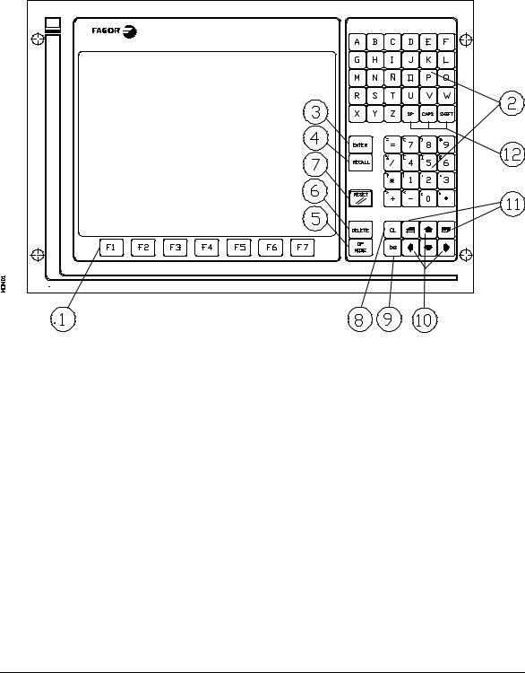
2. FRONT PANEL 8025/30 CNC
2.1. MONITOR/KEYBOARD FOR THE 8030 CNC
1.Function keys (SOFT-KEYS)
2.Alphanumeric keyboard for editing programs.
3. ENTER. Allows information to be entered in the CNC memory, etc.
4.RECALL. To access a program, a block within a program,etc.
5. |
OP MODE. Allows a list of operating modes to be displayed on the screen. It is a |
|
|
previous step to accessing any of them. |
|
6. |
DELETE. It allows deletion of a complete program or |
a block of the programme. |
|
Deletion of the graphic representation, etc. |
|
2 |
8025/8030 CNC OPERATING MANUAL |

7.RESET. To revert the CNC to the initial conditions and recognise new machine parameter values, decoded M functions, etc.
8.CL. To delete characters one by one during the editing process, etc.
9.INS. Key which allows characters to be inserted during the edition of a program block.
10. Arrow keys for moving cursor.
11. Page up and page down keys.
12.SP. Reserves a space between characters of a comment. CAPS. Allows characters to be edited in capitals.
SHIFT. Allows characters to be edited which are found on keys with double meaning.
8025/8030 CNC OPERATING MANUAL |
3 |
Loading...