


 Loading...
8040 CNC
REF. 0307
(SOFT M: 7.XX)
(SOFT M: 7.1X)
NEW FEATURES

8040 CNC
NEW FEATURES
(SOFT M: 7.XX)
(SOFT M: 7.1X)
Page 2 of 2

INDEX
Version 7.01 |
|
|
1 |
Detected errors .................................................................................................................. |
1 |
2 |
Sampling period ................................................................................................................. |
2 |
3 |
The meaningless zeros will not be displayed ..................................................................... |
2 |
4 |
Management of the new Sercos board .............................................................................. |
3 |
5 |
Key inhibiting codes for the monitors ................................................................................. |
3 |
6 |
New work languages .......................................................................................................... |
3 |
7 |
Load version without using an external microprocessor. ................................................... |
3 |
8 |
WINDNC improvements ..................................................................................................... |
4 |
9 |
Telediagnosis ..................................................................................................................... |
4 |
10 |
Improvements to the profile editor ...................................................................................... |
6 |
11 |
Modified variables .............................................................................................................. |
6 |
12 |
New variables ..................................................................................................................... |
7 |
13 |
New range of OEM subroutines. ........................................................................................ |
9 |
14 |
RPT instruction with program number definition ................................................................ |
9 |
15 |
Improved non-random tool magazine management .......................................................... |
9 |
16 |
Improved drive parameter management .......................................................................... |
10 |
17 |
User and OEM arithmetic parameters .............................................................................. |
10 |
18 |
Exponential type of leadscrew backlash peak ................................................................. |
10 |
19 |
Functions associated to machine safety .......................................................................... |
11 |
19.1 |
Limit the feedrate of the axes and the spindle speed ................................................ |
11 |
19.2 |
Cycle Start disabled by hardware errors ................................................................... |
12 |
19.3 |
Maximum spindle machining speed. ......................................................................... |
12 |
20 |
Axes (2) controlled by a drive ........................................................................................... |
13 |
21 |
Mandatory home search .................................................................................................. |
13 |
22 |
Change of active tool from the PLC ................................................................................. |
14 |
23 |
Synchronize a PLC axis with a CNC axis ........................................................................ |
14 |
24 |
Error register .................................................................................................................... |
15 |
25 |
Path JOG mode ............................................................................................................... |
15 |
26 |
Tool inspection ................................................................................................................. |
17 |
27 |
New instructions in the configuration language ................................................................ |
17 |
28 |
Improvements in tool compensation ................................................................................ |
18 |
29 |
Improvements in high speed machining ........................................................................... |
19 |
30 |
New graphics option ......................................................................................................... |
20 |
31 |
Improvement in the tool measuring cycle PROBE1 ......................................................... |
20 |
31.1 |
Measure or calibrate the tool length. ......................................................................... |
21 |
31.2 |
Measure or calibrate the radius of a tool. .................................................................. |
23 |
31.3 |
Measure or calibrate the tool radius and length. ....................................................... |
24 |
32 |
Oscilloscope function ....................................................................................................... |
26 |
32.1 |
Configuration ............................................................................................................. |
27 |
32.2 |
Scale / Offsets ........................................................................................................... |
32 |
32.3 |
Analysis ..................................................................................................................... |
33 |
32.4 |
Parameters ................................................................................................................ |
33 |
32.5 |
Actions ....................................................................................................................... |
34 |
32.6 |
Begin ......................................................................................................................... |
34 |
33 |
MC model. Execute a part-program ................................................................................. |
35 |
34 |
MC model. Maintain F, S y Smax on power up ................................................................ |
35 |
35 |
MC model. Messages and warnings ................................................................................ |
35 |
36 |
MC model. Tool calibration .............................................................................................. |
35 |
37 |
MC model. Cycle selection ............................................................................................... |
36 |
38 |
MC model. Auxiliary M functions in all the cycles ............................................................ |
37 |
39 |
MC model. Modifications in the tapping cycle .................................................................. |
38 |
40 |
MC model. Modifications in the Multiple milling and positioning cycles ........................... |
38 |
41 |
MC model. Icon indicating the available options .............................................................. |
38 |
42 |
MC model. Tool measurement and calibration ................................................................ |
39 |
8040 CNC
NEW FEATURES
Page i of ii

8040 CNC
NEW FEATURES
Version 7.11 |
|
|
1 |
Detected errors ................................................................................................................ |
43 |
2 |
New validation codes ....................................................................................................... |
45 |
3 |
Smooth stop in probing move (G75/G76) ........................................................................ |
45 |
4 |
Square-corner or round-corner machining when changing tool offset ............................. |
45 |
5 |
New management of the distance-coded reference mark (I0) ......................................... |
46 |
6 |
Improved look ahead ........................................................................................................ |
46 |
7 |
Leadscrew error compensation in both directions ............................................................ |
46 |
8 |
Parameters accessible from the oscilloscope or OEM subroutine ................................... |
47 |
8.1 |
Axis parameters that may be modified from the oscilloscope ................................... |
47 |
8.2 |
General parameters modifiable from the oscilloscope .............................................. |
47 |
8.3 |
Machine parameters modifiable from an OEM program ........................................... |
47 |
Page ii of ii

VERSION 7.01
1 Detected errors
NBTOOL Variable
The installation and programming manuals indicate that this variable is read-only from the CNC, PLC and DNC.
Actually, it is read-only from the CNC and DNC and it can only be used inside a tool-change subroutine.
OPMODE Variable
This variable also returns the following code:
25 Rapid simulation with S=0
56User parameter table
57OEM parameter table 117 Oscilloscope.
Probe canned cycle for surface measurement (PROBE 3)
The moving direction with K1 is as shown in this figure.
Connection of the KS50/55 adapter:
The installation manual describes how to use this adapter, but the correct connection is the following:
8040 CNC
NEW FEATURES
(SOFT M: 7.XX)
Detected errors
Page 1 of 48

8040 CNC
NEW FEATURES
(SOFT M: 7.XX)
Sampling period
X1 25-pin female SUB-D type (normal density) connector to connect the "Central Unit + Monitor".
X2 25-pin female SUB-D type (normal density) connector to connect the "Alphanumeric keyboard + Monitor".
X3 25-pin female SUB-D type (normal density) connector to connect the "Operator panel".
X4 3-pin male Phoenix connector, 7,62 mm pitch, to select the keyboard to be attended by the Central Unit.
Pin |
Value |
Meaning |
|
|
|
1 |
0V |
The CNC attends to the operator panel |
|
24V |
The CNC attends to the alphanumeric keyboard |
|
|
|
2 |
---- |
Not being used |
3 |
GND |
External power supply |
|
|
|
If connector X4 is not supplied with voltage, the CNC attends to the operator panel.
Main plane simulation
Page 2 of chapter 3 of the operating manual does not mention this type of simulation.
It only executes the movements corresponding to the axes that form the main plane.
It takes into account the tool radius compensation (functions G41,
G42) thus drawing the tool center path.
It sends the M, S, T functions to the PLC.
It starts the spindle, if programmed.
The axes move at maximum feedrate F0 regardless of the F that was programmed and it may be varied with the Feedrate Override switch.
2 Sampling period
From this version on, on the 8055/C and 8055i/C models that do not have the CPU turbo, it is possible to set a sampling period of 2 milliseconds g.m.p. “LOOPTIME (P72)”.
The following values may be allocated to plc.m.p. "CPUTIME (P26) that sets the time the System CPU dedicates to the PLC when programming a "LOOPTIME = 2 ms":
CPUTIME = 0 1 ms every 8 samplings, every 16 ms
CPUTIME = 1 1 ms every 4 samplings, every 8 ms
CPUTIME = 2 1 ms every 2 samplings, every 4 ms
By default 0
3 The meaningless zeros will not be displayed
From this version on, the data displayed on the screen (positions, feedrates, etc.) will not display the meaningless zeros to the left of the value. Example:
From this version on |
Z |
-4.210 |
Previous versions |
Z -00004.210 |
|
|
|
|
Page 2 of 48

4 Management of the new Sercos board
This software version is ready to work with the new Sercos boards, reference: 902103 and newer.
The "Hardware diagnosis" function shows these boards as "SERCOS816" because they carry the SERCON 816 chip.
5 Key inhibiting codes for the monitors
The inhibiting codes for softkeys F1 through F7 of monitors models such as “NMON-55-11-LCD” are:
F1 |
F2 |
F3 |
F4 |
F5 |
F6 |
F7 |
|
|
|
|
|
|
|
Bit 24 |
Bit 25 |
Bit 26 |
Bit 27 |
Bit 28 |
Bit 29 |
Bit 30 |
R508 |
R508 |
R508 |
R508 |
R508 |
R508 |
R508 |
|
|
|
|
|
|
|
|
|
|
|
|
|
|
6 New work languages
Basque and Russian are now available from this version on.
LANGUAGE (P122) Defines the work language
Possible values: |
|
|
|
|
|
0 |
English |
1 |
Spanish |
2 |
French |
3 |
Italian |
4 |
German |
5 |
Dutch |
6 |
Portuguese |
7 |
Czech |
8 |
Polish |
9 |
Mainland Chinese |
10 |
Basque |
11 |
Russian |
By default 0
7 Load version without using an external microprocessor.
This feature is available on 8040 CNC models whose identifying label shows "03 A" or later and whose software version is V07.01 or later.
It is not necessary to turn the CNC off and back on or actuate the external switch to update the software version, as indicated in section 2.2 of the Operating Manual.
To update the CNC software, proceed as follows:
•Remove the "Memkey Card" and insert the "Memory Card" that contains the software version to be updated.
•Access the Diagnosis mode - Software Configuration and press the [Load version] softkey.
The CNC will show the software updating stages and their status.
•When done updating it, remove the "Memory Card" that contains the software version and insert the "Memkey Card" back.
Note: • If the "[load version]" softkey is pressed but the Memory Card containing the software version is missing, the CNC will issue the relevant error message.
•The CNC cannot execute anything if it has the Memory Card that contains the software version.
8040 CNC
NEW FEATURES
(SOFT M: 7.XX)
Management of the
new Sercos board
Page 3 of 48
8040 CNC
NEW FEATURES
(SOFT M: 7.XX)
WINDNC improvements
8 WINDNC improvements
|
|
|
From this CNC version on and having WINDNC version V2.0 and the |
|
|
|
|
following, it is possible: |
|
|
|
|
• Select the work unit for CNC files Option (a). |
|
|
|
(a) |
Then indicate the desired work unit: Memory (b), Hard Disk (c) or |
|
|
|
|
Card A (d). |
|
(b) |
(c) |
(d) |
• From a PC, using the WINDNC application, copy from the CNC |
|
to the PC or vice versa, any file, program or table available in the |
||||
|
|
|
||
|
|
|
CARDA or hard disk. The available new tables are: |
OEP |
OEM arithmetic parameters |
USP |
USER arithmetic parameters |
DRS |
Spindle drive table |
DS2 |
Table of the Second Spindle drive |
DPX |
Table for the Auxiliary spindle drive |
DRX, DRY, Tables for axis drives
DRZ, DRU,
DRV, DRW,
DRA, DRB,
DRC
These tables are compatible with the tables that have been saved from the drive to a PC via serial line using WINDDS.
•Consult the table directory (machine parameters, zero offsets, magazine, tools, tool offsets, geometry, user parameter, OEM parameter, etc.).
•Read global and local arithmetic parameters individually using variables GUPn and LUP(a,b).
The installation and programming manuals describe how to use these variables.
•Having telediagnosis, display CNC screens at the PC in remote mode via serial line or via MODEM.
•Having telediagnosis, dial the telephone number associated with the modem at the PC.
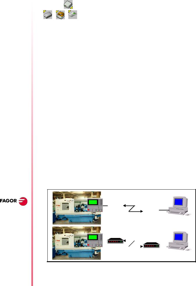
9 Telediagnosis
It may be used to govern and monitor the CNC status remotely through the RS232 serial line or using a modem through a telephone line.
CNC |
PC |
(RS232)
(RS232)
|
|
Módem |
||||||
CNC |
|
|
|
|
|
|
|
PC |
|
|
|
|
|
|
Módem |
||
|
|
|
|
|
|
|
|
|
|
|
|
|
|
|
|
|
|
LíneaTelephonetelefónlineca
Internet - RDSI
Page 4 of 48
The remote PC must have the WINDNC application version 2.00 or later installed in it and the CNC software version must be V07.01 or later.
CNC connection to the telephone line
It must be done through the RS232 serial line and using a modem that has RS232 serial line communication.
First, turn on the modem, then the CNC and then the remote PC, in that order.
PC connection to the telephone line
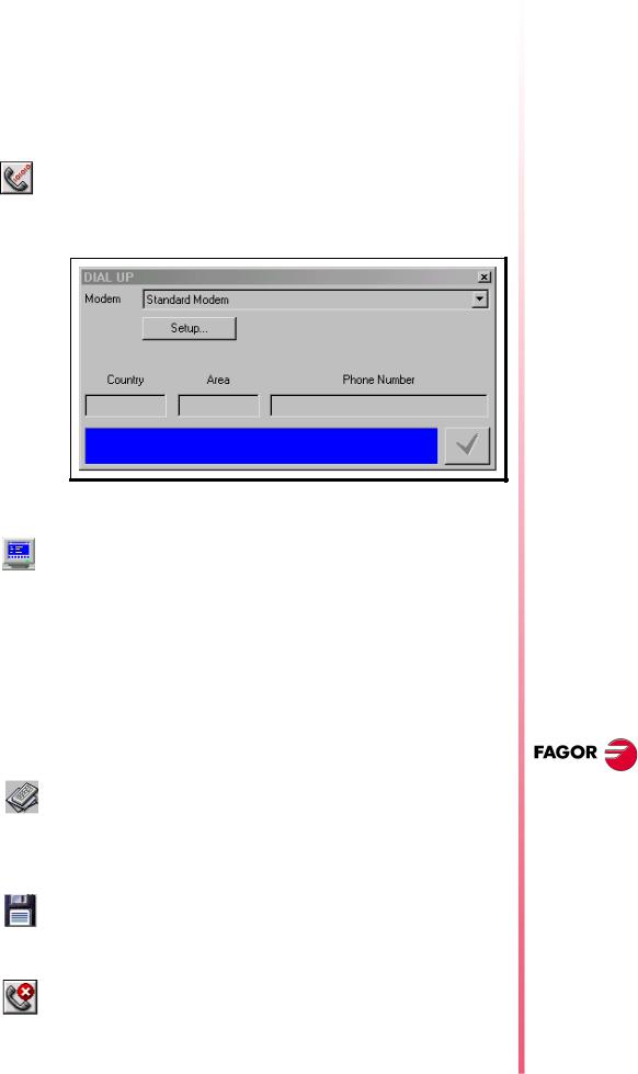
Connect the PC to the telephone line through a modem and execute the WINDNC application. Within the options for the serial line, select
(a)
option (a).
The application shows the following window. Indicate which modem is being used and the telephone number to dial.
PC-CNC communication (Telediagnosis)
Once the connection has been established (either via serial line or via modem), select the "telediagnosis" option (b) of the WINDNC
(b)
application.
From this moment on, the CNC may be governed either from its own keyboard or remotely from the PC keyboard.
•The PC will display the same information (screens) as the CNC.
•It is possible to access the different CNC modes, modify tables and parameters when knowing the password, simulate programs, etc.
•For safety reasons, it is not possible to move the axes of the machine or execute part-programs.
With the WINDNC application, it is also possible to send to the CNC
a file containing a keystroke sequence, option (c).
(c)
While in remote control mode, no other DNC command may be executed through the same serial line (for example the execution of an infinite program).
With option (d), it is possible to save into a BMP file a CNC screen
image that is being displayed.
(d)
End the communication (End telediagnosis)
To end the communication, select option (e) from those associated
to the serial line in the WINDNC application.
(e)
8040 CNC
NEW FEATURES
(SOFT M: 7.XX)
Telediagnosis
Page 5 of 48

8040 CNC
NEW FEATURES
(SOFT M: 7.XX)
Improvements to the profile editor
10 Improvements to the profile editor
The following improvements have been made:
It is possible to select the coordinate system of the work plane, axes and their direction.
The right window, under "Display Area", indicates whether the autozoom is on or not and the selected coordinate system.
It includes graphic data editing. Use the up-arrow and down-arrow keys to select the desired window and key in the desired value.
It is possible to modify rectangular and circular elements.
There are 2 new softkeys:
Save and continue
To save a profile without having to quit the session.
Undo
To undo the last modification.
On conversational models, MC and MCO, it indicates the number of the profile being edited.
11 Modified variables
HARCON It indicates, with bits, the CNC's hardware configuration.
The bit will be "1" when the relevant configuration is available.
From now on, bits 24, 25, 26 indicate the type of monitor and bits 27, 28 the CPU turbo board being used.
|
|
bit |
|
|
|
|
|
|
|
|
|
26,25,24 |
000 |
Color LCD Monitor |
|
|
|
001 |
Monochrome LCD monitor |
|
|
|
|
|
|
|
28,27 |
00 |
Turbo board at 25 Mhz |
|
|
|
01 |
Turbo board at 40 Mhz |
MPGn |
|
|
|
|
|
|
|
|
|
These variables, related to machine parameters, that until now were |
||||
MP(X-C)n |
read-only, from this version on, can be read and written from the |
|||
MPSn |
CNC in the following cases: |
|||
MPSSn |
• When they are executed inside an OEM program. |
|||
MPASn |
• When they are executed inside an OEM subroutine. |
|||
MPLCn |
|
|
|
|
To modify machine parameters from the PLC, an OEM subroutine containing the relevant variables must be executed using the CNCEX instruction.
In order for the CNC to assume the new values, one must operate according to the indicators associated with each machine parameter.
//It is necessary to press the keystroke sequence: "Shift - Reset" or turn the CNC off and back on.
/Just press Reset.
The rest of the parameters (those unmarked) will be updated automatically, only by changing them.
Page 6 of 48
12 New variables
Feedrate related variables
FREAL(X-C) Actual (real) X-C axis feedrate Is read-only from the CNC, DNC and PLC.
FTEO(X-C) Theoretical X-C axis feedrate Is read-only from the CNC, DNC and PLC.
Coordinate related variables
DPLY(X-C) "Coordinates of the selected axis" displayed on the screen Is readonly from the CNC, DNC and PLC.
DRPO(X-C) Position indicated by the X-C axis Sercos drive (Sercos variable PV51 or PV53 of the drive). Is read-only from the CNC, DNC and PLC.
GPOS(X-C)n p Programmed coordinate for a particular axis (X-C), in the indicated block (n) and program (p).
(P100 = GPOSX N99 P100)
It assigns to P100 the value of the coordinated programmed for the X axis in label N99 and located in program P100.
It Is read-only and it is only enabled at the CNC. Only programs located in RAM memory may be consulted.
•If the defined program number does not exist, it issues Error 69 "Program does not exist".
•If the defined block number does not exist, it issues error 1060 "undefined label".
•If the requested axis is not programmed in the indicated block, it returns the value: 100000.0000
Spindle related variables
DRPOS Position indicated by the Sercos drive of the spindle. Is read-only from the CNC, DNC and PLC.
SDRPOS Position indicated by the Sercos drive of the second spindle. Is readonly from the CNC, DNC and PLC.
FTEOS Theoretical spindle turning speed. Is read-only from the CNC, DNC and PLC.
SFTEOS Theoretical second spindle turning speed. Is read-only from the CNC, DNC and PLC.
Speed limit related variables
MDISL Maximum spindle machining speed. It is read-write from the PLC and read-only from DNC and CNC.
This variable is also updated with the programmed S value, in the following cases:
When programming "G92 S" in MDI mode
8040 CNC
NEW FEATURES
(SOFT M: 7.XX)
New variables
Page 7 of 48

8040 CNC
NEW FEATURES
(SOFT M: 7.XX)
New variables
When programming "G92 S" in ISO code in MC mode.
Variables related to Probe cycles
TIPPRB It indicates the PROBE cycle being executed at the CNC. Is readonly from the CNC, DNC and PLC.
TIPDIG It indicates the DIGIT cycle being executed at the CNC. Is read-only from the CNC, DNC and PLC.
PLC related variables
PLCMM(n) It permits reading modifying a single PLC mark (the PLCM variable permits reading or modifying 32 marks at once). It is read-write and it is only available from the CNC.
(PLCMM4 = 1)
It sets mark M4 to "1" and leaves the rest untouched
(PLCM4 = 1)
It sets mark M4 to "1" and the following 31 marks (M5, through M35) to "0"
Feedback related variables
ASIN(X-C) "A" signal of the CNC sinusoidal feedback for the X-C axis. Is readonly from the CNC, DNC and PLC.
BSIN(X-C) "B" signal of the CNC sinusoidal feedback for the X-C axis. Is readonly from the CNC, DNC and PLC.
ASINS "A" signal of the CNC sinusoidal feedback for the spindle. Is readonly from the CNC, DNC and PLC.
BSINS "B" signal of the CNC sinusoidal feedback for the spindle. Is readonly from the CNC, DNC and PLC.
SASINS "A" signal of the CNC sinusoidal feedback for the second spindle. Is read-only from the CNC, DNC and PLC.
SBSINS "B" signal of the CNC sinusoidal feedback for the second spindle. Is read-only from the CNC, DNC and PLC.
Variables related to the WGDRAW application
PANEDI Number of the screen created by the user or by the OEM using the WGDRAW application for diagnosis, consultation, work cycle, etc, that is being consulted. Is read-only from the CNC, DNC and PLC.
DATEDI Number of the screen element created using the WGDRAW application that is being consulted. Is read-only from the CNC, DNC and PLC.
Page 8 of 48

13 New range of OEM subroutines.
A new range of OEM subroutines has now been defined.
Available subroutine ranges:
General subroutines |
SUB 0001 - SUB 9999 |
|
|
OEM subroutines |
SUB 10000 - SUB 20000 |
|
|
Although OEM subroutines are treated like the general ones, the have the following restrictions:
•They can only be defined in OEM programs, having the [O] attribute. Otherwise, it shows error 63 "Program subroutine number between 1 and 9999.".
•If the subroutine to be executed using CALL, PCALL or MCALL is an OEM subroutine and it is located in a program that does not the [O] attribute, it will issue Error 1255 "Subroutine restricted to OEM program".
14 RPT instruction with program number definition
From this version on, the RPT instruction can execute a portion of the same program or of the indicated program.
(RPT N(expression), N(expression), P(expression))
The new parameter "P" indicates the number of the program located in RAM memory containing the two blocks defined by the N labels.
•If parameter "P" is not defined, the CNC interprets that the portion to be repeated is located in the same program.
•If the defined program number does not exist, it issues Error 69 "Program does not exist".
Warning:
i |
Since the RPT instruction does not interrupt block preparation or tool |
compensation, it may be used when using the EXEC instruction and |
|
while needing to maintain tool compensation active. |
8040 CNC
15 Improved non-random tool magazine management
When the tool changer is configured as non-random, the tools must be placed in the tool magazine table in the pre-established order (P1 T1, P2 T2, P3 T3, P4 T4, etc.).
With this improvement, it is possible to assign several tools to each tool position.
TOOLMATY (P164) This g.m.p. is taken into account when using a non-random tool magazine. It indicates how many tools may be assigned to each turret position.
0One tool per position
1Several tools per position.
By default 0
NEW FEATURES
(SOFT M: 7.XX)
New range of OEM subroutines.
Page 9 of 48

8040 CNC
NEW FEATURES
(SOFT M: 7.XX)
Improved drive parameter management
16 Improved drive parameter management
From this version on, it also possible to save and load into a peripheral device or PC the drive parameter tables via Sercos serial line.
For that, select the parameter page of the desired drive at the CNC and press the relevant softkey.
A file saved from the CNC via WINDNC may be loaded into the drive via DDSSETUP and vice versa.
17 User and OEM arithmetic parameters
There are now two new ranges of global arithmetic parameters.
User parameters |
Range: P1000 |
- P1255. |
OEM parameters |
Range: P2000 |
- P2255 |
For compatibility with previous versions, global arithmetic parameters P100-P299 are maintained and may be used by the user, by the OEM and by the CNC cycles.
There are now 2 new tables of global arithmetic parameters.
|
Arithmetic parameter tables available: |
|
GUP |
Global parameters |
P100-P299 |
|
|
|
USP |
User parameters |
P1000-P1255 |
|
|
|
OEP |
OEM parameters |
P2000 - P2255 |
|
|
|
Changing an OEM parameter requires an OEM password.
OEM parameters and subroutines having OEM parameters may only be written in OEM programs having the [O] attribute.
On the MC and MCO models, when using OEM parameters in the configuration programs, these programs must have the [O] attribute. If they don't, an error will be issued when editing a user cycle that refers to OEM parameters in write mode.
General machine parameters “ROPARMIN” and “ROPARMAX” may be used to protect any global parameter (user and OEM included) against being written.
There is no restriction to read these parameters.
18 Exponential type of leadscrew backlash peak
The additional command pulse used to make up for the possible leadscrew backlash in movement reversals may be rectangular or exponential.
If the duration of the rectangular pulse is adjusted for low speed, it could be excessive for high speed or insufficient for low speed when adjusted for high speed.
In this cases, it is recommended to use the exponential type that applies a strong pulse at the beginning and decreases in time.
Page 10 of 48

Bit 16 of g.m.p. “ACTBAKAN (P144)” indicates the backlash peak being used.
0rectangular leadscrew backlash peak
1exponential type of leadscrew backlash peak
By default 0
A finer tuning of the leadscrew backlash consists in testing the circle geometry and watch for internal peaks when changing quadrants (left figure). In these cases, it is recommended to set bit 15 of g.m.p. “ACTBAKAN (P144)” to "1" to eliminate the internal peaks.
Under these conditions, the CNC eliminates the leadscrew backlash peak as soon as it detects a movement reversal. If the internal peaks are not eliminated, adjust the leadscrew backlash compensation better.
ACTBAKAN (P144) It has 16 bits counted from left to right.
bit |
Function |
|
bit |
Function |
|
|
|
|
|
1 |
|
|
9 |
|
|
|
|
|
|
2 |
|
|
10 |
|
|
|
|
|
|
3 |
Additional pulse with G2 |
|
11 |
|
/ G3 |
|
|
||
|
|
|
|
|
|
|
|
|
|
4 |
|
|
12 |
|
|
|
|
|
|
5 |
|
|
13 |
|
|
|
|
|
|
6 |
|
|
14 |
|
|
|
|
|
|
|
|
|
|
It minimizes internal peaks |
7 |
|
|
15 |
detected with the circle |
|
|
|
|
geometry test |
|
|
|
|
|
8 |
|
|
16 |
Exponential leadscrew |
|
|
backlash peak |
||
|
|
|
|
|
|
|
|
|
|
By default, all bits are set to "0".
19 Functions associated to machine safety
19.1 Limit the feedrate of the axes and the spindle speed
It is possible to limit the feedrate of the axes and the spindle turning speed.
FLIMIT (P75) The a.m.p. "FLIMIT" sets the maximum feedrate for each axis and SLIMIT (P66) the s.m.p. "SLIMIT" sets the maximum turning speed for each
spindle.
FLIMITAC (M5058) When the PLC sets this signal high, it limits the feedrate of all the axes. It does not let any feedrate to exceed the value set by the corresponding a.m.p. "FLIMIT (P75)" .
SLIMITAC (M5059) When the PLC sets this signal high, it limits the speed of all the spindles. It does not let any feedrate to exceed the value set by the corresponding s.m.p. "SLIMIT (P66)" .
The limitation is applied in all work modes, including the PLC channel. When the mark is high, the CNC applies the limitation and when going low, it restores the programmed F or S.
8040 CNC
NEW FEATURES
(SOFT M: 7.XX)
Functions associated to machine safety
Page 11 of 48

8040 CNC
NEW FEATURES
(SOFT M: 7.XX)
Functions associated to machine safety
When the spindle moves with PLCCNTL, the spindle limitation is ignored.
19.2 Cycle Start disabled by hardware errors
If when pressing the Cycle-Start key, a hardware error is detected (Sercos board error, CAN board error, etc.), the CNC issues the corresponding error message and does not allow executing or simulating the program.
19.3 Maximum spindle machining speed.
To limit the spindle speed, use the MDISL variable associated with speed limits. It is read-write from the PLC and read-only from DNC and CNC.
This variable is also updated with the programmed S value, in the following cases:
•When programming "G92 S" in MDI mode
•When programming "G92 S" in ISO code in MC mode.
•In MC mode, when a new speed limit is defined in the "SMAX" field.
The speed limits entered via CNC, PLC (PLCSL) and DNC (DNCSL) keep the same functionality and priority unaffected by the new MDISL variable; in other words, the CNC keeps limiting the spindle speed like until now.
In order to comply with the safety regulation, it is recommended to manage from the PLC the variables associated with speed limits as shown in the following example:
•A new part-program cannot be executed without previously entering the speed limit. Otherwise, a message will be displayed.
If the program is executed again, the limit does not have to be entered again, it is only required when executing the program for the first time.
•While executing a program if a new limit is entered in MDI, the new one will replace the previous one.
•In independent MC cycles it is not required to enter the SMAX because it is already defined in each cycle.
•If the program being executed already has a G92S, it will be validated only if it is smaller than the one programmed in MDI.
•When having two main spindles, the speed limit entered will be valid for both.
PRG |
|
REA |
|
()=CNCRD(OPMODA,R100,M1000) |
; Reading of OPMODA |
B0R100 AND INCYCLE = M100 |
; Indicator of program in execution |
; |
|
DFU M100 |
; At the beginning of the execution |
= CNCRD(PRGN,R101,M1000) |
; reads the program in execution |
= CNCRD(MDISL,R102,M1000) |
; and the S limitation from MDI |
; |
|
M100 |
; During the execution |
= CNCRD(PRGSL,R103,M1000) |
; and the S limitation from CNC |
; |
|
M100 AND CPS R101 NE R201 |
; If new program in execution |
= M101 |
; activates mark M101 |
; |
|
M100 AND CPS R101 EQ R201 |
; If same program in execution |
Page 12 of 48

= M102 |
; activates mark M102 |
; |
|
M101 |
; If new program in execution |
AND CPS R102 EQ 0 |
; and the "S" has not been limited from MDI |
= ERR10 |
; Error 10: "The S has not been limited from |
|
MDI" |
; |
|
M101 |
; If new program in execution |
AND CPS R102 NE 0 |
; and the "S" has been limited from MDI |
= MOV R101 R201 |
; it copies the number of the program in |
|
execution |
= MOV R102 R202 |
; and the S limitation from MDI |
; |
|
M102 |
; If same program in execution |
AND CPS R102 NE 0 |
; and the "S" is limited again from MDI |
= MOV R102 R202 |
; it copies the S limitation from MDI |
; |
|
M100 |
; If program in execution |
AND CPS R202 LT R103 |
; and "S" limitation from MDI < "S" limitation |
|
from CNC |
= CNCWR(R202,PLCSL,M1000) |
; Applies "S" limitation from the PLC with the |
|
value set in MDI |
; |
|
M100 |
; If program in execution |
AND CPS R202 GT R103 |
; and "S" limitation from MDI > "S" limitation |
|
from CNC |
= CNCWR(R210,PLCSL,M1000) |
; It does not limit "S" from PLC (R210=0) |
; |
|
DFD M100 |
; At the end of execution |
= CNCWR(R210,PLCSL,M1000) |
; it cancels "S" limitation from the PLC |
= CNCWR(R210,MDISL,M1000) |
; and it resets the MDISL variable |
; |
|
END |
|
20 Axes (2) controlled by a drive
Until this version, when having 2 axes controlled by a single drive, the polarity of the analog output (command sign) always corresponded to that of the main axis.
From this version on, since sometimes the turning direction of the two axes may be different, the sign of the command for each axis will taken into account [the one set by a.m.p “LOOPCHG (P26)”].
Warning
This new version is not compatible with previous versions.
On machines having axes controlled by a single drive the secondary axis might run away.
Before installing the new software, make sure that the a.m.p. "LOOPCHG (P26)" of the associated axis has the same value as that of the main axis.
21 Mandatory home search
The CNC forces a home search on an axis by setting the relevant
REFPOIN* mark low in the following cases:
•On CNC power-up
•After executing SHIFT RESET
•When the feedback is direct through the axes board and a feedback alarm occurs.
8040 CNC
NEW FEATURES
(SOFT M: 7.XX)
Axes (2) controlled by a drive
Page 13 of 48
8040 CNC
NEW FEATURES
(SOFT M: 7.XX)
Change of active tool from the PLC
•When losing feedback count via Sercos due to broken communication. Difference greater than 10 microns (0.00039") or 0.01º
•When changing machine parameters that affect the memory distribution, for example: number of axes.
In all these cases, a home search must be carried out so the signal is set back high.
22 Change of active tool from the PLC
If the tool change process is interrupted, the values of the tool magazine table and active tool may not reflect the machine's reality.
To update the tool table, variables TOOL, NXTOOL, TOD and NXTOD that until now were read-only are now read-write from the PLC as long as a block or a part-program is not being executed or simulated.
TOOL |
Number of the active tool |
|
|
NXTOOL |
Number of the next tool that is selected, but waiting for the |
|
execution of an M06 to become active. |
|
|
TOD |
Number of the active tool offset |
|
|
NXTOD |
Number of the offset of the next tool that is selected, but |
|
waiting for the execution of an M06 to become active. |
|
|
This way, it is possible to resume the tool change from the PLC and redefine the tool table according to their positions using the TMZT variable.
To allocate a magazine position to the tool that is considered active by the CNC and is physically in the tool magazine, proceed as follows:
1.Cancel the tool, TOOL=0 and TOD=0
2.Assign the relevant position using the TMZT variable.
When trying to write in variables TOOL, NXTOOL, TOD and NXTOD check the OPMODA variable to make sure that no block or partprogram is being executed or simulated. The following bits must be at "0".
OPMODA
bit 0 Program in execution bit 1 Program in simulation
bit 2 Block in execution via MDI, JOG bit 8 Block in execution via CNCEX1
23 Synchronize a PLC axis with a CNC axis
To synchronize an axis of the PLC channel with another one of the CNC channel (main channel), set a.m.p. SYNCHRO (P3) of the PLC axis indicating which axis it must synchronize with.
Axis synchronization is carried out from the PLC by activating the general input "SYNCHRO" of the axis to be coupled as slave (PLC axis).
To assure that both axes are stopped when they are being synchronized, we suggest:
Page 14 of 48

•To execute a special M function at the CNC so the PLC executes another M function in the PLC channel and activates the general input "SYNCHRO".
•The M function of the main channel must not end until the PLC's M function execution is completed and the ENABLE signal of the slave axis is set high.
Once both axes are synchronized, it won't be possible to program movements of the PLC axis. Otherwise, error 1099 will be issued: "Do not program a slaved axis".
During synchronization, it does not check whether the PLC axis gets in position or not. For this reason:
•The logic output "ENABLE" of the PLC axis is activated (allowing motion).
•The logic output "INPOS" of the PLC axis is deactivated (the axis is NOT in position).
•General input "INHIBIT" of the PLC axis is ignored, thus not being possible to prevent it from moving.
•The execution of the movement of the synchronized slave axis cannot be aborted even by activating the general input "PLCABORT".
If an error occurs canceling the "ENABLE" logic outputs of all the axes, it also cancels the synchronization.
To end synchronization, cancel the "SYNCHRO" general input of the
PLC axis.
To assure that the PLC axis recovers its position after the synchronization, it is recommended to use other 2 special M functions, one at the CNC and another one at the PLC.
24 Error register
The "CNC" screen of the "STATUS" mode offers the softkey: [BB].
Pressing this softkey displays the error history indicating the error number and when it occurred.
This information is very useful to the service technician. Pressing the [SAVE] softkey requests the number of the CNC program to store that information.
If the service department asks you for that program, transfer it to a
PC via DNC and send it to the corresponding address via internet.
25 Path JOG mode
It is similar to the "Path Handwheel" mode.
The "Path Handwheel" mode acts at the Handwheel position of the selector switch whereas the "Path JOG" acts at the continuous and incremental jog positions of the selector switch.
"Path JOG" may be used to act upon the jog keys of an axis to move both axes of the plane at the same time for chamfering (straight sections) and rounding (curved sections).
The CNC assumes as "Path JOG" the keys associated with the X axis.
8040 CNC
NEW FEATURES
(SOFT M: 7.XX)
Error register
Page 15 of 48

8040 CNC
This feature must be managed from the PLC.
To turn on or off the "Path JOG" work mode, use CNC logic input “MASTRHND” M5054,
M5054 = 0 "Path JOG" function off.
M5054 = 1 "Path JOG" function on.
To indicate the type of movement, use CNC logic input “HNLINARC” M5053
M5053 = 0 Linear Path
M5053 = 1 Circular path.
For a linear path, indicate the path angle in the MASLAN variable (value in degrees between the linear path and the first axis of the plane)
For an arc, indicate the arc center coordinates in the MASCFI, MASCSE variables (for the first and second axes of the main plane)
Variables MASLAN, MASCFI and MASCSE may be read and written from the CNC, DNC and PLC.
NEW FEATURES
(SOFT M: 7.XX)
Path JOG mode
Operation
When pressing one of the associated keys, X+ and X-, the CNC acts as follows:
Selector |
Path JOG |
Type of movement |
|
Switch |
|
|
|
Position |
|
|
|
|
OFF |
Only the axis and in the indicated |
|
|
direction |
||
Continuous |
|
||
|
|
||
ON |
Both axes in the indicated direction along |
||
|
|||
|
the indicated path |
||
|
|
||
|
|
|
|
|
OFF |
Only the axis, the selected distance and |
|
|
in the indicated direction |
||
Incremental |
|
||
|
|
||
ON |
Both axes, the indicated distance and |
||
|
|||
|
direction, but along the indicated path |
||
|
|
||
|
|
|
|
Handwheel |
|
It ignores the keys. |
|
|
|
|
The rest of the keys always operate the same way regardless of whether the "Path JOG" function is on or off. It only moves the selected axis and in the indicated direction.
Considerations
It assumes as axis feedrate the one selected in JOG mode and it is affected by the override. If F0 is selected, it assumes the one indicated by a.m.p. “JOGFEED (P43)”. The [Rapid] key is ignored.
The movements in "Path JOG" observe the travel limits and zone boundaries
The movements in "Path JOG" may be aborted:
•By pressing the [CYCLE STOP] key
•By selecting one of the handwheel positions of the JOG selector switch.
Page 16 of 48
•By setting the general logic input “MASTRHND (M5054)” =0.
•Setting the general logic input “\STOP (M5001)”=0.
26 Tool inspection
The tool inspection mode now offers a new option: "Modify Offsets". This window shows (at the top) a help graphic and the tool fields that can be edited.
When editing the active tool, it is possible:
To modify the I and K data.
Select another tool for calibration (T xx Enter).
When NOT editing the active tool, it is possible:
To modify the I, K and D data.
Select another tool for calibration (T xx Enter).
The I and K values The values entered in the I, K fields are incremental, they are added to the ones already in the table. The "I" data is given in diameter.
The new g.m.p. “MAXOFFI (P165)” and “MAXOFFK (P166)” indicate the maximum value that may be entered in each field. When trying to enter a greater value, the relevant message will be displayed.
Warning
To assume the new I and K values, select the tool again.
27 New instructions in the configuration language
The new token "UNMODIFIED" of the configuration language indicates that the associated element must not take the editing focus.
;(UNMODIFIED) It is programmed as a prefix of the instructions
;(W1=GUP100)
It may be used to associate the "W1" data with the value of a global parameter, variable or resource of the PLC and the "W1" element is assigned the editing focus.
;(AUTOREFRESH W6=FLWEX)
It refreshes (updates) the value of the graphic element W6 and it assigns the editing focus to it.
The resulting new instructions are:
;(UNMODIFIED W1=GUP170)
It associates the "W" data with the value of a global parameter, variable or resource of the PLC, but the "W1" element does not take the editing focus.
;(UNMODIFIED AUTOREFRESH W6=FLWEX)
It refreshes (updates) the value of the graphic element W6 but it does not take the editing focus.
8040 CNC
NEW FEATURES
(SOFT M: 7.XX)
Tool inspection
Page 17 of 48
8040 CNC
NEW FEATURES
(SOFT M: 7.XX)
Improvements in tool compensation
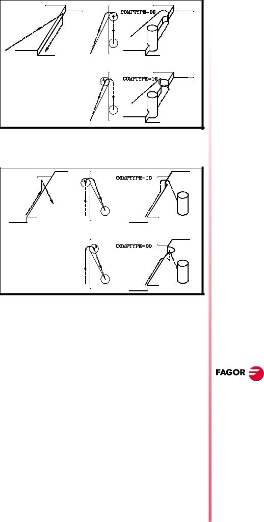
28 Improvements in tool compensation
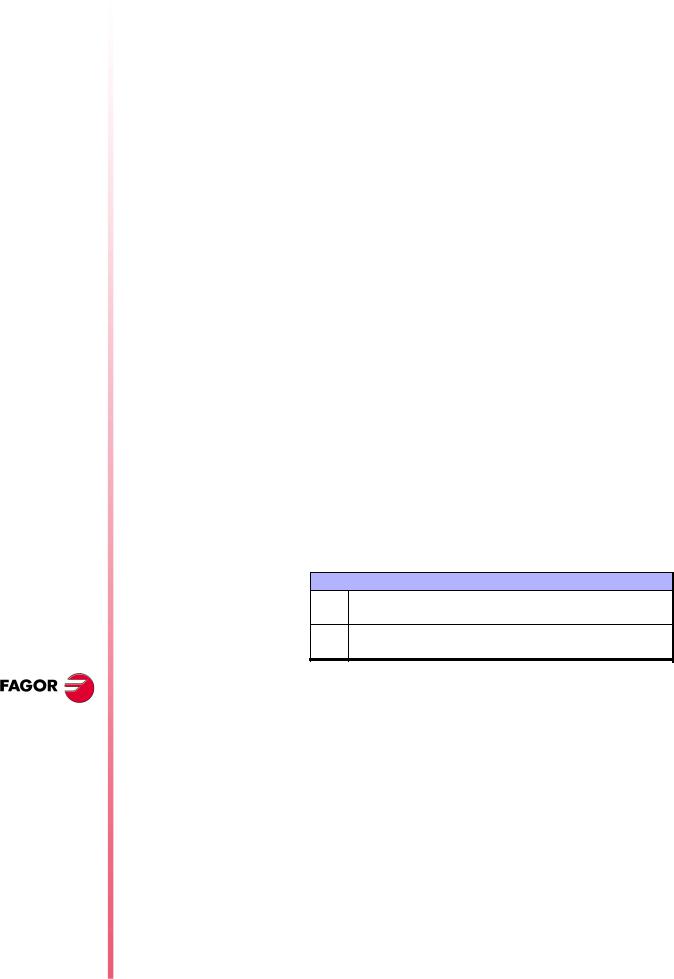
COMPTYPE (P74) From this version on, this g.m.p. has two digits.
The units set the beginning and end of radius compensation applied by the CNC (like it was before).
x0 It approaches the starting point going around the corner x1 it goes directly perpendicular to the point (without going
around the corner)
COMPTYPE= x0 |
COMPTYPE= x1 |
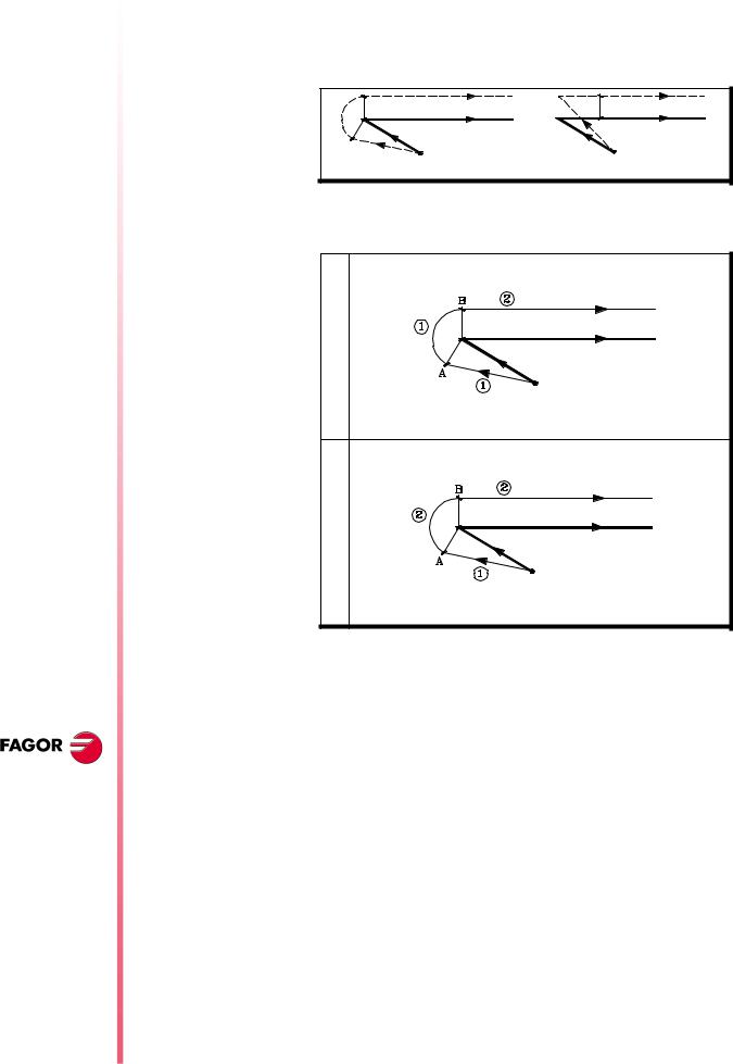
The tens indicate whether the additional block of the compensation is executed at the end of the current block or at the beginning of the next block with compensation.
00It is executed at the end of the current block (like in previous versions).
Executing block by block (single block mode), the first movement ends at point "B".
10It is executed at the beginning of the next block with compensation
Executing block by block (single block mode), the first movement ends at point "A".
By default COMPTYPE=00
When the beginning or end of the compensation takes place to a different plane (there is an intermediate vertical movement) and at an angle greater than 270º it is recommended to check the CNC's behavior as shown next:
At the beginning of the compensation, the tool should be positioned before penetrating into the part. The additional block must be
Page 18 of 48
executed in the upper plane and therefore together with the first block “COMPTYPE=00”.
At the end of the compensation, the tool should withdraw from the part without penetrating into it. The additional block must be executed in the upper plane and therefore together with the second block “COMPTYPE=10”.
29 Improvements in high speed machining
The number of blocks analyzed in advance (look-ahead) has been increased. From 50 blocks to 75.
The extreme cases have been improved, such as small blocks (of a few microns) in order to machine faster and more smoothly.
Jerk control can now be applied in Look-ahead, g.m.p. “JERKACT (P160) and TLOOK (P161)”.
Using Jerk in Look-ahead, a trapezoidal acceleration profile is applied with a ramp slope equivalent to the maximum jerk of the axis.
The maximum jerk depends on the value assigned to a.m.p. “JERKLIM (P67)” of that axis and of the axes involved in the programmed path.
JERKACT (P160) This parameter has 16 bits counted from left to right.
Bit 16 indicates whether to apply Jerk control in Look-ahead or not.
(0) Not applied.
8040 CNC
NEW FEATURES
(SOFT M: 7.XX)
Improvements in high speed machining
Page 19 of 48

8040 CNC
(1) Applied.
By default 0 (not applied)
If "Jerk Control in look ahead" has been selected, the CNC analyzes the a.m.p “JERKLIM (P67)” of each axis. During look-ahead, the CNC assumes, for the axes with “JERKLIM (P67)=0”, the value suggested in that parameter.
TLOOK (P161) Real block processing time for look-ahead.
If assigned a value smaller than the real one, the machine will vibrate and if assigned a value greater than the real one the machining slows down.
Possible values |
Integers between 0 and 65535 ms |
|
By default 0 |
This value is calculated as follows:
Execute, in G91 and G51 E0.1, a program with many small blocks, at least 1000. For example: “X0.01 Y0.01 Z0.01”.
Measure the program execution time, making sure that the machine does not vibrate. Divide the execution time by 1000 (or the number of blocks executed) and assign the resulting value, in microseconds, to g.m.p. "TLOOK (P161)".
We recommend the use of the oscilloscope function and verify that the internal variable VLOOKR remains constant which means that there is no vibration.
30 New graphics option
GRAPHICS (P16) New value (4) for g.m.p. GRAPHICS.
It is similar to "0" value (Mill model graphics) but with different XY line graphics.
NEW FEATURES
(SOFT M: 7.XX)
New graphics option
Page 20 of 48
|
|
|
|
|
|
|
|
|
|
|
|
|
|
|
|
|
|
|
|
|
|
|
|
GRAPHICS=0 |
|
GRAPHICS=4 |
|||
|
|
|
|
|
|
It is available when having Power PC.
31 Improvement in the tool measuring cycle PROBE1
In previous version, this cycle only calibrated the length of the tool (see section 12.3 of the programming manual).
From this version on, it may be used:
•To calibrate the tool length.
•To calibrate the tool radius.
•To calibrate the tool radius and length.
•Measure the tool length wear.
•Measure the tool radius wear.
•Measure the tool radius wear and length wear.
The programming cycle for the PROBE1 cycle is:
(PROBE 1, B, I, F, J, K, L, C, D, E, S, M, C, N, X, U, Y, V, Z, W)
Parameters X, U, Y, V, Z, W
They are optional parameters that are not usually necessary.
On certain machines, due to lack of mechanical positioning repeatability of the probe's, the probe must be calibrated before each tool calibration.
Instead of redefining machine parameters PRBXMIN, PRBXMAX, PRBYMIN, PRBYMAX, PRBZMAX, PRBZMIN every time the probe is calibrated, those coordinates may be indicated in variables X, U, Y, V, Z, W, respectively.
The CNC does not modify the machine parameters and only takes into account the coordinates indicated in X, U, Y, V, Z, W during this calibration.
If any of the X, U, Y, V, Z is left out, the CNC takes the value assigned to the corresponding machine parameter.
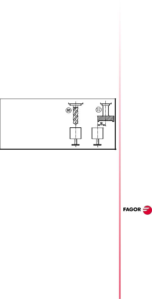
31.1 Measure or calibrate the tool length.
Parameter "I" defines where the measurement or calibration will be carried out:
I0 On the tool shaft.
I1 On the tool tip.
If not programmed, the canned cycle takes the value I0 (on the tool shaft).
8040 CNC
Measure or calibrate the tool length on its shaft.
It is carried out with the spindle stopped. It is useful for drilling tools, ball end-mills, or tools whose diameter is smaller than the probe's probing surface.
Calibration format:
(PROBE 1, B, I0, F, J0, X, U, Y, V, Z, W)
Format for wear measurement:
(PROBE 1, B, I0, F, J1, L, C, X, U, Y, V, Z, W)
B |
Safety distance, with positive value greater than "0". |
|
|
|
|
I0 |
Measure or calibrate the tool length on its shaft. |
|
|
|
|
F |
Probing feedrate, in mm/min. or in inches/min. |
|
|
|
|
J |
J0 = Calibration; J1 = Measurement |
|
|
|
|
L |
Maximum length wear permitted (with J1 and when using tool |
|
life monitoring). |
||
|
||
|
|
|
|
Behavior when exceeding the maximum wear allowed (L other |
|
|
than 0). |
|
C |
C0 = Interrupts the execution for the user to select another tool. |
|
|
C1 = The cycle replaces the tool with another one of the same |
|
|
family. |
|
|
|
|
X...W |
Optional |
|
|
|
Parameters J, L, C are optional. If not programmed, the following values are assumed:
NEW FEATURES
(SOFT M: 7.XX)
Improvement in the tool measuring cycle PROBE1
Page 21 of 48
8040 CNC
NEW FEATURES
(SOFT M: 7.XX)
Improvement in the tool measuring cycle PROBE1
J0 (calibration). L0 (the tool is not rejected due to wear). C0 (interrupts the execution for the user to select another tool)
Measure or calibrate the tool length on its tip.
It may be carried out either with the spindle stopped or turning the in the programmed direction (opposite to the cutting direction) It is useful for calibrating tools with several cutting edges or tools whose diameter is greater than the probe's probing surface.
Calibration format:
(PROBE 1, B, I1, F, J0, D, S, N, X, U, Y, V, Z, W)
Format for wear measurement:
(PROBE 1, B, I1, F, J1, L, D, S, C, N, X, U, Y, V, Z, W)
B Safety distance, with positive value greater than "0".
I1 Measure or calibrate the tool length on its tip.
F Probing feedrate, in mm/min. or in inches/min.
J J0 = Calibration; J1 = Measurement
L
Maximum length wear permitted (with J1 and when using tool life monitoring).
D
Radius or distance referred to the tool shaft being probed. If not programmed, it is done on the tip
Tool turning speed and direction. Select the opposite of the
Scutting direction (positive sign if M3 and negative if M4) With S0, calibration with spindle stopped.
Behavior when exceeding the maximum wear allowed (L other than 0)
CC0 = Interrupts the execution for the user to select another tool. C1 = The cycle replaces the tool with another one of the same
family.
Number of cutting edges to be measured. If N0, one
N
measurement.
To measure each cutting edge when the spindle has feedback and s.m.p. M19TYPE (P43) =1.
X...W Optional
Parameters J, L, D, S, C, N are optional. If not programmed, the following values are assumed:
J0 (calibration). L0 (the tool is not rejected due to wear). D= tool radius (probing is carried out on the tip). S0 (spindle stopped). C0 (interrupts the execution for the user to select another tool). N0 (the cutting edges are not measured separately).
Once the calibration cycle has ended
It updates global arithmetic parameter P299 and assigns the measured length to the tool offset selected in the tool offset table.
P299 = measured length - previous length (L+K)
L = measured length
K |
= 0 |
If the dimension of each cutting edge was requested, "N" parameter, the measured values are assigned to global arithmetic parameters P271 and on.
Once the wear measuring cycle has ended
When using tool life monitoring, it compares the measured value with the theoretical length assigned in the table.
Page 22 of 48

If the maximum allowed is exceeded, it issues a "tool rejected" message and acts as follows:
C0 It interrupts the execution for the user to select another tool.
The cycle replaces the tool with another one of the same family.
C1
It sets the "rejected tool " indicator (status = R)
It activates the general logic output PRTREJEC (M5564)
If the measuring difference does not exceed the maximum allowed or tool life monitoring is not available:
•It updates global arithmetic parameter P299 and the length wear value of the tool offset selected in the tool offset table.
P299 = measured length - theoretical length (L)
L = theoretical length (it maintains the previous value).
K = measured length - theoretical length (L) [New wear value]
If the dimension of each cutting edge was requested, "N" parameter, the measured values are assigned to global arithmetic parameters P271 and on.
31.2 Measure or calibrate the radius of a tool.
It may be carried out either with the spindle stopped or turning the in the programmed direction (opposite to the cutting direction)
Calibration format:
(PROBE 1, B, I2, F, J0, K, E, S, N, X, U, Y, V, Z, W)
Format for wear measurement:
(PROBE 1, B, I2, F, J1, K, E, S, M, C, N, X, U, Y, V, Z, W)
B Safety distance, with positive value greater than "0".
I2 Measure or calibrate the radius of a tool.
F Probing feedrate, in mm/min. or in inches/min.
J J0 = Calibration; J1 = Measurement
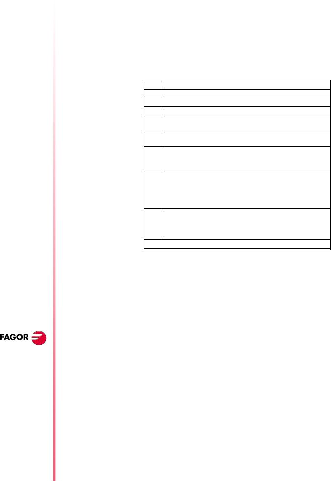
K
Probe side used.
K0 (X+ side), K1 (X- side), K2 (Y+ side), K3 (Y- side).
Distance referred to the theoretical tool tip being probed. It is very useful with cutters whose bottom is not horizontal.
E
Tool turning speed and direction. Select the opposite of the
Scutting direction (positive sign if M3 and negative if M4) With S0, calibration with spindle stopped.
M
Maximum radius wear permitted (with J1 and when using tool life monitoring).
Behavior when exceeding the maximum wear allowed (M other than 0).
CC0 = Interrupts the execution for the user to select another tool. C1 = The cycle replaces the tool with another one of the same
family.
Number of cutting edges to be measured. If N0, one
N
measurement.
To measure each cutting edge when the spindle has feedback and s.m.p. M19TYPE (P43) =1.
X...W Optional
Parameters J, E, S, M, C, N are optional. If not programmed, the following values are assumed:
8040 CNC
NEW FEATURES
(SOFT M: 7.XX)
Improvement in the tool measuring cycle PROBE1
Page 23 of 48

8040 CNC
NEW FEATURES
(SOFT M: 7.XX)
Improvement in the tool measuring cycle PROBE1
J0 (calibration). E0. S0 (spindle stopped). M0 (the tool is not rejected due to wear). C0 (interrupts the execution for the user to select another tool). N0 (the cutting edges are not measured separately).
Once the calibration cycle has ended
It updates global arithmetic parameter P298 and assigns the measured radius to the tool offset selected in the tool offset table.
P298 = measured radius - previous radius (R+I)
R = measured radius
I |
= 0 |
If the dimension of each cutting edge was requested, "N" parameter, the measured values are assigned to global arithmetic parameters P251 and on.
Once the wear measuring cycle has ended
When using tool life monitoring, it compares the measured value with the theoretical radius assigned in the table.
If the maximum allowed is exceeded, it issues a "tool rejected" message and acts as follows:
C0 It interrupts the execution for the user to select another tool.
The cycle replaces the tool with another one of the same family.
C1
It sets the "rejected tool " indicator (status = R)
It activates the general logic output PRTREJEC (M5564)
If the measuring difference does not exceed the maximum allowed or tool life monitoring is not available:
•It updates global arithmetic parameter P298 and the radius wear value of the tool offset selected in the tool offset table.
P298 = measured radius - theoretical radius (R)
R = theoretical radius (it maintains the previous value).
I = measured radius - theoretical radius (R) [New wear value]
If the dimension of each cutting edge was requested, "N" parameter, the measured values are assigned to global arithmetic parameters P271 and on.
31.3 Measure or calibrate the tool radius and length.
It may be carried out either with the spindle stopped or turning the in the programmed direction (opposite to the cutting direction)
Calibration format:
(PROBE 1, B, I3, F, J0, K, D, E, S, N, X, U, Y, V, Z, W)
Format for wear measurement:
(PROBE 1, B, I3, F, J1, K, L, D, E, S, M, C, N, X, U, Y, V, Z, W)
B Safety distance, with positive value greater than "0".
I3 Measure or calibrate the tool radius and length.
F Probing feedrate, in mm/min. or in inches/min.
J J0 = Calibration; J1 = Measurement
K
Side of the probe used to measure or calibration the radius.
K0 (X+ side), K1 (X- side), K2 (Y+ side), K3 (Y- side).
L
Maximum length wear permitted (with J1 and when using tool life monitoring).
Page 24 of 48
Radius or distance referred to the tool shaft being for length
Dmeasurement or calibration. With D0 on the tool shaft and if not programmed, on the tip.
Distance referred to the theoretical tool tip being probed. It is very useful with cutters whose bottom is not horizontal.
E
Tool turning speed and direction. Select the opposite of the
Scutting direction (positive sign if M3 and negative if M4) With S0, calibration with spindle stopped.
M
Maximum radius wear permitted (with J1 and when using tool life monitoring).
Behavior when exceeding the maximum wear allowed (if L or M other than 0).
CC0 = Interrupts the execution for the user to select another tool. C1 = The cycle replaces the tool with another one of the same
family.
Number of cutting edges to be measured. If N0, one
N
measurement.
To measure each cutting edge when the spindle has feedback and s.m.p. M19TYPE (P43) =1.
X...W Optional
Parameters J, L, D, E, S, M, C, N are optional. If not programmed, the following values are assumed:
J0 (calibration). L0 (the tool is not rejected due to length wear). D= tool radius (length probing is carried out on the tip). E0, S0 (spindle stopped). M0 (the tool is not rejected due to radius wear). C0 (interrupts the execution for the user to select another tool). N0 (the cutting edges are not measured separately).
Once the calibration cycle has ended
It uses global arithmetic parameters P298, P299 and assigns the measured length and radius to the tool offset selected in the tool offset table.
P298 |
= measured radius - previous radius (R+I) |
P299 |
= measured length - previous length (L+K) |
R |
= measured radius |
L |
= measured length |
I |
= 0 |
K |
= 0 |
If the dimension of each cutting edge was requested, parameter "N", the measured lengths are assigned to global arithmetic parameters P271 and on, and the measured radii to global arithmetic parameters P251 and on.
Once the wear measuring cycle has ended
When using tool life monitoring, it compares the measured radius and length values with the theoretical values assigned in the table.
If the maximum allowed is exceeded in any of them, it issues a "tool rejected" message and acts as follows:
C0 It interrupts the execution for the user to select another tool.
The cycle replaces the tool with another one of the same family.
C1
It sets the "rejected tool " indicator (status = R)
It activates the general logic output PRTREJEC (M5564)
8040 CNC
NEW FEATURES
(SOFT M: 7.XX)
Improvement in the tool measuring cycle PROBE1
Page 25 of 48

8040 CNC
NEW FEATURES
(SOFT M: 7.XX)
Oscilloscope
function
If the measuring difference does not exceed the maximum allowed or tool life monitoring is not available:
•It updates global arithmetic parameter P298, P299 and the length and radius wear values of the tool offset selected in the tool offset table.
P298 = measured radius - theoretical radius (R)
P299 = measured length - theoretical length (L)
R = theoretical radius (it maintains the previous value).
I = measured radius - theoretical radius (R) [New wear value]
L = theoretical length (it maintains the previous value).
K = measured length - theoretical length (L) [New wear value]
If the dimension of each cutting edge was requested, parameter "N", the lengths are assigned to global arithmetic parameters P271 and on, and the radii to global arithmetic parameters P251 and on.
32 Oscilloscope function
|
The oscilloscope function is a help tool to adjust the CNC and the |
|
drives. |
|
It is possible to represent 4 previously selected variables and |
|
manipulate CNC machine parameters and variables. When using |
|
Fagor Sercos drives, it is also possible to set the parameters of the |
|
drive. |
|
When requesting information (variable or parameter) of a drive that |
|
is not connected via Sercos or when having an old software version, |
|
the message "Variable does not exist" will be displayed. |
|
Changing the machine parameters of the CNC and the drive |
|
requires a password. |
How to operate |
To access the Oscilloscope mode, select: |
|
Op Mode - Diagnosis - Adjustements - Scope |
|
Define the variables to be analyzed, the trigger conditions and the |
|
machine parameters of the CNC or the drive to be modified. |
|
Execute a part-program moving the axis or axes to be adjusted. |
|
Capture data and then analyze it. |
|
Once data capture has ended, or has been interrupted, it is possible |
|
to analyze the signals and modify the parameters that have been |
|
previously selected, in order to improve the machining conditions. |
|
Capture data, analyze it and modify the parameters again until |
|
achieving the best machining conditions. |
Suggestions |
Execute endless repetitive movements. |
|
After adjusting the axis separately, readjust the interpolating axes |
|
together. |
|
It is up to the user to judge what the best adjustment is, the |
|
oscilloscope function is an assistance tool. |
Operation |
To enter or modify a data on the screens, it must be selected and it |
|
must have the editing focus. |
Page 26 of 48
Loading...