


ES INFORMACION PARA LA CORRECTA GESTION DE LOS RESIDUOS DE APARATOS ELECTRICOS Y ELECTRONICOS
Al final de la vida útil del aparato, éste no debe eliminarse mezclado con los residuos domésticos generales.
Puede entregarse, sin coste alguno, en centros específicos de recogida, diferenciados por las administraciones locales, o distribuidores que faciliten este servicio.
Eliminar por separado un residuo de electrodoméstico, significa evitar posibles consecuencias negativas para el medio ambiente y la salud, derivadas de una eliminación inadecuada, y permite un tratamiento, y reciclado de los materiales que lo componen, obteniendo ahorros importantes de energía y recursos.
Para subrayar la obligación de colaborar con una recogida selectiva, en el producto aparece el marcado que se muestra como advertencia de la no utilización de contenedores tradicionales para su eliminación.
Para mas información, ponerse en contacto con la autoridad local o con la tienda donde adquirió el producto.
FR INFORMATION POUR LA CORRECTE GESTION DES DÉCHETS D'APPAREILS ÉLECTRIQUES ET ÉLECTRONIQUES
A la fin de la vie utile de l'appareil, ce dernier ne doit pas être éliminé mélangé aux ordures ménagères brutes.
Il peut être porté, sans coût additionnel, aux centres spécifiques de collecte, agréés par les administrations locales, ou aux prestataires qui facilitent ce service.
L'élimination séparée d'un déchet d'électroménager permet d'éviter d'éventuelles conséquences négatives pour l'environnement et la santé, dérivées d'une élimination inadéquate, tout en facilitant le traitement et le recyclage des matériaux qu'il contient, avec la considérable économie d'énergie et de ressources que cela implique.
|
|
|
Afin de souligner l'obligation de collaborer à la collecte sélective, le marquage ci-dessus apposé sur le produit vise |
|
|
|
à rappeler la non-utilisation des conteneurs traditionnels pour son élimination. |
|
|
|
Pour davantage d'information, contacter les autorités locales ou votre revendeur. |
|
|
|
|
|
|
|
|
|
|
||
PT |
INFORMAÇÃO PARA A GESTÃO CORRECTA DOS RESÍDUOS DE APARELHOS |
||
|
|
ELÉCTRICOS E ELECTRÓNICOS |
|
Ao final da vida útil do aparelho, este não deve ser eliminado junto com os resíduos domésticos gerais.
Pode entregar, sem qualquer tipo de custo, em centros específicos de recolha, diferenciados pelas administrações locais, ou distribuidores que facilitem este serviço.
Eliminar um resíduo de electrodoméstico em separado representa evitar possíveis consequências negativas para o meio ambiente e para a saúde, provocadas por uma eliminação inadequada, e permite um tratamento e reciclagem dos materiais que o compõem, obtendo uma poupança importante de energia e recursos.
Para evidenciar a obrigação de colaborar numa recolha selectiva, o produto aparece marcado tal como se mostra como advertência de não utilização de contentores tradicionais para a sua eliminação.
Para mas informação, entre em contacto com a autoridade local ou com a loja onde tiver adquirido o produto.
GB INFORMATIONAPPLIANCES FOR THE CORRECT DISPOSAL OF ELECTRICAL AND ELECTRONIC
When the appliance reaches the end of its service life, you should not dispose of it with the general domestic waste.
It can be taken free of charge to the local administrations' specific selective collection centres, or to distributors who provide this service. Separating a domestic appliance before disposing of it means you will prevent possible negative consequences for the environment and health which may be given rise to by incorrect disposal, and it means the materials making it up can be treated and recycled, obtaining important savings on energy and resources.
To remind you that you must collaborate with a selective collection scheme, there is a symbol on the product warning you not to dispose of it in traditional refuse containers.
For further information, contact your local authority or the shop where you bought the product.
7463
ES Instrucciones de uso y mantenimiento de cocinas mixtas
FR |
Notice d'installation et d'utilisation des cuisinières |
|
mixtes |
||
|
||
PT Instruções de uso e manutenção de fogões mistos |
||
GB |
Instructions for use and maintenance of gas-electric |
|
cookers |
||
|
||
|
4CF-631 LMD NAT |
|
|
4CF-631 LMD BUT |
|
01.2006
C600140I5
|
TROUBLESHOOTING |
|
|
7 TROUBLESHOOTING
WARNING !
Before proceeding with the troubleshooting, disconnect the cooker from the electric mains.
In case of disturbances in the cooker operation, check the guidelines below to learn if you are able to remedy the problem by yourselves.
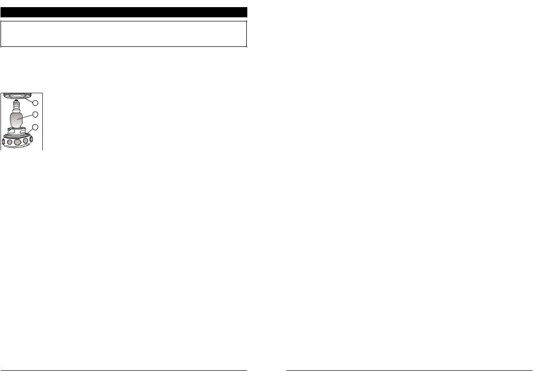
Oven lighting does not function
|
If the oven has been operated and is still hot, wait until it cools |
2 |
down. |
|
|
|
• Bulb is not screwed all the way in - unscrew glass bowl 1 from |
3 |
lamp socket 2, and screw the bulb 3 all the way in (Fig. 23) |
|
|
1 |
• Burnt bulb - unscrew glass bowl 1 of the lamp, and replace |
|
with a new bulb featuring the following parameters: type E14; |
|
230 V; 25 W; temperature resistance 300°C. |
Fig. 23
Too much smoke in the oven
•When grilling, the generated smoke is a normal condition. The amount of smoke can be lowered by decreasing the temperature or reducing the amounts of fat and water in baking dish.
•Dirty turnspit. The fat left on the turnspit from the previous usage will be burnt for some time and thus generating smoke. Take care to clean the turnspit thoroughly after each use.
Burner does not work
•Contaminated nozzle or gas spreader holes. Close the burner taps, clean their parts thoroughly and clear the nozzle with the thin copper wire. Do not use steel wire nor bore the hole.
Spark plug fails to ignite gas (no spark)
•Interruption in electric wiring system. Make sure the cooker is connected to the mains. Check the fuse in the consumer unit - replace if burnt.
•Dirt in space between the burner and its spark plug. Clean thoroughly and dry burners and spark plugs.
Flashing message "0.00" on electronic programmer display
•Voltage drop or momentary interruption in the mains power supply. Disconnect the cooker from the mains, wait a moment, then connect to the mains again, and set the current time.
29
INTRODUCCIÓN
Gracias por el interés que ha manifestado por nuestros productos y por la compra de nuestra cocina.
Antes de instalar y usar la cocina lea y siga atentamente las instrucciones del presente manual que contiene informaciones importantes acerca de la seguridad, así como indicaciones y sugerencias que le facilitarán el uso correcto del aparato.
Con el fin de modernizar el aparato y de mejorar su calidad, el fabricante se reserva el derecho a introducir modificaciones, sin que ello signifique problema alguno para el usuario.
Nuestros aparatos cumplen con las normas de seguridad EN 30-1-1; EN 30-2-1; EN 60335-1; EN 60335-2-6.
La instalación de la cocina la debe realizar un instalador cualificado de aparatos de gas o técnico del taller autorizado que se deberá atener a las normas de instalación vigentes.
El fabricante declina cualquier responsabilidad por daños a enseres o personas derivados de una mala instalación o un uso incorrecto del aparato.
ADVERTENCIA
1.El aparato está adaptado al tipo de gas y presión indicados en la placa de características.
2.En caso de avería del aparato, y particularmente en caso de fuga de gas o de cortocircuito, desconecte el aparato y avise al servicio técnico autorizado.
3.La cocina debe ser reparada exclusivamente por el personal de servicio técnico autorizado. La reparación inadecuada puede causar riesgos graves. La cocina dañada no puede ser usada hasta que no se efectúe la reparación.
4.No levante nunca la cocina agarrando del tirador de la puerta del horno.
5.Durante el uso el aparato se pone caliente. Se aconseja mantener cuidado y no tocar elementos calientes dentro del horno.
6.Si se usa el grill, las partes accesibles pueden calentarse. Evitar el contacto de los ninos.
7.Para evitar el riesgo de choque eléctrico, antes de cambiar la lámpara hay que asegurarse de que el aparato está apagado.
1
|
|
|
|
INDICE |
|
||
|
|
|
|
|
|
|
|
1 |
INFORMACIONES GENERALES .......................................................................... |
3 |
|||||
|
|
1.1 |
CARACTERÍSTICAS |
TÉCNICAS .............................................................................. |
3 |
||
|
|
1.2 |
CONSTRUCCIÓN .................................................................................................... |
|
4 |
||
|
|
1.3 |
PREPARACIÓN ........................................................................................................ |
|
|
4 |
|
|
|
1.4 |
INDICACIONES |
IMPORTANTES ............................................................................. |
4 |
||
|
|
1.5 |
UBICACIÓN DE COCINA ......................................................................................... |
5 |
|||
2 |
INSTALACIÓN ....................................................................................................... |
|
|
6 |
|||
|
|
2.1 |
CONEXIÓN DE COCINA A LA INSTALACIÓN DE GAS ............................................. |
6 |
|||
|
|
|
2.1.1 |
CONEXIÓN A GAS NATURAL ................................................................................ |
6 |
||
|
|
|
2.1.2 CONEXIÓN A LA BOMBONA DE BUTANO ............................................................... |
7 |
|||
|
|
|
2.1.3 |
CAMBIO DE INYECTORES ............................................................................... |
7 |
||
|
|
|
2.1.4 |
REGULACIÓN DEL MÍNIMO .............................................................................. |
8 |
||
|
|
2.2 |
CONEXIÓN DE |
COCINA A LA INSTALACIÓN ELÉCTRICA .................................... |
8 |
||
3 |
ENCIMERA ........................................................................................................... |
|
|
|
9 |
||
|
|
3.1 |
QUEMADORES |
DE |
GAS ........................................................................................ |
9 |
|
|
|
|
3.1.1 ELECCIÓN DE LA LLAMA ADECUADA .................................................................. |
9 |
|||
|
|
|
3.1.2 ENCENDIDO Y APAGADO DE LOS QUEMADORES ............................................... |
10 |
|||
|
|
|
3.1.3 ELECCIÓN DE LOS RECIPIENTES ADECUADOS .................................................. |
10 |
|||
|
|
3.2 |
PLACA ELÉCTRICA ............................................................................................... |
|
10 |
||
|
|
3.3 |
ELECCIÓN DE |
LOS |
RECIPIENTES ADECUADOS ................................................. |
11 |
|
4 |
HORNO ................................................................................................................ |
|
|
|
12 |
||
|
|
4.1 |
CONSTRUCCIÓN Y |
EQUIPAMIENTO .................................................................... |
12 |
||
|
|
4.2 |
MANDO |
SELECTOR |
DE FUNCIONES .................................................................... |
13 |
|
|
|
4.3 |
MANDO |
REGULADOR DE TEMPERATURA ........................................................... |
14 |
||
|
|
4.4 |
PROGRAMADOR ELECTRÓNICO................................................................................. |
14 |
|||
|
|
4.5 |
MANDO |
DEL HORNO............................................................................................ |
14 |
||
|
|
4.6 |
MODALIDADES DE USO ........................................................................................ |
14 |
|||
|
|
4.7 |
INDICACIONES REFERIDAS AL ASADO ................................................................. |
17 |
|||
5 |
PROGRAMADOR ELECTRÓNICO ............................................................................ |
20 |
|||||
|
|
5.1 |
NOTAS |
GENERALES ........................................................................................ |
20 |
||
|
|
5.2 |
SELECCIÓN DEL TIEMPO ACTUAL.............................................................................. |
21 |
|||
|
|
5.3 |
APAGADO DE LA SENAL SONORA.............................................................................. |
21 |
|||
|
|
5.4 |
M I N U T E R O . . . . |
. . . . . |
. . . . . . . . . . . . . . . . . . . . . . . . . . . . . . . . . . . . . . . . . . . . . . . . . . . . . . . . . . . . . . . . . . . . . |
2 2 |
|
|
|
5.5 |
PROGRANACIÓN DEL TIEMPO DE TRABAJO DEL HORNO................................................ |
22 |
|||
|
|
5.6 |
PROGRANACIÓN DE LA HORA DE APAGADO................................................ |
23 |
|||
|
|
5.7 |
MANDO AUTOMÁTICO ............................................................................................. |
23 |
|||
|
|
5.8 |
MODIFICACIÓN DE VALORES SELECCIONADOS............................................................. |
24 |
|||
|
|
5.9 |
ANULACIÓN DE VALORES SELECCIONADOS................................................................ |
24 |
|||
|
|
5.10 |
MANDO |
MANUAL............................................................................................. |
25 |
||
|
|
5.11 |
FUNCIÓN DEL BLOQUEO......................................................................................... |
25 |
|||
|
|
5.12 |
MODO |
NOCTURNO............................................................................................. |
25 |
||
6 |
LIMPIEZA Y MANTENIMIENTO ............................................................................ |
26 |
|||||
|
|
6.1 |
ADVERTENCIAS |
GENERALES .............................................................................. |
26 |
||
|
|
6.2 |
LIMPIEZA DE LA TAPA ........................................................................................... |
26 |
|||
|
|
6.3 |
LIMPIEZA DE LOS QUEMADORES DE GAS .......................................................... |
26 |
|||
|
|
6.4 |
LIMPIEZA DE LA PLACA ELÉCTRICA .................................................................... |
27 |
|||
|
|
6.5 |
LIMPIEZA DEL HORNO .......................................................................................... |
27 |
|||
|
|
|
6.5.1 |
DESMONTAJE DE LA PUERTA DEL HORNO ......................................................... |
28 |
||
6.5.2DESMONTAJE DE LAS GUÍAS Y DE LAS PROTECCIONES
|
LATERALES CATALÍTICAS .............................................................................. |
28 |
6.5.3 |
DESMONTAJE DE LA PROTECCIÓN CATALÍTICA TRASERA................................ |
29 |
6.5.4 |
LIMPIEZA DE LA CAVIDAD DEL HORNO ................................................................ |
29 |
7 ELIMINACIÓN DE DEFECTOS ............................................................................. |
30 |
|
2
CLEANING AND MAINTENANCE |
|
|
|
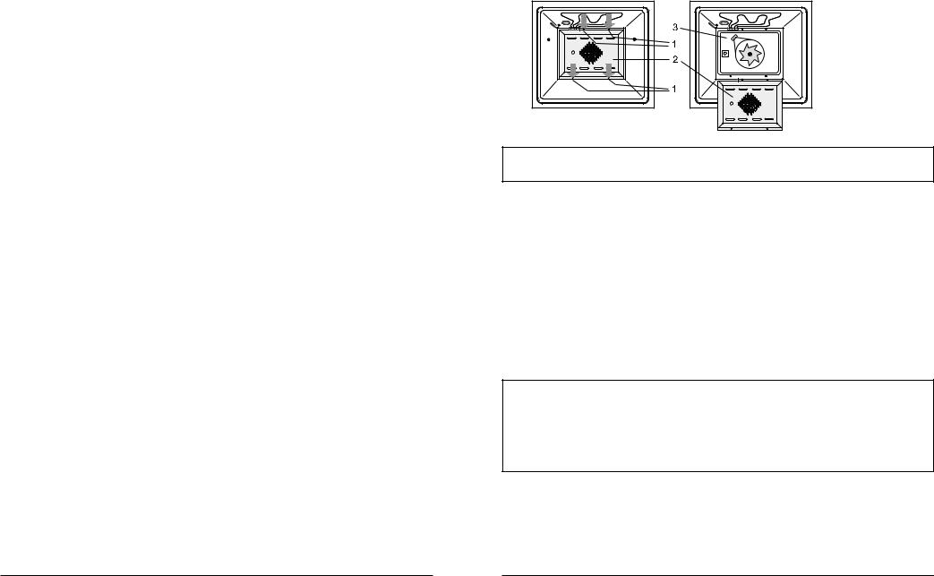
6.5.3 DISMANTLING THE CATALYTIC REAR COVER
-unscrew four screw 1 (marked with arrows in fig. 22),
-remove cover 2 from rear wall 3 of the oven.
Fig. 22
CAUTION !
The oven must be switched off before removing the guard.
6.5.4 CLEANING OF THE CHAMBER INTERIOR
•After removing all catalytic shields you can clean the inside of the chamber.
•Clean the enamelled surfaces with agents intended for cleaning the kitchen.
•In order to clean stubborn baked stains you can use a special cleanser intended for oven cleaning. As these detergents are caustic, you should use them in minimal amount and with a great caution, observing the recommendations of detergent manufacturer.
•In order to make cleaning of the oven interior easier, you can switch on the lamp. In order to do it, set the function selection knob to any function and the temperature control knob in "0" position. The lamp will remain lit.
•In order to clean glass cover of the lamp (item 1 in fig. 23), unscrew it, wash in warm water and detergent, dry and refit.
NOTE!
1.Use the special oven cleaning agent only for enamelled surfaces. You must not use it for cleaning of catalytically enamelled shields.
2.While refitting the guides, make sure that they are properly fixed. The bar limiting sliding of the insert into the oven should be placed in the rear part of the oven.
28

|
CLEANING AND MAINTENANCE |
|
|
6.5.1 DISASSEMBLY OF OVEN DOOR
•Open the door entirely
•Lock hinges on both sides of the door by placing the clamping ring 1 on the catch 2 of the hinge bow 3 (fig. 20)
•Next grasp the door with both hands, turn it in closing direction through an angle of 450 and take out the hinges.
Fig. 20
Taking out the oven door
CAUTION!
1.The hinge bow is tense with a big strength, therefore while taking out the door a special care must be taken not to cut one's own fingers.
2.During cleaning the upper wall of oven you should pay attention to electric heaters, temperature sensor and lamp of oven illumination; do not change position of sensor setting.
3.Do not pour water onto the bottom of oven otherwise it may trickle through some possible leakage and get on the lower heater.
When the oven door is removed, you can dismantle both pairs of quides. The quides and oven bottom should be preferably cleaned each time they get dirty.
6.5.2 DISASSEMBLY OF GUIDES AND SIDE CATALYTIC SHIELDS
a) |
b) |
Fig. 21
In order to replace the side catalytic shields, first disassemble both sets of the guides.
Disassembling the guides:
−slightly press the upper bar of the ladder 1 down and release is from the blocking nut 2, (fig. 21a),
−turn the guides 4 towards inside of the oven and remove them from the holes (fig. 21b),
−remove catalytic shields 3.
Clean the ladder guides with a sponge or brush using dish washing agent. After cleaning, take all actions in the reverse sequence to disassembly.
INFORMACIONES GENERALES |
|
|
|
1 INFORMACIONES GENERALES
1.1 CARACTERÍSTICAS TÉCNICAS
La cocina se ha diseñado para la preparación de alimentos exclusivamente en el hogar.
Su uso para otros fines está prohibido.
Tabla 1
|
|
|
|
MODELO |
|
|
|
|
|
|
|
|
|
|
|
4CF-631 LMD NAT |
|
|
|
|
|
4CF-631 LMD BUT |
|
|
|
|
|
|
|
Dimensiones externas (altura x anchura x profundidad) |
[mm] |
850 x 600 x 600 |
|
||
|
|
|
|
|
|
Dimensiones |
altura |
|
[mm] |
330 |
|
|
|
|
|
|
|
útiles del |
anchura |
|
[mm] |
428 |
|
horno |
|
|
|
|
|
profundidad |
|
[mm] |
415 |
|
|
|
|
|
|||
|
|
|
|
|
|
Potencia nominal de la cocina eléctrica |
|
[kW] |
4,2 |
|
|
|
|
|
|
|
|
|
quemador pequeño |
|
1,1 kW |
1 unid. |
|
|
|
|
|
|
|
Encimera |
quemador mediano |
|
2,0 kW |
1 unid. |
|
|
|
|
|
|
|
quemador grande |
|
3,1 kW |
1 unid. |
|
|
|
|
|
|||
|
|
|
|
|
|
|
placa eléctrica |
ø180 mm / 2000 W Ex |
1 unid. |
|
|
|
|
|
|
|
|
Encendedores de los quemadores de gas |
|
|
• |
|
|
|
|
|
|
|
|
Regulador de la temperatura del horno |
|
|
• |
|
|
|
|
|
|
|
|
Programador electrónico |
|
|
• |
|
|
|
|
|
|
|
|
|
resistencia superior |
|
[kW] |
0,7 |
|
|
|
|
|
|
|
|
resistencia inferior |
|
[kW] |
1,5 |
|
|
|
|
|
|
|
|
resistencia del grill |
|
[kW] |
2,0 |
|
Horno |
|
|
|
|
|
girapollos |
|
|
• |
|
|
eléctrico |
|
|
|
||
|
|
|
|
|
|
|
resistencia circular |
|
[ kW] |
2,0 |
|
|
|
|
|
|
|
|
ventilador |
|
|
• |
|
|
|
|
|
|
|
|
iluminación del horno |
|
15/25 W |
• |
|
|
|
|
|
|
|
|
paneles autolimpiantes adicionales |
|
• |
|
|
|
|
|
|
|
|
|
bandeja esmaltada |
|
|
1 unid. |
|
|
|
|
|
|
|
Equipamiento |
rejilla |
|
|
1 unid. |
|
|
|
|
|
|
|
del horno |
|
|
|
|
|
protección de los mandos |
|
|
1 unid. |
|
|
|
|
|
|
||
|
|
|
|
|
|
|
soporte del girapollos |
|
|
1 unid. |
|
|
|
|
|
|
|
Categoría: II2H3+ - ES, PT Categoría: II2E+3+ - FR
G 20 20 mbar; G 25 20 mbar; G 25 25 mbar; G 30 30 mbar; G 30 50mbar
27 |
3 |
|
INFORMACIONES GENERALES |
|||
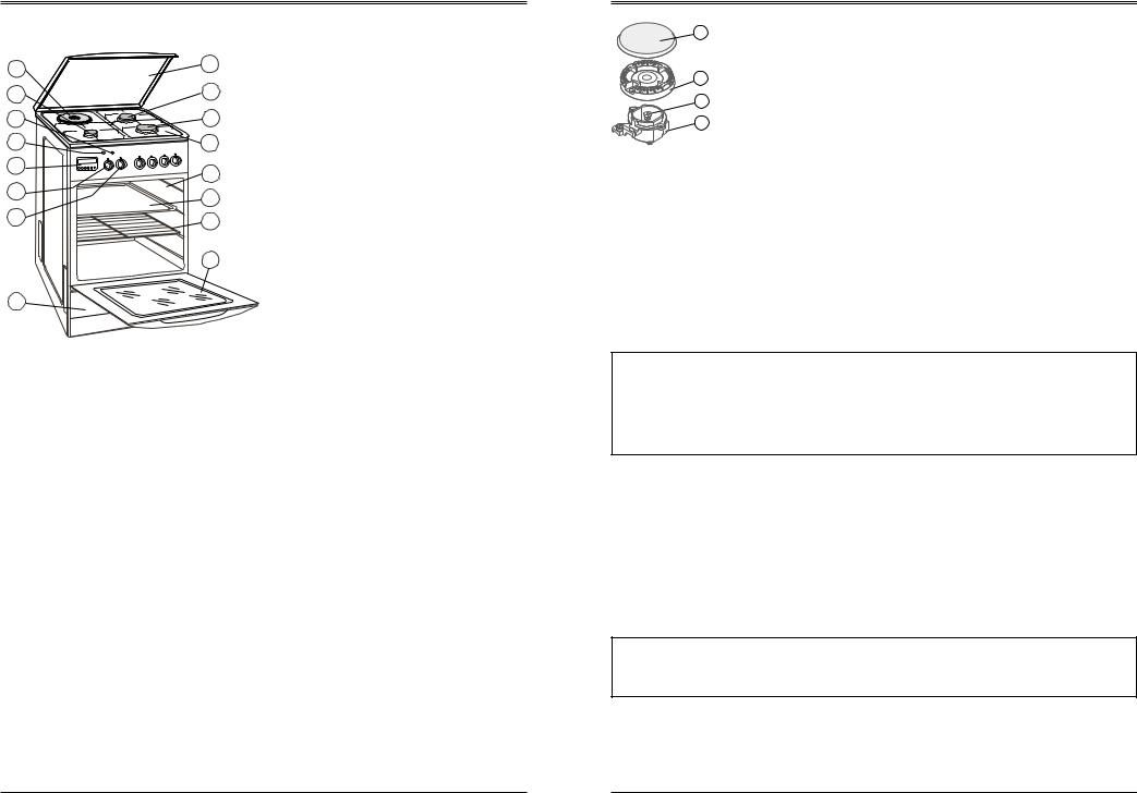
1.2 CONSTRUCCIÓN |
|
|
|
|
9 |
5 |
Fig. 1 |
||
|
|
|
||
6 |
7 |
1 |
- encimera |
|
2 |
- horno eléctrico |
|||
|
|
|||
16 |
8 |
3 |
- puerta del horno |
|
15 |
1 |
4 |
- cajón |
|
5 |
- tapa |
|||
|
|
|||
12 |
2 |
6 |
- quemador pequeño |
|
|
7 |
- quemador mediano |
||
|
|
|||
11 |
13 |
8 |
- quemador grande |
|
|
||||
10 |
14 |
9 - placa ø180mm / 2000W Ex |
|
10 - mando selector funciones horno |
|||
|
|||
|
|
||
|
|
11 - mando regulador de temperatura |
312 - programador electrónico
13 - bandeja
14 - rejilla
4 15 - piloto regulador de temperatura
16 - piloto funcionamiento de cocina
1.3 PREPARACIÓN
1.Retire de la cocina los elementos de embalaje, incluido el plástico que recubre las partes de acero inoxidable. Los materiales de embalaje tienen que ser tratados de acuerdo con la normativa vigente.
2.Limpie las superficies esmaltadas y de cristal con un paño suave y húmedo.
3.Antes de usar la cocina por primera vez, ponga la placa eléctrica en ”6” durante unos 5 minutos sin recipiente. Durante este tiempo se quemará la superficie de protección que recubre la placa. Cuando se enfríe, limpie la placa con un paño seco.
4.El horno, la rejilla, la bandeja, etc. límpielos con una disolución caliente de detergente.
5.Ponga el horno en marcha a temperatura máxima durante 1 hora. El humo y olor que se desprenden del horno durante este tiempo son de poca importancia y basta asegurar la ventilación correcta abriendo las ventanas.
1.4 INDICACIONES IMPORTANTES
La instalación de la cocina la debe realizar un instalador autorizado o técnico del centro de servicio autorizado. En caso de avería desconecte la cocina de la red eléctrica.
1.Durante el uso, los quemadores, las placas eléctricas y la cavidad del horno se calientan. ¡Evite el acceso de los niños!
2.Las grasas y los aceites sobrecalentados pueden quemarse fácilmente, por lo tanto los alimentos de este tipo prepárelos siempre bajo control.
3.Para quitar las cazuelas de la encimera y sacar moldes del horno utilice guantes de protección.
4
CLEANING AND MAINTENANCE
• The burner frame area around the nozzle should always be clean.
1 |
The nozzle may get clogged due to the dirt built up close to the |
|
|
||
|
nozzle, and as a consequence the burners can produce poor flame |
|
2 |
or stop burning at all. To clean the nozzles, wipe them with a brush |
|
moistened in solvent. |
||
|
||
4 |
• Dry the clean burners thoroughly since, when moistened, they can |
|
|
3prevent the gas from igniting, or cause improper combustion.
Fig. 19 1 - burner cap; 2 - flame spreader; 3 - frame; 4 - nozzle
6.4 CLEANING THE HOT PLATE
•Clean the hot plate with a damp sponge, and then dry it by turning it on for a few seconds. To ensure the aesthetic appearance, apply any commercially available grease intended for the maintenance of hot plates.
•The hot plate rings can be cleaned with agents intended for the maintenance of stainless steel parts. As a result of overheating, the ring can get yellow tint, which is normal.
•If the hotplate is to be out of use for a long time, apply some grease periodically.
6.5 OVEN CLEANING
CAUTION!
1.Before cleaning you should wait until oven cools down. Hot heaters may cause burns.
2.Cleaning the oven in use of appliances for steam generation under pressure is not allowed.
3.It is the best to clean the bottom of the oven after each use, not to allow the remains of food and spots of oil to roast again.
•The oven compartment is coated with ceramic enamel, and both of the side covers and the rear cover are coated with catalytic enamel.
•During normal use, the oven compartment is heated to high temperatures, which facilitates absorbing the emitted fumes by the catalytic enamel.
•Periodically, especially after cooking very fat dishes, the self-cleaning cycle must be carried out. It is done by in turning the oven on for one hour's time and setting the maximum temperature (250°C). During this time, the oven door should be closed. During the self-cleaning cycle, the dirt deposited on the oven walls oxidizes and evaporates.
CAUTION !
No detergents nor soap can be used for cleaning the covers coated with the catalytic enamel as this could cause damage to the enamel.
•After some time, the catalytic covers will loose their self-cleaning properties; when their surface becomes glossy they should be replaced.
•In order to replace the catalytic covers, it is necessary to remove the oven door and guide assembly.
26
|
CLEANING AND MAINTENANCE |
|
|
6 CLEANING AND MAINTENANCE
Warning !
Before proceeding with washing and cleaning, disconnect the cooker from the electric power supply and wait until it cools down.
6.1 GENERAL REMARKS
•The cooker must be regularly cleaned. While cleaning, avoid using any coarse-grained, abrasive powders, wire sponges aggressive chemicals and sharp objects.
•The parts made of stainless steel, knobs and fascia panel should be cleaned with soft cleaning liquids without any abrasive agents.
•Clean the enamelled parts with a soft cloth or sponge moistened in lukewarm water with addition of soft detergent, avoiding too much water. Remove heavy stains with special agents used for cleaning the kitchen.
•While cleaning the hob, take care that no water enter the burner housing holes. Surfaces around the burners should always be clean as contamination obstructs the proper combustion of the gas mixture.
•The burners and spark plugs should be kept clean and dry to ensure their proper operation.
•After using them, baking tins and forms, and meat roasting pans should be soaked in lukewarm water with the addition of washing liquid, then washed and carefully dried.
•Check to make sure that the oven door seal is clean.
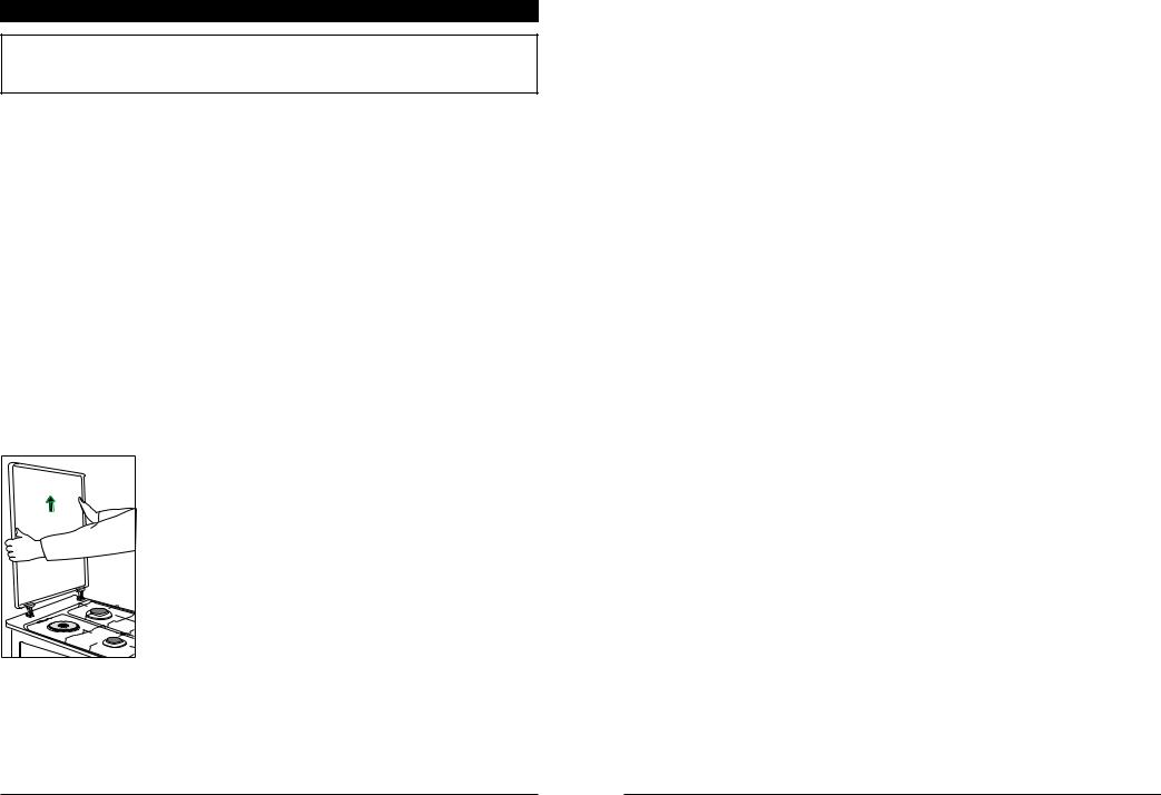
6.2 CLEANING THE LID
• When cleaning the cooker, it is possible to remove the |
cover. |
• In order to do so, turn the lid to its vertical position, take |
hold of its side with both hands, move the cover upwards |
pulling it out of the hob holes (Fig. 18). |
• Then wash the cover, dry it and put aside. |
Fig. 18 |
6.3 CLEANING THE BURNERS
•Remove the external parts of the burners, and soak them in lukewarm water with detergent, and then clean each part separately. The burner caps can be cleaned with a sponge, and the gas spreader with a soft wire brush. After the cleaning, make sure that the flame holes are clear.
25
INFORMACIONES GENERALES |
|
|
|
4.Antes de cerrar la tapa apague todos los quemadores y la placa eléctrica. La tapa de cristal puede romperse si se calienta en exceso.
5.Durante su uso la cocina se calienta. ¡Tengan cuidado de no tocar elementos calientes dentro del horno!
6.En el horno y en el cajón no almacene objetos inflamables y no resistentes al calor.
7.No sobrecargue la puerta abierta. No se apoye sobre ella.
8.Los cables de alimentación de otros electrodomésticos deben pasar lejos de la cocina encendida y caliente.
9.No utilice el aparato para calentar el local.
10.En caso de fuga de gas:
-cierre la llave en la instalación de gas o en la bombona de butano,
-apague todos los quemadores y otras llamas vivas,
-ventile el local, abra las ventanas,
-no ponga en marcha aparatos eléctricos (tampoco la iluminación),
-avise de la avería al servicio de asistencia autorizado.
Quemadores
-No ponga cazuelas deformadas o inestables sobre la parrilla ya que pueden volcar y apagar la llama.
-No quite la parrilla y ponga cazuelas directamente sobre el quemador.
-No ponga cazuelas vacías sobre el quemador encendido.
-Mantenga los quemadores limpios, evite su ensuciamiento durante la ebullición.
-Antes de quitar la cazuela, reduzca o apague el fuego.
Placa eléctrica
-Mantenga la placa limpia. La placa sucia no transmite la totalidad de su potencia.
-Ponga en marcha la placa sólo después de colocar la cazuela encima, salvo la primera puesta en marcha.
-No ponga cazuelas mojadas ya que la humedad provoca la corrosión.
-No moje la placa caliente con agua fría.
-Apague la placa unos minutos antes de terminar la cocción ya que la placa acumula el calor y sigue estando caliente algún tiempo después de apagarse.
-No prepare en la placa los alimentos en lámina de aluminio o en vajilla de plástico; no ponga encima platos de plástico, etc.
1.5UBICACIÓN DE COCINA
•El aparato puede instalarse y usarse exclusivamente en locales ventilados de forma adecuada, según las normas de instalación en vigor de cada país. Las rejillas de ventilación deben permanecer abiertas o es preciso instalar un sistema de ventilación forzada (campana).
•El local debe ser seco. La ubicación del aparato debe garantizar el acceso libre a todos los elementos de mando.
5
|
INSTALACIÓN |
|
|
|
|
•Sobre el aparato debe mantenerse un espacio libre para la adecuada evacuación de vapores. En caso de instalar una campana, la distancia mínima entre la encimera de gas y la campana debe ser de 650 mm.
•La cocina puede ser colocada en fila de los muebles solamente hasta la altura de 850mm. La distancia entre los lados laterales de la cocina y los armarios de la cocina debe ser por lo menos 30mm.
•El aparato debe instalarse lejos de materiales inflamables. No coloque muebles por encima de la cocina.
•Antes de usar el aparato, es preciso nivelarlo. Para este fin dispone de patas regulables a las que se accede retirando el cajón.
2 INSTALACIÓN
Antes de conectar la cocina, asegúrese de que la instalación esté preparada para funcionar con el gas que se le vaya a suministrar (tipo y presión). En caso contrario, realice el cambio de inyectores y regule los mínimos.
La cocina puede conectarse a la red interna de casa o a la bombona de butano. El gas debe conectarse al manguito con ayuda de accesorios adecuados.
Antes de proceder a instalar la llave de gas debe estar cerrada.
2.1 CONEXIÓN DE LA COCINA A LA INSTALACIÓN DE GAS
La cocina puede conectarse a la instalación interna de gas o a la bombona de butano. La instalación de gas debe disponer de una llave de cierre por si es necesario cortar el flujo de gas.
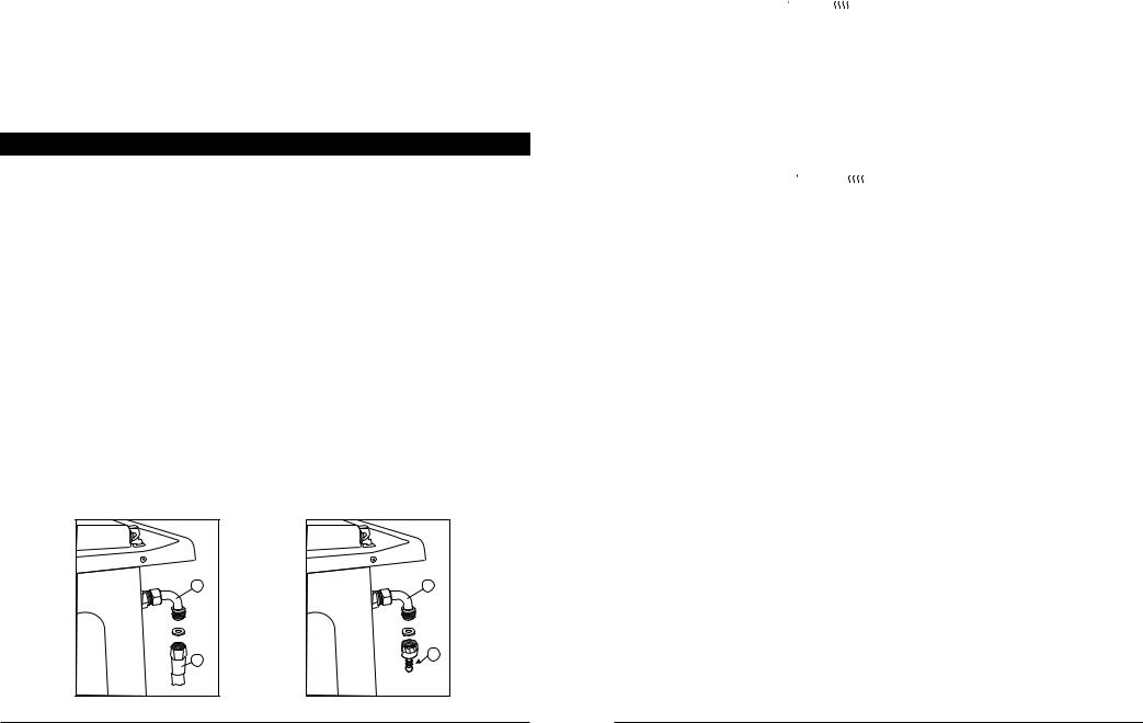
La cocina está equipada con un codo de entrada (1) para la conexión de gas por medio de los accesorios adecuados.
Antes de iniciar la conexión, hay que cortar el gas y sacar la clavija del enchufe.
2.1.1 CONEXIÓN A GAS NATURAL
1
Fig. 2
2
1
Fig. 3
3
ELECTRONIC PROGRAMMER |
|
|
|
Before any protecting actions are started, the programmer should be in the manual mode.
Locking the oven:
–simultaneously press  and
and  buttons and hold them in this position for approx. 8 seconds, till the word " " appears on the display,
–press "+" button,
–the word " " appears on the display and the lock symbol  is illuminated,
–after approx. 5s the current time appears on the display near the lock symbol  ; the oven is locked.
Unlocking:
–the programmer should be in the manual mode,
–simultaneously press  and
and  buttons and hold them in this position for approx. 8 seconds, till the word " " appears on the display,
–press "+" button,
–the word " " appears on the display and the lock symbol  is off,
–after approx. 5s the current time will appear again on the display; the oven in unlocked.
5.12 NIGHT BLACKOUT
At the time between 22.00 and 5.59 the programmer automatically reduces intensity of the display lighting.
During this time, the display is illuminated intensively only when:
–the timer is measuring out the time,
–currently a program is executed,
–any button has been pressed.
6 |
24 |
|
ELECTRONIC PROGRAMMER |
|
|
COMMENT !
STOP
1.Pressing button during operation of the oven will enable you to display the programmed time of switching off.
2.When  button is depressed, the programmed time of the oven operation is displayed. If the oven has already started to run, the time which is left to complete the program will appear.
5.8 CHANGING SETTINGS
Settings can be changed within the period up to 5s from commencement of programming or after deletion of the program.
Changing the time of operation:
–press  button,
–using "+" and "-" buttons you can set a new time.
Changing the time of switching off:
STOP
–press button,
–using "+" and "-" buttons you can set a new time.
5.9DELETING SETTINGS
Deleting the time of operation:
–press  button,
–press "-" button and hold it till the message "0.00" appears on the display.
Changing the time of switching off:
STOP
–press button,
–press "-" button and hold it till the message "0.00" appears on the display.
When the program is deleted, operation of the oven can be reprogrammed.
5.10 MANUAL CONTROL
1.If during execution of the program the user intends to start manual operation, the program should be deleted and  button should be pressed.
2.Pressing of this button will disable functions of the programmer. Then the oven is operated only using the oven functional knob and temperature regulator knob.
3.In the manual control mode you can use the timer.
NOTE !
Pressing  button will result in switching over to the manual operation mode. It means that heaters of the oven are switched on for undetermined time; in order to switch them off, set the functional knob of the oven to "0" position.
5.11 LOCKING FUNCTION
This function enables protection from tampering of children. It means that when this function is chosen, the child may select any program on the programmer but the program will not be changed.
23
INSTALACIÓN |
|
|
|
Al codo (1) enroscar el conducto rígido o flexible con cubierta de metal (2), de acuerdo con el reglamento nacional vigente. El modo de conexión se presenta en la fig. 2.
2.1.2 CONEXIÓN A LA BOMBONA DE BUTANO
La conexión de la cocina a la bombona se realizará mediante el accesorio que se suministra (3) a un tubo de goma que lleve la marca en conformidad con las normas en vigor. El tubo debe asegurarse en los dos extremos mediante abrazaderas de manguera. El modo de conexión se representa en la figura 3.
Después de la conexión a la bombona, controle la estanqueidad del grifo de la bombona, la conexión del reductor con la bombona y su funcionamiento.
¡ATENCIÓN!
1.Es inadmisible comprobar la estanqueidad por medio de llama viva (p.ej. cerilla o vela). ¡Corre el riesgo de explosión!
2.Temporalmente, compruebe el estado del tubo y la estanqueidad de sus conexiones conforme a las normas vigentes del país.
2.1.3 CAMBIO DE INYECTORES
En caso de que la cocina no estuviera preparada para funcionar con el tipo de gas disponible, se deberán cambiar los inyectores y regular los mínimos.
¡ATENCIÓN!
Antes de cambiar los inyectores y regular los mínimos desconecte la cocina de la red eléctrica. Durante la regulación de los mínimos no suelte por completo el tornillo regulador.
Cambio de inyectores:
-cerrar la llave de la instalación o de la bombona,
-cerrar todos los grifos de la cocina,
-quitar las parrillas, las tapaderas y las coronas de quemadores,
-desenroscar los inyectores anteriores y sustituirlos por nuevos,
-colocar las tapaderas y las coronas de quemadores,
-realizar la regulación de los mínimos y comprobar la estanqueidad de las conexiones.
Los diámetros de inyectores para cada quemador se indican en la tabla 2.
|
|
|
|
Tabla 2 |
|
|
|
|
|
|
|
Tipo de gas |
Quemador |
Quemador |
Quemador |
||
pequeño |
medio |
grande |
|||
|
|
||||
|
|
|
|
|
|
G20 |
20 mbar |
0,75 |
1,02 |
1,25 |
|
|
|
|
|
|
|
G25 |
20 mbar |
0,80 |
1,12 |
1,35 |
|
|
|
|
|
|
|
G25 |
25 mbar |
0,75 |
1,02 |
1,26 |
|
|
|
|
|
|
|
G30 |
30 mbar |
0,50 |
0,70 |
0,80 |
|
|
|
|
|
|
|
G30 |
50 mbar |
0,50 |
0,60 |
0,75 |
|
|
|
|
|
|
|
7
|
INSTALACIÓN |
|
|
|
|
|
2.2.4 REGULACIÓN DEL MÍNIMO |
|
La regulación de los mínimos de los grifos consiste en regular la llama mínima del
quemador.
Para este fin hay que:
-encender el quemador con la llama al mínimo y quitar el mando simplemente tirando de él sin girar,
|
|
- girar con el tornillo regulador A (figura 4) hasta poner al |
|
|
mínimo la llama que en esta posición no deberá |
|
|
apagarse al girar rápidamente con el grifo del máximo al |
A |
Fig. 4 |
mínimo y al revés, |
-la regulación se considera exitosa cuando el núcleo de la llama tiene forma de cono de color verde-azul de 2 - 4 mm de altura,
-si en la instalación de gas se producen cambios de presión visibles, es preciso regular los mínimos con baja presión para que el quemador no se apague durante su funcionamiento normal,
-después de realizar la regulación, poner el mando y apagar la llama cerrando el grifo.
2.2 CONEXIÓN DE COCINA A LA INSTALACIÓN ELÉCTRICA
•Las cocinas equipadas con un cable de alimentación con clavija deben conectarse al enchufe con contacto de protección.
•La conexión al enchufe sin contacto protector puede causar choques eléctricos en caso de daños de la instalación eléctrica de la cocina.
•El enchufe de la red debe ser accesible para el usuario. Evite el contacto del cable de alimentación con elementos calientes del aparato.
Si el aparato no está equipado con el cable de alimentación con clavija, deberá ser instalado adecuadamente por un instalador cualificado conforme a las normas vigentes de seguridad. Se prohibe realizar cambios o remodelaciones de la instalación de gas y eléctrica del aparato.
Antes de proceder a la conexión asegúrese de que:
-la tensión nominal en el local es igual que la indicada en la placa de características,
-la línea de alimentación del aparato está preparada para suministrar la potencia máxima consumida por el aparato indicada en la placa de características.
A continuación se representa el esquema de posibles conexiones:
Inf. nominal by phases: 18,3 A Protection: 20,0 A
3 x 2,5 mm2
~230V 50Hz
L N
L1 N PE
 230V
230V 

~230V 50Hz
L N
L1 |
|
L2 PE |
||||
|
|
|
230V |
|
|
|
|
|
|
|
|
|
|
Fig. 5
8
ELECTRONIC PROGRAMMER |
|
|
|
Programming the time of switching off: |
|
STOP |
|
–press button,
–using "+" and possibly "-" setting buttons set the time of switching off the oven e.g. 11.50.
When the time set elapses:
–the oven is switched off automatically,
–sound signal is activated,
–"AUTO" pulsates on the programmer display.
If the dish is not baked sufficiently, you may reprogram the time of operation as in the point above, or set the time of switching the oven off, or depress the manual operation
button  and control further operation of the oven.
When the operation is over, move the functional knob of the oven to zero position.
5.7 AUTOMATIC CONTROL
Operation in automatic mode consists in programming the time of operation and time of switching off the oven an in points 5.5 and 5.6.
The oven will be switched on automatically at the time defined, and when the time set elapses it will be switched off automatically.
Example - Roasting beef
–it is 13.00
–roasting time 2 hours
–roasting temperature 2200C
–the dish to be prepared for 17.00
•Put the meat into an oven-pan, add approx. 10 spoonfuls of water and cover it with a lid. Then put the pan into the oven, place it on the mesh on a chosen level, and close door of the oven.
•Using the functional knob choose the position  , and using the thermoregulator knob set the temperature of 2200C.
•Press  button and using "+" and possibly "-" setting buttons determine the roasting time i.e. 2 hours.
• Press |
STOP |
button and using "+" and possibly "-" setting buttons set the time of 17.00 |
(time when roasting is complete).
1.Operation of the oven has be programmed and it will be carried out automatically.
2.At 15.00 the oven will be switched on automatically and it will run for 2 hours. At 17.00 the appliance will be switched off automatically which is signalled by activation of the
STOP
sound signal. At this time "AUTO" pulsates and  is off.
3.If the dish is not roasted sufficiently, you may reprogram operation of the oven, or press the manual operation button  and control further roasting.
22
|
ELECTRONIC PROGRAMMER |
|
|
5.4 TIMER
The timer is designed for sound signalling when the time set elapses. You can use it when performing short time cooking operations (e.g. boiling eggs). The timer does not switch the oven off.
a)when the time is being measured out by the timer, you can program operation of the oven,
b)the timer can be set during execution of any program.
Setting the timer:
–press  button,
–using: "+" and possibly "-" setting buttons set the desired time (e.g. 3 minutes).
After approx. 5 s the current time will appear on the display and  indicator will be illuminated. When the time set (i.e. 3 minutes) elapses, the sound signal will be activated. The signal can be disabled by pressing any button.
Deleting the timer setting:
–press  button,
–press "-" setting button and hold it till the message "0.00" appears on the display.
NOTE !
In order to check how much time is left till the end of the timer operation, press  button. Depressing of this button does not stop measuring of time.
5.5 PROGRAMMING THE OVEN OPERATION TIME
When the time of operation has been programmed and the oven function selected, the oven will be switched on immediately.
Programming the time of operation:
–press  button,
–using "+" and possibly "-" setting buttons set the required time of operation e.g. 35 minutes
When the time set elapses, the following occurs:
–the oven is switched off automatically,
–sound signal is activated,
–the symbol "AUTO" pulsates on the programmer display and the symbol  is off. If further operation of the oven is needed (e.g. in order to finish baking of a cake), you
may reprogram the time, or press the manual operation button  and control further operation of the oven.
When the operation is over, move the functional knob of the oven to zero position.
5.6 PROGRAMMING THE TIME OF SWITCHING OFF
When the time of switching off is programmed and the oven function selected, the oven is switched on immediately.
21
ENCIMERA |
|
|
|
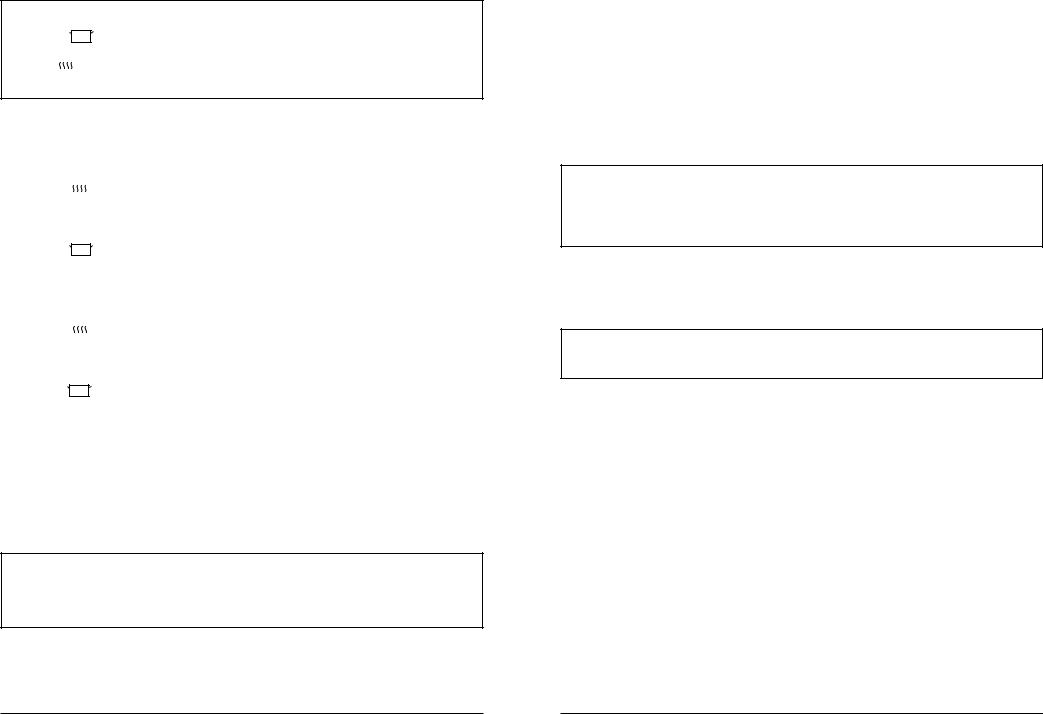
La instalación eléctrica de alimentación de cocina debe estar equipada con un interruptor de seguridad que actúa en caso de avería. La distancia de apertura de los contactos del interruptor debe ser igual o superior a 3 mm.
Para conectar el cable de alimentación a la red se debe tener en cuenta que:
-el cable verde-amarillo (de protección) debe conectarse al borne de tierra  ,
,
-el cable azul es neutro (cero),
-los cables marrón, negro y rojo son para la fase (live),
-el cable no debe entrar en contacto con las superficies cuya temperatura sea superior a 75OC,
-en caso de que el aparato se entregue sin cable, utilizar uno del tipo H05RR- F ó H05V2V2 con la sección adecuada como arriba se ha indicado.
3 ENCIMERA
3.1 QUEMADORES DE GAS
•El flujo de gas en cada quemador se abre y
|
se cierra girando el mando. |
|
• Antes de encender el quemador asegúrese |
|
de que el mando que quiere usar |
|
corresponde al quemador (o placa eléctrica) |
|
que va a utilizar. |
|
• Las correspondencias de mandos con |
|
quemadores y placa se han indicado en las |
Fig. 6 |
figura 6. |
El funcionamiento correcto de quemadores y el ahorro de energía se consigue a través de la regulación adecuada de la llama y elección correcta de los recipientes.
3.1.1 ELECCIÓN DE LA LLAMA ADECUADA
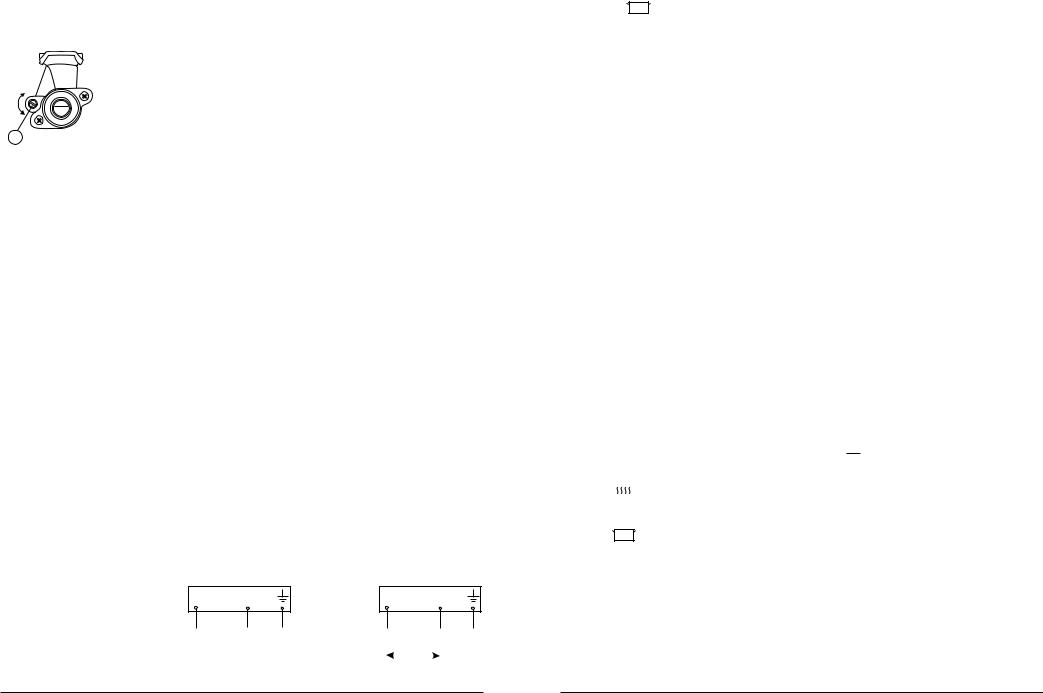
•La llama no debería sobrepasar el fondo del recipiente y debería abarcar unos 2/3 de su superficie. Este modo de uso permite consumir menos gas y evita el ensuciamiento del recipiente por la llama.
•La fuerza de la llama depende de la posición del mando (ver figura 8). La llama máxima debe usarse hasta alcanzar la ebullición y para etapas siguientes de cocción es aconsejable usar la llama mínima. La llama debe regularse dentro del rango de las posiciones  y
y  .
.
Posiciones del mando:
0 |
0 |
- quemador apagado |
|
||
|
0 |
- llama completa |
|
0 |
- llama mínima |
Fig. 7
9
|
ENCIMERA |
|
|
|
|
3.1.2 ENCENDIDO Y APAGADO DE LOS QUEMADORES
Encendido de los quemadores
-Apretar el mando del quemador seleccionado, girarlo en sentido antihorario y mantener apretado hasta que el gas se encienda,
-soltar el mando y posicionarlo en el valor deseado.
Apagado de los quemadores
Los quemadores se apagan girando el mando del grifo de gas en sentido horario hasta la posición cero “0”.
Alimentación de gas de la bombona
Antes de encender el primer quemador abrir la llave en la bombona de butano y luego seguir las instrucciones del punto anterior.
Al cerrar, antes de apagar el último quemador hay que:
-cerrar la llave de la bombona,
-después de apagar la llama, cerrar el mando del quemador.
Al no usar la cocina, la llave de la bombona debe permanecer cerrada.
3.1.3 ELECCIÓN DE LOS RECIPIENTES ADECUADOS
Recipiente demasiado pequeño respecto |
Recipiente bien ajustado |
al tamaño del quemador y falta de tapa |
|
Fig. 8 |
|
•Durante la cocción los recipientes deben cubrirse con las tapas lo que permite evitar concentraciones de vapor en el local.
•Los diámetros mínimos de recipientes para cada quemador:
- para el quemador pequeño |
ø 90 mm, |
|
- |
para el quemador mediano |
ø 120 mm, |
- |
para el quemador grande |
ø 140 mm, |
3.2 PLACA ELÉCTRICA
¡ADVERTENCIA!
Al aparecer cualquier grieta en la placa eléctrica, desconecte el aparato inmediatamente y avise al personal autorizado para realizar reparaciones.
10
ELECTRONIC PROGRAMMER |
|
|
|
 - Oven operation signal
Continuous lighting signals operation of the oven (providing that it is switched on).
 - Timer signal
Continuous lighting means that the timer is set.
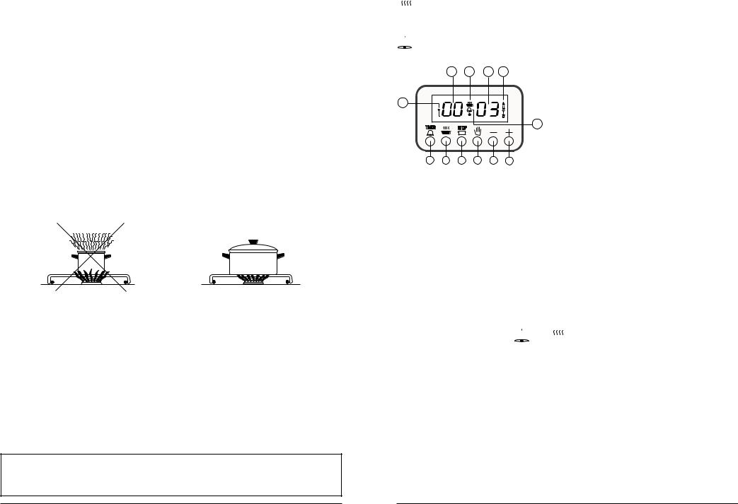
B C D A
F |
|
A - Automatic operation; |
|
B - Hours; |
|
|
|
|
|
E |
C - Oven operation symbol; |
|
D - Minutes; |
|
|
|
|
|
|
E - Timer symbol; |
|
|
F - Lock symbol; |
1 2 3 4 5 6
Fig. 17 Electronic programmer
1 - timer button; 2 - operating time button; 3 - operation end button; 4 - manual operation button; 5 - time "decreasing" setting button; 6 - time "increasing" setting button1.
1.When the cooker has been connected to the power supply mains, pulsating messages "0.00" and "AUTO" appear on the programmer display.
2.The first action which should be taken upon connection of the cooker to power supply is setting the current time.
3.The current time should be set also after decay of voltage in the mains lasting longer than 5s.
4.Accuracy of the programmer readings depends on parameters of the supply mains, therefore it should be adjusted periodically by comparing it with another timer.
5.2SETTING THE CURRENT TIME
–simultaneously depress  and
and  buttons,
–using "+" (and possibly "-") setting button set the required time e.g. 11.38,
–when the time has been set, release all buttons.
During the time of approx. 5s from releasing of the buttons, the time will be stored. The time set i.e. 11.38 will appear on the display. When the current time is set, the oven will run in the manual mode.
5.3 SWITCHING OFF THE SOUND SIGNAL
•After completion of each program, the oven will be switched off automatically, and the sound signal will be activated.
•After certain time, the sound signal will be switched off automatically.
•The user may switch off the sound signal earlier by depressing any button of the programmer.
20
|
ELECTRONIC PROGRAMMER |
|
|
5. ELECTRONIC PROGRAMMER
Electronic digital programmer is a modern unit controlling operation of the oven. The pro-grammer indicates current time with the accuracy to 1 minute. After each completed pro-gram, it generates a sound signal and automatically switches the oven off.
The programmer enables execution of the following functions:
–setting the current time,
–programming the time of oven operation,
–programming the time of switching the oven off,
–programming the time of operation and time of switching the oven off in 24-hour cycle,
–setting the timer,
•It is possible to control operation of the oven not using the programmer - after pressing  button.
•If the automatic control program is complete, and the dish requires further roasting, then you may reprogram operation of the oven or press the manual operation button  and control further roasting.
•The programmer may be used as a timer, with the timer running independently of the
program.
5.1 GENERAL NOTES
Programming consists in pressing the button of the selected function (e.g.  ) and setting the desired time using "+" setting button. You can adjust the time using "-" setting button.
Pressing "+" or "-" setting buttons for a short time causes change of time by one minute, and depressing them for a longer time - activating the quick scroll mode.
Programming:
–press and release the button of the selected function,
–during the time up to 5 seconds after releasing of the function key, set the required time using "+" and possibly "-" setting buttons; if during these 5s programming is not started - the called function will disappear,
–after approx. 5s from the end of programming, the programmer will display the current time and starts to execute the program.
The following graphic symbols may appear on the programmer display:
"AUTO" - Automatic operation symbol
Continuous lighting means that the program is being executed. Pulsing informs about the end of the program (the programmer is waiting for reprogramming or switching over to the manual operation cycle).
- Locking symbol
The oven may be protected from change of settings or accidental activation, espe-cially by children.
19
|
|
|
|
ENCIMERA |
|
|
|
|
|
|
|
|
|
|
|
|
|
• La potencia de la placa es regulable a través del |
||
|
|
|
0 |
mando de siete posiciones. Este tipo de mando |
||
|
6 |
|
1 |
permite regular el calor de forma económica. |
|
|
|
|
|
|
|
|
|
|
|
|
|
• En el mando, que gira libremente en ambos sentidos, |
||
5 |
|
|
2 |
se han indicado las posiciones de 1 a 6 (ver Fig. 11). |
||
|
|
|
||||
|
|
|
3 |
Las posiciones marcadas corresponden a la |
||
|
|
4 |
potencia de la placa. |
|
|
|
|
|
Fig. 9 |
|
|
|
|
|
|
|
|
Alcance de uso del mando de 7 posiciones |
||
|
|
|
|
|||
Posición del mando |
Sirve para |
|
|
|||
|
|
|
|
|
|
|
|
|
|
6 |
hervir rápidamente o asarasar |
|
|
|
|
|
5 |
fuertemente carnes y pescados |
|
|
|
|
|
4 |
asar suavemente |
|
|
|
|
|
3 |
cocinar alimentos voluminosos, sopas densas |
|
|
|
|
|
2 |
cocinar patatas, sopas |
|
|
|
|
|
1 |
estofar verduras, pescados en salsa |
|
|
|
|
|
0 |
placa apagada |
|
|
|
|
|
|
|
|
|
¡Importante!
1.No dejar funcionar las placas sin ollas excepto la primera vez.
2.Si la placa va a permanecer mucho tiempo inactiva, es aconsejable engrasar moderadamente la superficie barnizada.
3.Evitar las incrustaciones sobre la placa que luego serán difíciles de eliminar.
Cocción
Hasta la ebullición posicionar el mando en 6 y para seguir en 2; si es necesario, poner en otra posición más alta o más baja.
Asado
Poner el mando en la posición 6 para calentar la grasa. Luego colocar el alimento en la olla y poner el mando en 4. Si es necesario, seleccionar la potencia más alta o más baja.
•Es aconsejable apagar la placa eléctrica unos 5-10 minutos antes de terminar la cocción para aprovechar su potencia final.
3.3 ELECCIÓN DE LOS RECIPIENTES ADECUADOS
•Las ollas deben tener fondos gruesos, planos y secos con diámetro igual o mayor que el de la placa eléctrica. Si el diámetro del fondo de la olla es menor que el de la placa eléctrica, mucho calor queda sin aprovecharse.
•La superficie del fondo deformada aumenta el tiempo de cocción y el consumo de energía eléctrica.
11
|
HORNO |
|
|
|
|
•Las ollas de cristal destinadas para cocción con placas eléctricas deben tener el fondo de diámetro igual que el de la placa. La olla más grande que la placa puede romperse a consecuencia de las tensiones producidas. No se debe añadir agua fría a la olla caliente ni apartar la olla caliente a las superficies metálicas o de piedra.
•La olla debe estar tapada lo que evita concentraciones excesivas de vapor en el local.
¡Correcto!
|
|
|
|
|
|
|
|
|
|
• |
Poco consumo de energía |
|
|
|
|
|
|
|
|
|
|
|
• |
Buena conducción de calor |
|
|
|
|
|
|
|
|
|
|
|
|
- |
ollas planas |
|
|
|
|
|
|
|
|
|
|
|
- diámetro del fondo igual al de la placa |
|
|
|
|
|
|
|
|
|
|
|
|
||
|
|
Fig. 10 |
|
|
|
|
- |
tapa bien ajustada |
||||
¡Incorrecto!
Mucho consumo de energía
•Mala conducción de calor
•Largo tiempo de cocción
Olla demasiado pequeña |
Fondo de la olla deformado |
Tapa no ajustada |
Fig. 11
4 HORNO
4.1 CONSTRUCCIÓN Y EQUIPAMIENTO
Fig. 12
1 - resistencia superior; 2 - resistencia del grill; 3 - resistencia inferior; 4 - proteccion especial perforada; 5 - guías; 6 - paneles laterales catalíticos; 7 - lámpara; 8 - detector de temperatura; 9 - motor del girapollos;
12
|
THE OVEN |
|
||
|
|
|
|
|
|
|
Table 3 Cakes |
|
|
|
|
|
||
|
|
|
|
|
|
|
|
||
Cake |
Temperature [OC] |
Timing [min] |
||
|
|
|
|
|
Friable cake |
180 - 190 |
45 - 60 |
|
|
|
|
|
|
|
Yeast-cake |
180 - 200 |
45 - 60 |
|
|
|
|
|
|
|
Crumble-cake |
200 - 220 |
20 - 30 |
|
|
|
|
|
|
|
Fruit-cake |
200 - 210 |
30 - 40 |
|
|
|
|
|
|
|
Sponge-cake |
180 - 200 |
20 - 30 |
|
|
|
|
|
|
|
Shortcake |
210 - 220 |
10 - 20 |
|
|
|
|
|
|
|
Twist cake |
220 - 240 |
30 - 40 |
|
|
|
|
|
|
|
|
|
Table 4 Cakes |
|
|
|
Cake |
Temperature [OC] |
Timing [Hours:min] |
|
|
|
Meringue |
100 |
1:00 - 1:10 |
|
|
|
Sandy ring cake |
160 |
1:05 - 1:10 |
|
|
|
Yeast ring cake |
160 |
1:00 - 1:10 |
|
|
|
Flan case |
160 |
0:25 - 0:35 |
|
|
|
Streusel cake |
175 |
0:20 - 0:30 |
|
|
|
Fruit slices |
175 |
0:40 - 0:55 |
|
|
|
Biscuit |
160 |
0:30 - 0:40 |
|
|
|
|
|
Table 5 Meat dishes |
|
|
|
|
|
|
|||
|
|
|
|||
Dish |
Temperature [OC] |
Timing [min.] |
|||
|
|
|
|
|
|
Meat |
225 - 250 |
|
|
|
|
- short roasting |
12 - 15 per centimetre |
||||
|
|||||
|
|
of meat thickness |
|||
Meat |
190 - 210 |
||||
- long roasting |
|
|
|
||
|
|
|
|
||
|
|
|
|
|
|
Chicken |
225 -250 |
50 - 60 |
|
|
|
|
|
|
|
|
|
Goose, duck, turkey |
200 - 210 |
Up to 3 hours depending |
|||
|
|
||||
|
|
on the size |
|||
Venison |
190 - 210 |
||||
|
|
|
|||
|
|
|
|
|
|
Fish |
225 - 250 |
20 - 30 |
|
|
|
- roasting, up to 2 kg |
|
|
|||
180 - 200 |
30 - 50 |
|
|
||
- stewing, up to 2 kg |
|
|
|||
|
|
|
|
||
|
|
|
|
|
|
18
|
THE OVEN |
|
|
4.8GENERAL HINTS ON PREPARING DISHES
•Cakes can be baked with the use of the traditional tins as well as teflon-coated tins, and forms made of ceramics, glass and aluminium foil.
•If other baking tins are used, in addition to the baking plate supplied along with the cooker, they should be placed in the middle of the wire shelf.
•When selecting the baking temperature, use the following hints:
–Thin pastry - high heat power, short baking duration
–Thick layer of pastry and liquid pastry - lower heat power, longer baking duration
•Baking tins should be filled up to 2/3 of their height, leaving enough space for rising.
•For cooking meat, cookware made of ceramic, glass, enamelled steel or iron can be used, with the handles resistant to elevated temperatures.
•The directions concerning oven preheating should be strictly observed, as there are different recommendations for different cakes.
•During the baking process, cake should be uniformly heated. This condition is achieved when selecting function  or
or  .
.
•If the top of the cake is too dark, the next time the tin with the pastry should be put in the lower level of the oven, and lower temperature should be selected with increasing the baking time.
•If the bottom of the cake is too dark, the next time put the baking tin in the higher level of the oven, and select lower temperature.
•When selecting the baking temperature and duration, the weight and consistency of pastry should be taken into consideration.
•While baking, too high temperature should be avoided, as cakes will not rise and could sink. On the other hand, keeping cakes too long in the hot oven can cause the cakes to burn and dry.
•The tins with the dishes can be placed on any level of the oven, however the second level is recommended. The user, taking account of their own observations and experience, should select the most appropriate level for each dish.
•When baking for the first time, the best way is to start with medium temperature settings from the range indicated in the recipe, and the next time select higher temperature, if necessary. Lower temperature causes the dishes to be more uniformly browned.
•In order to check if the baking is ready, a few minutes before switching off the oven, a wooden rod should be put into the cake; if pastry does not stick to the rod - the baking is ready. After the baking, the cake should be preferably left in the oven for approximately 5 more minutes.
•Specified in the tables below, there are approximate baking times and temperatures for various dishes. Practically, there may be differences that the user should correct based on their own experience. The best way is to try the particular dishes a few times, and make notes of the optimal time and temperature.
17
HORNO |
|
|
|
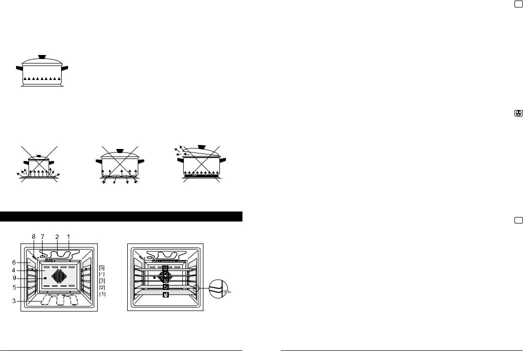
•El horno está equipado con guías en cinco niveles [1], [2], [3], [4] y [5] destinadas para colocar bandeja o rejilla con alimentos.
•En la parte superior del horno está instalada la resistencia superior 1 y la resistencia del grill 2, así como la lámpara que ilumina el interior del horno. Debajo del fondo (no visible) está la resistencia inferior 3.
•Las paredesv laterales del horno llevan montados grupos de guidas 5 y protecciones adicionales 6.
•En la pared trasera del horno está montada una proteccion especial perforada 4 y detrás de ella está colocada la resistencia circular y el ventilador, con lo que se consigue la circulation del aire.
•Las protecciones laterales 6 y la protección posterior 4 llevan una capa de esmalte catalítico de propiedades autolimpiantes.
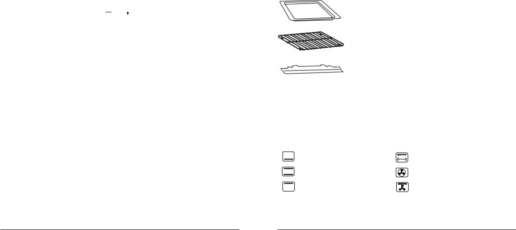
EQUIPAMIENTO
Bandeja esmaltada para pasteles. Se puede usar como depósito de recogida de grasa si la cocción se realiza directamente en la rejilla.
Rejilla sirve para depositar los recipientes que utilizamos en el horno. En la rejilla se pueden asar directamente algunos alimentos como biftecs, chorizos, pescados o tostadas.
Protección de mandos protege los mandos del calentamiento excesivo. Debe colocarse con la puerta entreabierta, durante la cocción en el horno.
Soporte del girapollos, sirve para fijar el mismo.
Fig. 13
4.2 MANDO SELECTOR DE FUNCIONES
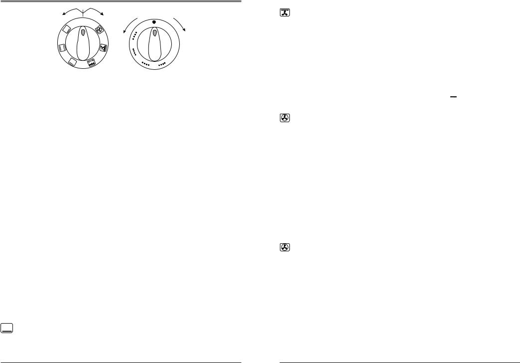
El mando dispone de siguientes posiciones:
0 - |
horno apagado |
|
|
- |
resistencia inferior |
- |
girapollos y resistencia del grill |
- |
resistencia inferior y superior |
- |
resistencia circular y ventilador |
- |
resistencia superior |
- |
resistencia de grill y ventilador |
•Después de posicionar el mando selector de funciones (figura 14) en la posición de trabajo, se enciende el piloto de control y la lámpara del horno.
•Después de terminar la cocción apague siempre el horno.
13
|
HORNO |
|
|
Sentido |
Sentido |
|
de apagado |
de encendido |
|
0 |
|
|
0 |
|
|
5 |
|
|
Fig. 14 |
Fig. 15 |
|
0 |
|
|
0 |
|
|
1 |
|
|
0 |
250 |
|
15 |
|
|
|
002 |
4.3 MANDO REGULADOR DE TEMPERATURA
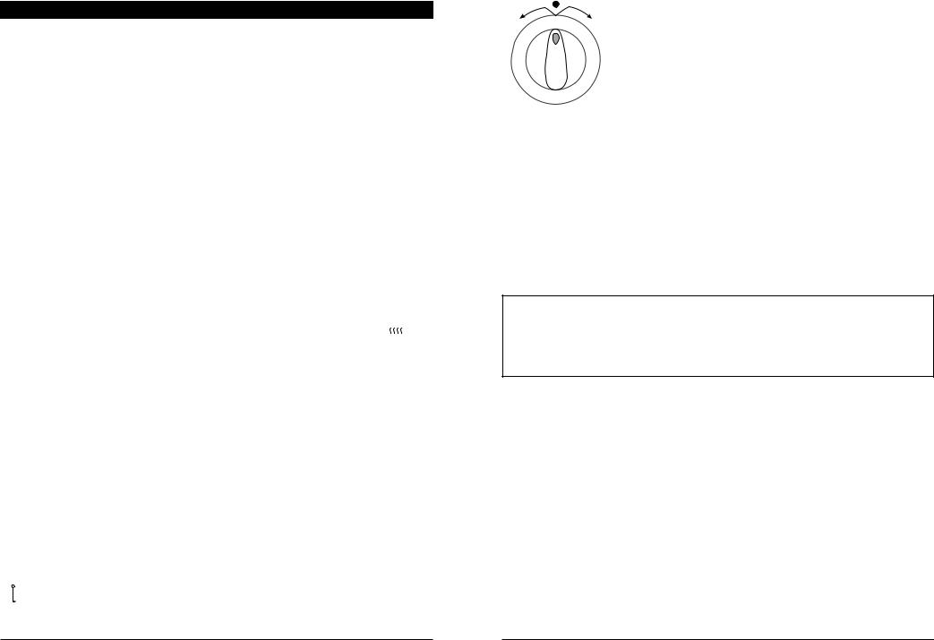
•El mando regulador de temperatura (Fig. 15) permite posicionar y mantener de forma automática la temperatura del horno a nivel preseleccionado.
•En el mando se han marcado las posiciones 50, 100, 150, 200, 250 que corresponden a las temperaturas del horno medidas en [oC].
•Al posicionar la temperatura, gire el mando en sentido horario y al apagar - en sentido antihorario.
•Después de posicionar la temperatura se activan las resistencias y se enciende el piloto de control. Al llegar a la temperatura deseada las resistencias y el piloto se apagan automáticamente. Las resistencias y el piloto se encienden y se apagan como consecuencia del funcionamiento del regulador de temperatura.
4.4 PROGRAMADOR ELECTRÓNICO
Con el programador electrónico es posible mandar el trabajo del horno de modo automático o semiautomático. La existencia del programador no elimina la posiblidad de mando manual de la cocina. Modo de empleo del programador se describe en adelante.
4.5 MANDO DEL HORNO
Entre los mandos del horno están:
–mando selector de funciones,
–mando regulador de temperatura,
–programador electrónico.
Cuando el alimento esté listo, gire el mando de selector de funciones y el mando regulador de temperatura hasta la posición cero 0.
4.6 MODALIDADES DE USO
CALENTAMIENTO CON LARESISTENCIAINFERIOR
Es la función que permite acabar la cocción de los pasteles. Se utiliza durante los últimos 10-15 minutos de cocción.
THE OVEN |
|
|
|
GRILLING WITH FORCED HEAT CIRCULATION ON
•This function is intended for broiling large meat portions (pork loin, chicken, etc.). In this case there is no need to preheat the oven.
•The food, in respect to their size, should be placed on the third or fourth level of the oven.
•This function allows for improving the taste of foods; so called "crisp crust" is also developed.
Operating procedure:
-place the meat in the oven,
-set the function change-over switch knob to position  ,
,
-set the required temperature and possibly time of grilling.
FORCED HEAT CIRCULATION
•Such a heating method allows for uniform heat circulation around the food. When using this heating method, the temperature should be slightly lower as compared to the traditional cooking. The temperature should be set below 200°C.
•The forced heat circulation function is ideal for simultaneous cooking of two dishes of the same or different kind (e.g. meat and fish), which are placed in the oven on two different levels; however, the two dishes should require similar cooking temperatures.
•At the end of cooking, the front side of baking tin should be preferably turned backwards.
•When baking the two dishes, the temperature should be slightly higher than recommended, and the time longer than at baking the single dish. When the set time has elapsed, remove both dishes from the oven, and make sure that they are sufficiently cooked. If one of the dishes requires further cooking, leave it in the oven until it is cooked properly.
DEFROSTING
Thanks to the forced heat circulation, the oven is ideal for defrosting deep frozen foods. Generally, we advise to place the frozen products on the plate located in the second or third oven level. Temperature selection for the defrosting process depends on the kind of frozen food.
•Confectionary, fruits and meat jelly are defrosted by starting the forced heat circulation without setting the temperature.
•While defrosting meat or poultry, wrap it with aluminium foil in order to prevent the direct effect of the hot air, and then place it in the middle or lower part of the oven compartment, turn the oven on, and set the temperature to approximately 50 - 70°C.
•Ready-to-use frozen products, e.g. frozen vegetables (wrapped with aluminium foil) can be baked immediately without defrosting.
14 |
16 |

|
THE OVEN |
|
|
|
TRADITIONAL GRILLING |
||
|
How to use the electric grill: |
||
C |
- put the dish in the oven, |
||
C |
|
|
|
|
- insert on the highest runner, |
||
|
- insert the drip tray on the bottom runner, |
||
|
- fit the knob protection screen and keep the oven |
||
|
|
door totally open (Fig. 15), |
|
|
- |
set the function change-over switch knob to |
|
|
|
position |
, |
|
- set the required temperature, |
||
|
- After half of the grilling time, turn the grilled |
||
|
|
portions over. |
|
|
When the grilling is over - turn the oven off. |
||
Fig. 15 Fitting the knob protection screen
GRILLING WITH ROASTING-SPIT
Roasting-spit is used to rotary grilling such dishes as poultry, sausages, etc.
How to handle the oven:
–remove all unnecessary outfit from the oven and slide in the roasting-spit frame;
–slide one fork onto the spit and stick meat onto it while paying attention it is symmetrical along the stick; then slide in the second fork and secure it in its position by tightening the set screw;
–insert the pointed end of spit into the roast-spit drive connection, push it home and rest the other end of spit on the frame;
–screw out the handle, install the knob protection screen and keep the oven door totally open;
–turn on the oven, adjust the temperature and, possibly, set the time of grilling.
1 |
Fig. 16 |
||
7 |
|||
|
|
||
2 |
1 |
- grill heater; |
|
6 |
2 - roasting-spit drive; |
||
4 |
3 |
- forks; |
|
8 |
4 |
- spit; |
|
3 |
5 |
- baking tray; |
|
5 |
6 |
- roasting-spit frame; |
|
7 - knob protection screen; |
|||
|
|||
|
8 |
- handle. |
|
The maximum weight of grilled portion should not exceed 3 kg. Grilling the average size chicken (weighing approximately 1 kg) takes approximately 50 - 60 minutes.
15
HORNO |
|
|
|
 SISTEMA CONVENCIONAL (resistencia superior e inferior)
La función con la que el alimento se calienta desde arriba y desde debajo. Este modo de calentamiento sirve perfectamente para asar pasteles, carnes, pescados, pan y pizza. Los alimentos deben colocarse en un solo nivel del horno, mejor en el segundo.
 CALENTAMIENTO CON LARESISTENCIASUPERIOR
Es la función destinada para grillar los asados; gracias a ella el pastel queda dorado por la parte superior. Este modo sirve también para gratinar alimentos (tostadas, guisos al gratín, etc.).
 GRILL
GRILL
Después de seleccionar la función  se pone en marcha la resistencia de grill y el motor de girapollos. Si el usuario no va usar el girapollos, hay que colocar el guiso en la rejilla o en la bandeja en una de las guías superiores y asar de forma tradicional.
GRILL TRADICIONAL
USO DEL GRILL
|
|
- precalentar el horno seleccionando la |
|
C |
C |
temperatura máxima, |
|
|
|
- colocar el alimento en el horno en la guía |
|
|
|
superior, |
|
|
|
- en la guía inferior colocar la bandeja que |
|
|
|
recogerá la grasa, |
|
|
|
- poner la protección de mandos y dejar la |
|
|
|
puerta abierta (figura 16), |
|
|
|
- poner el mando selector de funciones en |
|
|
|
la posición |
, |
|
|
- seleccionar la temperatura deseada y el |
|
|
|
tiempo del grill, |
|
|
|
- transcurrida la mitad del tiempo, darle |
|
|
|
vuelta al guiso. |
|
|
|
Terminado el asado con grill, apagar el horno. |
|
Fig. 16 Fijación de la protección de mandos
¡Atención!
Durante el asado con grill el aparato no debe dejarse sin control. Las partes accesibles de la cocina están calientes. Evitar el contacto de los niños.
15
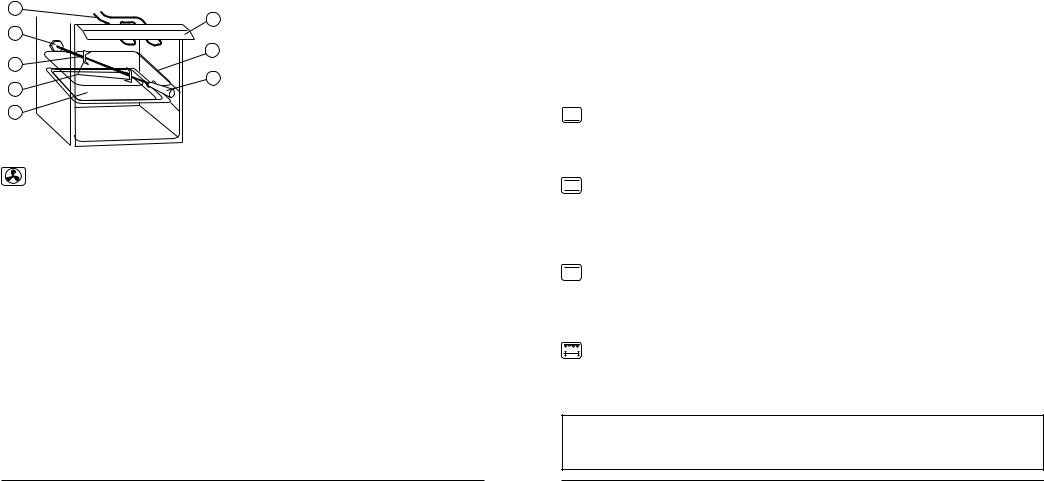
|
HORNO |
|
|
|
|
|
|
ASADO CON GIRAPOLLOS |
El girapollos sirve para asar girando los guisos como aves, chorizos, etc.
Funcionamiento del horno:
-quitar del horno todo el equipamiento innecesario y montar el soporte del girapollos,
-en el espadín del girapollos montar uno de los pinchos y pinchar el guiso para que quede fijado de forma simétrica; luego pinchar con el segundo pincho y fijarlo bien apretando el tornillo del pincho,
-colocar el guiso preparado de esta forma introduciendo el extremo agudo en el motor girapollos y apretando a tope y apoyar el otro extremo en el marco,
-desenroscar el mango, poner la protección de mandos y dejar la puerta abierta,
-poner el horno en marcha, seleccionar la temperatura y el tiempo de trabajo.
1 |
Fig. 17 |
||
7 |
|||
|
|
||
2 |
1 |
- resistencia del grill; |
|
6 |
2 |
- motor del girapollos; |
|
4 |
3 - pinchos; |
||
|
8 |
4 - espadín del girapollos; |
3 |
|
|
|
5 - bandeja (depósito de grasa); |
|
|
|
|
5 |
|
6 - soporte del girapollos; |
|
|
|
|
|
7 - protección de mandos; |
|
|
8 - mango del girapollos. |
TERMOVENTILACIÓN
•El funcionamiento de termoventilación consiste en la circulación de aire forzada por el ventilador dentro de la cámara del horno. Con este método de asado hay que seleccionar la temperatura más baja en el asado tradicional, por debajo de 2000C.
•Al final de asado, es aconsejable girar el molde con su parte delantera para atrás.
•La función de termoventilación sirve perfectamente para el asado paralelo de dos guisos del mismo o del distinto tipo (ej. carne y pescado) colocados en distintos niveles pero cocinados a la misma temperatura. Al cocinar dos guisos es aconsejable subir la temperatura respecto al valor indicado para un solo guiso.
•Para asar y cocinar carnes es aconsejable escoger trozos más grandes, superiores a 1 kg.
En caso de cocción simultánea de dos guisos:
–Hay que sacar del horno los dos guisos y verificar si están hechos; si uno de los guisos queda sin hacerse, hay que volver a colocarlo en el horno y seguir cocinando.
THE OVEN |
|
|
|
4.5 ELECTRONIC PROGRAMMER
The electronic programmer allows you to control the oven operation in the automatic and semi-automatic cycle.
After completing each programme, the electronic timer emits an audible sound and automatically turns the oven off.
The electronic timer does not exclude possibility of manual control of the oven operation. The programming procedure is described in further parts of the instructions.
4.6 TURNING THE OVEN ON AND OFF
4.6.1 TURNING THE OVEN ON
1.Set the cooking method with the function selector.
2.Set the temperature with the temperature selector.
3.Programme the time of oven operation.
4.6.2 TURNING THE OVEN OFF
Always remember to set the function and temperature selector back to 0 when you finish using the oven.
4.7 COOKING METHODS
LOWER HEATER TURNED ON
This function allows for extra heating of the cake bottom. It is used during the last 10 - 15 minutes of the dish stay in the oven.
CONVENTIONAL SYSTEM (lower heater and upper heater turned on)
With this function, dishes are heated from the bottom and from the top. This kind of heating is ideal for cooking cakes, meat, fish, pizza and bread. The dishes should be placed on a single, preferably middle level of the oven.
UPPER HEATER TURNED ON
The function is intended for baking finish. Thanks to this function the dish can be browned from the top. This heating method can also be used for fast cooking (toasts, casseroles).
GRILLING
After selecting this function, the grill heater and turnspit drives are turned on. If the user does not intend to use the turnspit, the dish should be placed on the grate shelf, or directly under the grill heater and grilled in the traditional manner.
WARNING !
While grilling, the appliance must not be left without supervision. Accessible parts of the cooker are very hot ! Keep children well away.
16 |
14 |
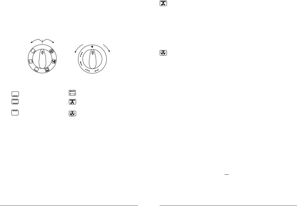
|
THE OVEN |
|
|
4.2 OVEN CONTROLS
Operation of the oven is controlled with the use of:
–function change-over switch knob,
–temperature control knob,
–electronic programmer.
4.3FUNCTION SELECTOR
|
Turn-off |
Turn-on |
|
direction |
direction |
|
0 |
|
|
0 |
|
|
5 |
|
Fig. 13 |
0 |
Fig. 14 |
1 |
||
|
0 |
|
|
1 |
25 |
|
50 |
0 |
|
002 |
|
The following functions can be selected: |
|
|
0 - oven turned off |
|
|
- lower heater |
- grill and roasting-spit |
|
- Conventional Heating |
- grill and fan |
|
(lower and upper heater) |
|
|
- upper heater |
- circulater heater and fan |
|
•On selecting a function the appropriate indicator light will come on and the oven light will also come on.
•Always turn the function selector back to 0 when you have finished using the oven.
4.4 TEMPERATURE SELECTOR
•The temperature control knob (Fig. 14) allows for setting and automatically maintaining the oven inside temperature on the set level.
•On the knob there are following settings - 50, 100, 150, 200, and 250, which correspond to the selected temperatures in [°C].
•When selecting the temperature - turn the knob in the clockwise direction, to switch the control off - turn in the opposite direction.
•On selecting a temperature, the control light will come on. When reaching the set temperature, the heaters are automatically turned off and the indicator lamp goes out. The heaters and indicator lamp are turned on and off as a result of temperature controller operation.
13
|
|
HORNO |
|
|
|
|
|
|
|
GRILL CON VENTILACIÓN DE AIRE CALIENTE |
|
|
|
|
•Esta función sirve para asar en la rejilla las grandes raciones de carne (solomillo, lomo, aves enteras como pollos, ocas, etc.) En este caso no es necesario precalentar el horno. El tiempo de asado es reducido en un 20% respecto al asado tradicional.
•Los guisos hay que colocar en el tercero o cuarto nivel del horno en función de su tamano.
•Gracias a esta función es posible mejorar el sabor de los guisos y consegui la piel bien dorada.
DESCONGELACIÓN
Gracias a la función de termoventilación el horno sirve también para descogelar alimentos profundamente congelados. Se aconseja colocar los productos congelados en la bandeja a nivel dos o tres. La temperatura seleccionada para la descongelación depende del tipo de alimento.
•Dulces, frutas y gelatinas de carne se descongelan accionando la termoventilación sin seleccionar la temperatura.
•Descongelando carnes y aves hay que envolverlas con lámina de aluminio para proteger contra la influencia directa del aire caliente, colocarlas en la parte central baja, accionar el horno y seleccionar la temperatura de 50 a 700C.
•Los guios preparados para comer, ej. verduras (embalados con de aluminio) se pueden asar sin descongelación previa.
4.7 INDICACIONES REFERIDAS AL ASADO
•Para el asado de pasteles se pueden usar moldes tradicionales de chapa así como moldes cubiertos de teflón, cerámicos, de vidrio y de aluminio.
•Antes de usarlos por primera vez, es aconsejable colocar los moldes en el horno bien calentado para que pierda su olor.
•Los moldes hay que rellenarlos con la masa hasta 2/3 de altura, dejando suficiente espacio para que puedan crecer.
•Hay que seguir estrictamente las indicaciones respecto al precalentamiento del horno puesto que para cada tipo de pastel las exigencias son distintas.
•Durante el asado la masa tiene que calentarse de forma homogénea. Esta condición se cumple al seleccionar la función  ó
ó  .
.
•Si la parte superior del pastel queda demasiado quemada, la próxima vez hay que colocar el molde con la masa en un nivel más bajo, seleccionar la temperatura más reducida y el tiempo de cocción más largo.
•Si la parte inferior del pastel queda demasiado quemada, la próxima vez hay que colocar el molde más arriba y seleccionar la temperatura más baja.
17
 Loading...