


Instruction Manual |
4195K Controllers |
D200160X012 |
December 2012 |
|
|
Fisherr 4195KA, KB, KC, and KS Gauge Pressure
Controllers
Contents
1. Introduction
Scope of Manual . . . . . . . . . . . . . . . . . . . . . . . . . . . . . 4 Description . . . . . . . . . . . . . . . . . . . . . . . . . . . . . . . . . 4 Specifications . . . . . . . . . . . . . . . . . . . . . . . . . . . . . . . 4 Educational Services . . . . . . . . . . . . . . . . . . . . . . . . . 4
2. Installation
Controller Mounting Orientation . . . . . . . . . . . . . . . 9 Pipestand Mounting . . . . . . . . . . . . . . . . . . . . . . . . . 9 Panel Mounting . . . . . . . . . . . . . . . . . . . . . . . . . . . . 10 Wall Mounting . . . . . . . . . . . . . . . . . . . . . . . . . . . . . 11 Actuator Mounting . . . . . . . . . . . . . . . . . . . . . . . . . 11 Pressure Connections . . . . . . . . . . . . . . . . . . . . . . . 12
Process Pressure Connection . . . . . . . . . . . . . . 12 Supply Pressure Connection . . . . . . . . . . . . . . 12 Remote Set Point (suffix letter M)
Pressure Connection . . . . . . . . . . . . . . . . . . 13 External Feedback Pressure Connection
(4195KB Controllers Only) . . . . . . . . . . . . . 13 Vent . . . . . . . . . . . . . . . . . . . . . . . . . . . . . . . . . . . . . . 14
3. 4195KA Proportional Only Controllers
Adjustments for 4195KA Controllers . . . . . . . . . . . 15 Manual Set Point Adjustment . . . . . . . . . . . . . 15 Remote Set Point (suffix letter M)
Adjustment . . . . . . . . . . . . . . . . . . . . . . . . . . 16 Proportional Band Adjustment (PB ADJ) . . . . . 16 Changing Controller Action . . . . . . . . . . . . . . . 16 Switching The Auto/Manual Station
(suffix letter E) . . . . . . . . . . . . . . . . . . . . . . . 17 Prestartup Checks for 4195KA Controllers . . . . . . 17 Startup for 4195KA Controllers . . . . . . . . . . . . . . . 18 Calibration of 4195KA Controllers . . . . . . . . . . . . . 18 General Calibration Instructions . . . . . . . . . . . 19 Process Indicator Zero and Span Calibration . 19
Remote Set Point (suffix letter M)
Zero and Span Calibration . . . . . . . . . . . . . . 21 Flapper Alignment . . . . . . . . . . . . . . . . . . . . . . 22 Principle of Operation for 4195KA Controllers . . . 23 Overall Operation . . . . . . . . . . . . . . . . . . . . . . . 23
Remote Set Point (suffix letter M)
Operation . . . . . . . . . . . . . . . . . . . . . . . . . . . 24 Auto/Manual Station (suffix letter E)
Operation . . . . . . . . . . . . . . . . . . . . . . . . . . . 24
4. 4195KB Proportional Plus Reset Controllers and 4195KC Proportional Plus Reset Plus Rate Controllers
Adjustments for 4195KB and KC Controllers . . . . . 25 Manual Set Point Adjustment . . . . . . . . . . . . . 25 Remote Set Point (suffix letter M)
Adjustment . . . . . . . . . . . . . . . . . . . . . . . . . . 26 Proportional Band Adjustment (PB ADJ) . . . . . 26 Changing Controller Action . . . . . . . . . . . . . . . 26 Reset Adjustment . . . . . . . . . . . . . . . . . . . . . . . 27 Rate Adjustment . . . . . . . . . . . . . . . . . . . . . . . . 27 Anti Reset Windup (suffix letter F)
Adjustment . . . . . . . . . . . . . . . . . . . . . . . . . . 27 Switching the Auto/Manual Station
(suffix letter E) . . . . . . . . . . . . . . . . . . . . . . . 27 Prestartup Checks for 4195KB and KC
Controllers . . . . . . . . . . . . . . . . . . . . . . . . . . . . . . 28 Startup for 4195KB and KC Controllers . . . . . . . . . 28 Calibration of 4195KB and KC Controllers . . . . . . . 30 General Calibration Instructions . . . . . . . . . . . 30
Process Indicator Zero and Span
Calibration . . . . . . . . . . . . . . . . . . . . . . . . . . 30 Remote Set Point (suffix letter M)
Zero and Span Calibration . . . . . . . . . . . . . . 32 Flapper Alignment . . . . . . . . . . . . . . . . . . . . . . 33 Anti Reset Windup (suffix letter F)
Differential Relief Valve Calibration . . . . . . 35 Principle of Operation for 4195KB and KC
Controllers . . . . . . . . . . . . . . . . . . . . . . . . . . . . . . 36 Overall Operation . . . . . . . . . . . . . . . . . . . . . . . 36 Anti Reset Windup (suffix letter F)
Operation . . . . . . . . . . . . . . . . . . . . . . . . . . . 39 Remote Set Point (suffix letter M)
Operation . . . . . . . . . . . . . . . . . . . . . . . . . . . 39 Auto/Manual Station (suffix letter E)
Operation . . . . . . . . . . . . . . . . . . . . . . . . . . . 40 External Feedback Operation . . . . . . . . . . . . . . 41
5. 4195KS Differential Gap Controllers |
|
Operating Information . . . . . . . . . . . . . . . . . . . . . . |
42 |
Adjustments for 4195KS Differential Gap |
|
Controllers . . . . . . . . . . . . . . . . . . . . . . . . . . . . . . |
43 |
Manual Set Point . . . . . . . . . . . . . . . . . . . . . . . . |
43 |
Remote Set Point (Option M) . . . . . . . . . . . . . |
43 |
Proportional Band (Differential Gap) . . . . . . . |
43 |
Changing Controller Action . . . . . . . . . . . . . . . |
43 |
www.Fisher.com
4195K Controllers |
Instruction Manual |
December 2012 |
D200160X012 |
|
|
Contents (continued) |
|
Auto/Manual Switching (Option E) . . . . . . . . . |
44 |
Prestartup Checks . . . . . . . . . . . . . . . . . . . . . . . . . . |
44 |
Startup . . . . . . . . . . . . . . . . . . . . . . . . . . . . . . . . . . . |
44 |
Calibration . . . . . . . . . . . . . . . . . . . . . . . . . . . . . . . . |
45 |
Process Zero and Span Adjustment . . . . . . . . |
45 |
Remote Set Point Zero and Span |
|
(Option M) . . . . . . . . . . . . . . . . . . . . . . . . . . |
45 |
Setting Switching Points . . . . . . . . . . . . . . . . . |
46 |
Direct Acting Controllers . . . . . . . . . . . . . . . . . |
46 |
Reverse Acting Controllers . . . . . . . . . . . . . . . |
48 |
Principle of Operation . . . . . . . . . . . . . . . . . . . . . . . |
48 |
Overall Operation . . . . . . . . . . . . . . . . . . . . . . . |
48 |
Remote Set Point (Option M) . . . . . . . . . . . . . |
50 |
Auto/Manual Option . . . . . . . . . . . . . . . . . . . . . |
50 |
6. Maintenance |
|
Inspection and Maintenance . . . . . . . . . . . . . . . . . . |
51 |
Troubleshooting . . . . . . . . . . . . . . . . . . . . . . . . . . . . |
51 |
Replacing Common Controller Parts . . . . . . . . . . . |
55 |
Replacing the Process Pressure Scale . . . . . . . |
55 |
Replacing the Relay . . . . . . . . . . . . . . . . . . . . . |
56 |
Replacing the Case and Cover . . . . . . . . . . . . . |
56 |
Replacing the Gauges . . . . . . . . . . . . . . . . . . . . |
57 |
Replacing the Supply Gauge, Proportional, |
|
Reset, Reset Valve and Positive Tubing |
|
Feedback Assemblies . . . . . . . . . . . . . . . . . . |
58 |
Replacing the Proportional Band Adjustment |
|
Knob, Nozzle Assembly, and Set Point |
|
Beam Assembly . . . . . . . . . . . . . . . . . . . . . . |
58 |
Replacing the Flapper Assembly and |
|
Flapper Flexure Pivot Assembly . . . . . . . . . |
63 |
Replacing the Proportional or Reset |
|
Bellows . . . . . . . . . . . . . . . . . . . . . . . . . . . . . |
68 |
Replacing the Reset Restriction Valve |
|
(4195KB Controllers) . . . . . . . . . . . . . . . . . . |
70 |
Replacing the Rate/Reset Valve Assembly |
|
(4195KC Controllers) . . . . . . . . . . . . . . . . . . |
71 |
Replacing the Anti Reset Windup |
|
(suffix letter F) Differential Relief Valve . . . |
72 |
Replacing the Anti Reset Windup |
|
(suffix letter F) Relief Valve Tubing |
|
Assembly . . . . . . . . . . . . . . . . . . . . . . . . . . . . |
72 |
Bourdon Tube Controller Maintenance |
|
and Calibration . . . . . . . . . . . . . . . . . . . . . . . . . . |
73 |
Replacing the Bourdon Tube . . . . . . . . . . . . . . |
73 |
Replacing Bourdon Tube Controller Links . . . |
74 |
ÃReplacing Link 1 . . . . . . . . . . . . . . . . . . . . . . |
74 |
ÃReplacing Link 2 . . . . . . . . . . . . . . . . . . . . . . |
75 |
ÃReplacing Link 3 . . . . . . . . . . . . . . . . . . . . . . |
76 |
ÃReplacing Link 4 . . . . . . . . . . . . . . . . . . . . . . |
77 |
Bourdon Tube Travel Stop Installation |
|
and Adjustment . . . . . . . . . . . . . . . . . . . . . . |
78 |
Bourdon Tube Controller Calibration: |
|
Zero and Span Adjustment . . . . . . . . . . . . . |
79 |
Capsular Element Controller Maintenance |
|
and Calibration . . . . . . . . . . . . . . . . . . . . . . . . . . |
82 |
Replacing the Capsular Element |
|
ÃAssembly . . . . . . . . . . . . . . . . . . . . . . . . . . |
82 |
ÃReplacing Capsular Element Parts . . . . . . . . |
83 |
ÃReplacing the Long Pivot Assembly . . . . . . |
83 |
ÃReplacing the Short Pivot Assembly . . . . . . |
84 |
ÃReplacing the Process Drive Flexure . . . . . . |
84 |
ÃReplacing the Process Tubing . . . . . . . . . . . |
85 |
Replacing Capsular Element |
|
ÃController Links . . . . . . . . . . . . . . . . . . . . |
85 |
ÃReplacing Link 1 . . . . . . . . . . . . . . . . . . . . . . |
86 |
ÃReplacing Link 2 . . . . . . . . . . . . . . . . . . . . . . |
86 |
ÃReplacing Link 3 . . . . . . . . . . . . . . . . . . . . . . |
87 |
ÃReplacing Link 4 . . . . . . . . . . . . . . . . . . . . . . |
87 |
ÃReplacing Link 5 . . . . . . . . . . . . . . . . . . . . . . |
88 |
Capsular Element Controller |
|
Maintenance Calibration . . . . . . . . . . . . . . . |
88 |
ÃPrecalibration Procedure . . . . . . . . . . . . . . . |
89 |
ÃAligning the Drive Bracket Assembly . . . . . |
89 |
ÃSetting the Travel Stops . . . . . . . . . . . . . . . . |
89 |
ÃAligning the Linkage . . . . . . . . . . . . . . . . . . . |
90 |
ÃCapsular Element Controller |
|
Zero and Span Adjustment . . . . . . . . . . . . . |
91 |
Remote Set Point (suffix letter M) |
|
Maintenance . . . . . . . . . . . . . . . . . . . . . . . . . . . . |
92 |
Replacing the Remote Set Point |
|
Assembly . . . . . . . . . . . . . . . . . . . . . . . . . . . . |
92 |
Replacing Remote Set Point |
|
ÃAssembly Parts . . . . . . . . . . . . . . . . . . . . . |
94 |
ÃReplacing Pivot Assembly A (key 114) . . . . |
94 |
ÃReplacing Pivot Assembly B (key 115) . . . . |
95 |
ÃReplacing the Drive Flexure . . . . . . . . . . . . . |
95 |
ÃReplacing the Remote Set Point Tubing . . . |
96 |
ÃReplacing Link A . . . . . . . . . . . . . . . . . . . . . . |
96 |
ÃReplacing Link B . . . . . . . . . . . . . . . . . . . . . . |
96 |
Remote Set Point (suffix letter M) |
|
Maintenance Calibration . . . . . . . . . . . . . . . . . . |
96 |
Precalibration Procedure . . . . . . . . . . . . . . . . . |
96 |
Aligning the Flexures . . . . . . . . . . . . . . . . . . . . |
97 |
Setting the Travel Stops . . . . . . . . . . . . . . . . . . |
97 |
Aligning the Linkage . . . . . . . . . . . . . . . . . . . . . |
98 |
Remote Set Point Zero and Span |
|
Adjustment . . . . . . . . . . . . . . . . . . . . . . . . . . |
98 |
Remote Set Point Linearity Adjustment . . . . . |
99 |
Auto/Manual Station (suffix letter E) |
|
Maintenance . . . . . . . . . . . . . . . . . . . . . . . . . . . |
100 |
Replacing the Auto/Manual Station . . . . . . . |
100 |
Replacing the Switch Body Assembly, |
|
Lever O Ring, Switch Body O Ring, |
|
and Tubing Assembly . . . . . . . . . . . . . . . . |
101 |
Replacing the Loader Range Spring, |
|
Diaphragm Assembly, Ball Seat, |
|
Tubing, and Ball . . . . . . . . . . . . . . . . . . . . . |
102 |
Replacing the Loader Valve Plug and |
|
Valve Plug Spring . . . . . . . . . . . . . . . . . . . . |
103 |
2
Instruction Manual |
4195K Controllers |
D200160X012 |
December 2012 |
|
|
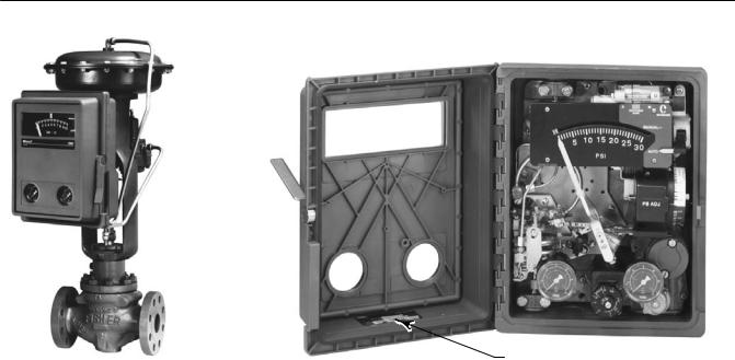
Figure 1-1. Fisher 4195K Gauge Pressure Controllers
NAMEPLATE
W5663 1 |
W6831 |
|
|
Contents (continued) |
|
7. Parts |
|
Parts Ordering . . . . . . . . . . . . . . . . . . . . . . . . . . . . |
105 |
Parts Kits . . . . . . . . . . . . . . . . . . . . . . . . . . . . . . . . . |
105 |
Parts List . . . . . . . . . . . . . . . . . . . . . . . . . . . . . . . . . |
105 |
Abbreviations Used In The Parts List . . . . . . . |
105 |
Controller Common Parts . . . . . . . . . . . . . . . |
106 |
Process and Set Point Indicator |
|
Assembly . . . . . . . . . . . . . . . . . . . . . . . . . . . |
114 |
Indicator Assembly . . . . . . . . . . . . . . . . . . . . . |
116 |
Capsular Element Assembly . . . . . . . . . . . . . . |
118 |
Remote Set Point Assembly |
|
(suffix letter M) . . . . . . . . . . . . . . . . . . . . . . |
119 |
Auto/Manual Station (suffix letter E) . . . . . . . |
120 |
Controller Mounting Parts . . . . . . . . . . . . . . . |
122 |
ÃPipestand Mounting . . . . . . . . . . . . . . . . . . |
122 |
ÃPipestand Mounting with Regulator . . . . . |
122 |
ÃPanel Mounting . . . . . . . . . . . . . . . . . . . . . . 122 ÃWall Mounting . . . . . . . . . . . . . . . . . . . . . . . 122 ÃController Mounting Parts for Actuator
Ãwith Casing Mounted Controller . . . . . 122 ÃController Mounting Parts for Actuator
Ãwith Yoke Mounted Controller . . . . . . . 122 Regulator Mounting Parts . . . . . . . . . . . . . . . 123 ÃRegulator Mounting Parts for
ÃCasing Mounted Regulator . . . . . . . . . . 123 ÃRegulator Mounting Parts for
ÃYoke Mounted Regulator (Mounting ÃBracket Not Required) . . . . . . . . . . . . . . 123
ÃRegulator Mounting Parts for ÃYoke Mounted Regulator
Ã(With Mounting Bracket) . . . . . . . . . . . . 123 Fittings . . . . . . . . . . . . . . . . . . . . . . . . . . . . . . . 123
3
4195K Controllers |
Instruction Manual |
December 2012 |
D200160X012 |
|
|
Section 1 Introduction
Scope of Manual
This instruction manual provides installation, operating, calibration, maintenance, and parts ordering information for Fisher 4195KA, KB, KC, and KS gauge pressure indicating controllers.
Portions of this manual apply only to specific 4195K controller configurations. These configurations are indicated by letter suffixes in the type number that correspond to the mode and option designated in table 1-2.
The specific controller type number (with letter suffixes) is located on the nameplate shown in figure 1-1. Refer to table 1-2 for the definition of each 4195K type number.
Do not install, operate, or maintain a 4195K controller without being fully trained and qualified in valve, actuator, and accessory installation, operation, and maintenance. To avoid personal injury or property damage, it is important to carefully read, understand, and follow all the contents of this manual, including all safety cautions and warnings. If you have any questions about these instructions, contact your Emerson Process Management sales office before proceeding.
Description
The controllers described in this manual provide gauge pressure control with the options as shown in table 1-2.
D 4195KA: Proportional only control
D 4195KB: Proportional plus reset control
D 4195KC: Proportional plus reset plus rate control
D 4195KS: Differential gap control
These controllers show process pressure and set point on an easy to read process scale. The controller output is a pneumatic signal that operates a final control element.
Specifications
Specifications for 4195KA, KB, KC, and KS controllers are listed in table 1-1.
Educational Services
For information on available courses for 4195KA, 4195KB, 4195KC, and 4195KS gauge pressure indicating controllers, as well as a variety of other products, contact:
Emerson Process Management Educational Services, Registration P.O. Box 190; 301 S. 1st Ave. Marshalltown, IA 50158-2823 Phone: 800-338-8158 or
Phone: 641-754-3771 FAX: 641-754-3431
e mail: education@emerson.com
4

Instruction Manual |
4195K Controllers |
D200160X012 |
December 2012 |
|
|
Table 1-1. Specifications
Available Configurations
See table 1-2
Input Signal (Process Sensor Range)
Lower and Upper Range Limits: See tables 1-3 and 1-4 Maximum Allowable Operating Limits: See tables 1-3 and 1-4
Output Signal
Proportional Only, Proportional Plus Reset, or Proportional Plus Reset Plus Rate Range: 0.2 to 1.0 bar or 0.4 to 2.0 bar (3 to 15 psig or 6 to 30 psig) Differential Gap Range: 0 and 1.4 bar (0 and 20 psig) or 0 and 2.4 bar (0 and 35 psig)
Action: Field reversible between direct (increasing sensed process pressure increases output pressure) or reverse (increasing sensed process pressure decreases output pressure).
Process Scale
Standard scale is matched to the range of the sensing element, with the exception of receiver controllers. Optional(1) scales are available.
Process Connections
Standard: 1/4 NPT, internal, stainless steel (all input ranges)
Optional: 1/2 NPT, see table 1-5
Supply and Output Connections
1/4 NPT, internal
Supply Pressure Requirements(2)
See table 1-6
Supply Pressure Medium
Air or natural gas
Air: Supply pressure must be clean, dry air that meets the requirements of ISA Standard 7.0.01. A maximum 40 micrometer particle size in the air system is acceptable. Further filtration down to 5 micrometer particle size is recommended. Lubricant content is not to exceed 1 ppm weight (w/w) or volume (v/v) basis. Condensation in the air supply should be minimized.
Natural Gas: Natural gas must be clean, dry, oil free, and noncorrosive. H2S content should not exceed 20 ppm.
Remote Set Point Pressure Ranges
0.2 to 1.0 bar or 0.4 to 2.0 bar (3 to 15 psig or 6 to 30 psig)
Controller Adjustments
Proportional Band: 5 to 500% of process input span Reset: Adjustable from 0.01 to more than 74 minutes per repeat (from 100 to less than 0.0135 repeats per minute)
Rate: Adjustable from 0 to 20 minutes
Differential Gap Controllers: Adjustable from 5 to 100% of process scale range
Set Point: Adjustable from 0 to 100% of the scale span
Controller Performance
Repeatability: 0.4% of output span
Dead Band: Less than 0.4% of process scale span
Typical Frequency Response: 1.5 hertz and 90 degree phase shift with 3.05 m (10 feet) of 6.4 mm (1/4 inch) tubing and 1639 cm3 (100 cubic inch) volume
Steady State Air Consumption(3)(4)
0.2 to 1.0 Bar (3 to 15 Psig) Output:
0.1normal m3/hr (3.5 scfh)
0.4to 2.0 Bar (6 to 30 Psig) Output:
0.14normal m3/hr (5.0 scfh)
Delivery Capacity(3)
0.2 to 1.0 Bar (3 to 15 Psig) Output:
5.9normal m3/hr (240 scfh)
0.4to 2.0 Bar (6 to 30 Psig) Output:
10.4normal m3/hr (350 scfh)
Operative Ambient Temperature Limits(2)(5)
-40 to 71_C (-40 to 160_F)
Exhaust Capacity(3)
0.2 to 1.0 Bar (3 to 15 Psig) Output:
4.6normal m3/hr (186 scfh)
0.4to 2.0 Bar (6 to 30 Psig) Output:
7.0normal m3/hr (295 scfh)
Hazardous Area Classification
Complies with the requirements of ATEX Group II Category 2 Gas and Dust
-continued-
5

4195K Controllers |
Instruction Manual |
December 2012 |
D200160X012 |
|
|
Table 1-1. Specifications (continued)
Housing
Designed to NEMA 3 (Weatherproof) and IEC 529
IP54 Specifications
Mounting
Controller can be mounted on actuator, panel, wall, or pipestand.
Approximate Weight
4.5 kg (10 pounds)
Declaration of SEP
Fisher Controls International LLC declares this product to be in compliance with Article 3 paragraph 3 of the Pressure Equipment Directive (PED) 97 / 23 / EC. It was designed and manufactured in accordance with Sound Engineering Practice (SEP) and cannot bear the CE marking related to PED compliance.
However, the product may bear the CE marking to indicate compliance with other applicable EC Directives.
NOTE: Specialized instrument terms are defined in ANSI/ISA Standard 51.1 - Process Instrument Terminology.
1.Consult your Emerson sales office for additional information.
2.The pressure/temperature limits in this document and any applicable standard or code limitation should not be exceeded.
3.Normal m3/hr—Normal cubic meters per hour (0_C and 1.01325 bar, absolute). Scfh—Standard cubic feet per hour (60_F and 14.7 psia).
4.Without auto/manual station. With auto/manual station, air consumption is 0.28 normal m3/hr (10.0 Scfh) for either output range.
5.Also use these temperatures for transportation and storage limits.
Table 1-2. Available Configurations for Fisher 4195KA, 4195KB, 4195KC, and 4195KS Controllers
|
|
|
MODES |
|
|
OPTIONS |
|
|
||
|
|
Proportional |
Proportional |
Proportional |
|
Internal |
|
|
|
|
|
TYPE |
Plus Reset |
|
Anti Reset |
Remote |
|
||||
CONTROLLER |
Only |
Plus Reset |
Differential |
Auto/Manual |
|
|||||
NUMBER(1) |
Plus Rate |
Windup |
Setpoint |
|
||||||
|
(One Mode |
(Two Mode |
Gap Controller |
Station |
|
|||||
|
|
(Three Mode |
F |
M |
|
|||||
|
|
Controllers) |
Controllers) |
|
E |
|
||||
|
|
Controllers) |
|
|
|
|
||||
|
|
|
|
|
|
|
|
|
||
|
4195KA |
X |
- - - |
- - - |
- - - |
- - - |
- - - |
- - - |
|
|
4195KA |
4195KAE |
X |
- - - |
- - - |
- - - |
X |
- - - |
- - - |
|
|
4195KAM |
X |
- - - |
- - - |
- - - |
- - - |
- - - |
X |
|||
|
||||||||||
|
4195KAME |
X |
- - - |
- - - |
- - - |
X |
- - - |
X |
||
|
|
|
|
|
|
|
|
|
|
|
|
4195KB |
- - - |
X |
- - - |
- - - |
- - - |
- - - |
- - - |
|
|
|
4195KBE |
- - - |
X |
- - - |
- - - |
X |
- - - |
- - - |
|
|
|
4195KBF |
- - - |
X |
- - - |
- - - |
- - - |
X |
- - - |
|
|
4195KB |
4195KBFE |
- - - |
X |
- - - |
- - - |
X |
X |
- - - |
|
|
4195KBM |
- - - |
X |
- - - |
- - - |
- - - |
- - - |
X |
|||
|
||||||||||
|
4195KBME |
- - - |
X |
- - - |
- - - |
X |
- - - |
X |
||
|
4195KBFM |
- - - |
X |
- - - |
- - - |
- - - |
X |
X |
||
|
4195KBFME |
- - - |
X |
- - - |
- - - |
X |
X |
X |
||
|
|
|
|
|
|
|
|
|
|
|
|
4195KC |
- - - |
- - - |
X |
- - - |
- - - |
- - - |
- - - |
|
|
|
4195KCE |
- - - |
- - - |
X |
- - - |
X |
- - - |
- - - |
|
|
|
4195KCF |
- - - |
- - - |
X |
- - - |
- - - |
X |
- - - |
|
|
4195KC |
4195KCFE |
- - - |
- - - |
X |
- - - |
X |
X |
- - - |
|
|
4195KCM |
- - - |
- - - |
X |
- - - |
- - - |
- - - |
X |
|||
|
||||||||||
|
4195KCME |
- - - |
- - - |
X |
- - - |
X |
- - - |
X |
||
|
4195KCFM |
- - - |
- - - |
X |
- - - |
- - - |
X |
X |
||
|
4195KCFME |
- - - |
- - - |
X |
- - - |
X |
X |
X |
||
|
|
|
|
|
|
|
|
|
|
|
|
4195KS |
- - - |
- - - |
- - - |
X |
- - - |
- - - |
- - - |
|
|
4195KS |
4195KSE |
- - - |
- - - |
- - - |
X |
X |
- - - |
- - - |
|
|
4195KSM |
- - - |
- - - |
- - - |
X |
- - - |
- - - |
X |
|||
|
||||||||||
|
4195KSME |
- - - |
- - - |
- - - |
X |
X |
- - - |
X |
||
|
|
|
|
|
|
|
|
|
|
|
1. Reverse acting constructions are designated by the suffix letter R added to the type number.
6

Instruction Manual |
|
|
|
|
4195K Controllers |
|
||||||
D200160X012 |
|
|
|
|
|
|
|
|
December 2012 |
|
||
|
|
|
|
|
|
|
|
|
|
|
||
Table 1-3. Process Sensor (Capsular Element) Pressure Ratings |
|
|
|
|
|
|
||||||
|
|
|
|
|
|
|
|
|
|
|
|
|
CAPSULE |
|
|
CAPSULAR |
|
SPAN(1) |
OPERATING RANGE |
|
OPERATING |
|
|||
MATERIAL |
|
|
STANDARD RANGES |
Min |
Max |
Min |
Max |
|
LIMIT(2) |
|
||
|
|
|
|
|
0 to 150 mbar |
100 mbar |
160 mbar |
-350 mbar |
350 mbar |
|
510 mbar |
|
|
|
|
|
|
0 to 400 mbar |
350 mbar |
700 mbar |
-1 bar |
1 bar |
|
1.5 bar |
|
|
|
|
|
|
0 to 0.6 bar |
0.35 bar |
0.7 bar |
-1 bar |
1 bar |
|
1.5 bar |
|
|
|
|
|
|
0.2 to 1 bar |
0.4 bar |
0.8 bar |
-1 bar |
1.4 bar |
|
2 bar |
|
|
|
|
Positive pressure |
|
0 to 1 bar |
0.5 bar |
1 bar |
-1 bar |
1.4 bar |
|
2 bar |
|
|
|
|
|
|
0 to 1.4 bar |
0.7 bar |
1.4 bar |
-1 bar |
1.7 bar |
|
2.5 bar |
|
|
|
|
|
|
0 to 1.6 bar |
1 bar |
2 bar |
-1 bar |
2.4 bar |
|
3.5 bar |
|
|
|
|
|
|
0.4 to 2 bar |
0.8 bar |
1.6 bar |
-1 bar |
2 bar |
|
3 bar |
|
|
|
|
|
|
0 to 2 bar |
1 bar |
2 bar |
-1 bar |
2.4 bar |
|
3.5 bar |
|
|
|
|
|
|
|
|
|
|
|
|
|
|
|
|
|
|
|
-150 to 0 mbar |
85 mbar |
170 mbar |
-350 mbar |
350 mbar |
|
510 mbar |
|
|
|
Metric units |
|
|
-340 to 0 mbar |
170 mbar |
340 mbar |
-480 mbar |
480 mbar |
|
724 mbar |
|
|
|
Vacuum |
|
-400 to 0 mbar |
350 mbar |
700 mbar |
-1 bar |
1 bar |
|
1.5 bar |
|
|
|
|
|
|
|
|
|||||||
|
|
|
|
|
-0.6 to 0 bar |
0.35 bar |
0.7 bar |
-1 bar |
1 bar |
|
1.5 bar |
|
|
|
|
|
|
-1 to 0 bar |
0.5 bar |
1 bar |
-1 bar |
1.4 bar |
|
2 bar |
|
|
|
|
|
|
|
|
|
|
|
|
|
|
|
|
|
|
|
-50 to 100 mbar |
100 mbar |
160 mbar |
-350 mbar |
350 mbar |
|
510 mbar |
|
|
|
|
|
|
-175 to 175 mbar |
175 mbar |
350 mbar |
-480 mbar |
480 mbar |
|
724 mbar |
|
|
|
|
|
|
-150 to 250 mbar |
350 mbar |
700 mbar |
-1 bar |
1 bar |
|
1.5 bar |
|
|
|
|
Compound |
|
-0.2 to 0.4 bar |
0.35 bar |
0.7 bar |
-1 bar |
1 bar |
|
1.5 bar |
|
|
|
|
|
|
|
|
|
|
|
|
|
|
|
|
|
|
-0.4 to 0.6 bar |
0.5 bar |
1 bar |
-1 bar |
1.4 bar |
|
2 bar |
|
|
|
|
|
|
|
|
|
||||||
N09902 |
|
|
|
|
-0.6 to 0.8 bar |
0.7 bar |
1.4 bar |
-1 bar |
1.7 bar |
|
2.5 bar |
|
|
|
|
|
-1 to 0.6 bar |
1 bar |
2 bar |
-1 bar |
2.4 bar |
|
3.5 bar |
|
|
|
|
|
|
|
|
|
||||||
|
|
|
|
|
-1 to 1 bar |
1 bar |
2 bar |
-1 bar |
2.4 bar |
|
3.5 bar |
|
|
|
|
|
|
|
|
|
|
|
|
|
|
|
|
|
|
|
0 to 60 inch wc |
40 inch wc |
60 inch wc |
-10 inch Hg |
5 psig |
|
7.5 psig |
|
|
|
|
|
|
0 to 5 psig |
2.5 psig |
5 psig |
-14 inch Hg |
7 psig |
|
10.5 psig |
|
|
|
|
|
|
0 to 10 psig |
5 psig |
10 psig |
-30 inch Hg |
15 psig |
|
22.5 psig |
|
|
|
|
Positive pressure |
|
3 to 15 psig |
6 psig |
12 psig |
-30 inch Hg |
20 psig |
|
30 psig |
|
|
|
|
|
0 to 15 psig |
7.5 psig |
15 psig |
-30 inch Hg |
20 psig |
|
30 psig |
|
|
|
|
|
|
|
|
|
||||||
|
|
|
|
|
|
|
|
|
|
|
|
|
|
|
|
|
|
0 to 20 psig |
10 psig |
20 psig |
-30 inch Hg |
25 psig |
|
37.5 psig |
|
|
|
|
|
|
6 to 30 psig |
12 psig |
24 psig |
-30 inch Hg |
30 psig |
|
45 psig |
|
|
|
|
|
|
0 to 30 psig |
15 psig |
30 psig |
-30 inch Hg |
35 psig |
|
52.5 psig |
|
|
|
|
|
|
|
|
|
|
|
|
|
|
|
|
U.S. units |
|
|
-5 to 0 inch Hg |
2.5 inch Hg |
5 inch Hg |
-10 inch Hg |
5 psig |
|
7.5 psig |
|
|
|
|
|
-10 to 0 inch Hg |
5 inch Hg |
10 inch Hg |
-14 inch Hg |
7 psig |
|
10.5 psig |
|
|
|
|
|
Vacuum |
|
|
|
||||||
|
|
|
|
-20 to 0 inch Hg |
10 inch Hg |
20 inch Hg |
-30 inch Hg |
15 psig |
|
22.5 psig |
|
|
|
|
|
|
|
|
|
||||||
|
|
|
|
|
-30 to 0 inch Hg |
15 inch Hg |
30 inch Hg |
-30 inch Hg |
20 psig |
|
30 psig |
|
|
|
|
|
|
|
|
|
|
|
|
|
|
|
|
|
|
|
-30 to 30 inch wc |
40 inch wc |
60 inch wc |
-10 inch Hg |
5 psig |
|
7.5 psig |
|
|
|
|
|
|
-5 inch Hg to 2.5 psig |
2.5 psig |
5 psig |
-14 inch Hg |
7 psig |
|
10.5 psig |
|
|
|
|
Compound |
|
-10 inch Hg to 5 psig |
5 psig |
10 psig |
-30 inch Hg |
15 psig |
|
22.5 psig |
|
|
|
|
|
|
|
|
|
|
|
|
|
|
|
|
|
|
-15 inch Hg to 7.5 psig |
7.5 psig |
15 psig |
-30 inch Hg |
20 psig |
|
30 psig |
|
|
|
|
|
|
|
|
|
||||||
|
|
|
|
|
-20 inch Hg to 10 psig |
10 psig |
20 psig |
-30 inch Hg |
25 psig |
|
37.5 psig |
|
|
|
|
|
|
-30 inch Hg to 15 psig |
15 psig |
30 psig |
-30 inch Hg |
35 psig |
|
52.5 psig |
|
|
|
|
|
|
|
|
|
|
|
|
|
|
1.Minimum or maximum span, or any span in between, may be positioned anywhere within the operating range. For example, if a 0 to 350 mbar (0 to 5 psig) sensing element is used and the minimum span of 1.75 mbar (2.5 psig) is set, the process indication can be calibrated to a range of -340 mbar to -203 mbar (-10 inch Hg to -6 inch Hg), 0 to 172 mbar (0 to 2.5 psig),
172to 345 mbar (2.5 to 5 psig), 305 to 480 mbar (4.5 to 7 psig), or any value between minimum and maximum values of operating range.
2.Capsules with the travel stops set may be pressured to this value without permanent zero shift.
7

4195K Controllers |
|
|
|
|
Instruction Manual |
|
|||
December 2012 |
|
|
|
|
|
|
D200160X012 |
|
|
|
|
|
|
|
|
|
|
|
|
Table 1-4. Process Sensor (Bourdon Tube) Pressure Ratings and Materials |
|
|
|
||||||
|
|
|
|
|
|
|
|
|
|
BOURDON TUBES |
SPAN(1) |
OPERATING RANGE(2) |
OPERATING |
STANDARD |
|
||||
Minimum |
Maximum |
Minimum |
Maximum(3) |
LIMITS(4) |
MATERIAL |
|
|||
|
|
|
|
||||||
|
|
|
|
|
Bar |
|
|
|
|
|
|
0 to 1.6 |
1 |
2 |
-1 |
3 |
3.3 |
|
|
|
|
0 to 2.5 |
2 |
4 |
-1 |
6 |
6.6 |
|
|
|
|
0 to 4 |
2 |
4 |
-1 |
6 |
6.6 |
|
|
|
|
0 to 6 |
3.5 |
7 |
-1 |
10 |
11 |
|
|
|
|
|
|
|
|
|
|
|
|
|
|
0 to 10 |
7 |
14 |
-1 |
20 |
22 |
|
|
Metric units |
|
0 to 16 |
10 |
20 |
-1 |
30 |
33 |
S31600 (316 SST) |
|
|
0 to 25 |
20 |
40 |
0 |
60 |
66 |
|
||
|
|
|
|
||||||
|
|
0 to 40 |
20 |
40 |
0 |
60 |
66 |
|
|
|
|
|
|
|
|
|
|
|
|
|
|
0 to 60 |
55 |
70 |
0 |
90 |
103 |
|
|
|
|
0 to 100 |
76 |
100 |
0 |
135 |
155 |
|
|
|
|
0 to 160 |
160 |
200 |
0 |
270 |
310 |
|
|
|
|
0 to 300 |
250 |
350 |
0 |
420 |
482 |
|
|
|
|
Psig |
Psig |
Psig |
Inch Hg |
Psig |
Psig |
STANDARD |
|
|
|
MATERIAL |
|
||||||
|
|
|
|
|
|
|
|
|
|
|
|
0 to 30 |
15 |
30 |
-30 |
42 |
48 |
|
|
|
|
0 to 60 |
30 |
60 |
-30 |
84 |
96 |
|
|
|
|
0 to 100 |
50 |
100 |
-30 |
140 |
160 |
|
|
|
|
0 to 200 |
100 |
200 |
-30 |
280 |
320 |
|
|
|
|
|
|
|
|
|
|
|
|
U.S. units |
|
0 to 300 |
150 |
300 |
-30 |
420 |
480 |
S31600 (316 SST) |
|
|
0 to 600 |
300 |
600 |
0 |
840 |
960 |
|
||
|
|
|
|
||||||
|
|
0 to 1000 |
750 |
1000 |
0 |
1300 |
1500 |
|
|
|
|
0 to 1500 |
1100 |
1500 |
0 |
1950 |
2250 |
|
|
|
|
|
|
|
|
|
|
|
|
|
|
0 to 3000 |
2200 |
3000 |
0 |
3900 |
4500 |
|
|
|
|
0 to 5000 |
3700 |
5000 |
0 |
6000 |
7000 |
|
|
|
|
|
|
|
|
|
|
|
|
1. Minimum or maximum span, or any span in between, may be positioned anywhere within the operating range. For example, if a 0 to 2 bar (0 to 30 psig) sensing element is used and the minimum span of 1 bar (15 psig) is set, the process indication can be calibrated to a range of -1 to 0 bar (-30 inch Hg to 0 psig), 0 to 1 bar (0 to 15 psig), 1 to 2 bar (15 to 30 psig), 2 to 3 bar (27 to 42 psig) or any value between the operating range minimum and maximum values.
2. Travel stops should be used when the maximum or minimum process pressure will be 5% over or under the calibrated range. For example, a 0 to 2 bar (0 to 30 psig) sensing element is calibrated for 0.7 to 2 bar (10 to 30 psig), the desired range. The minimum expected pressure is 0 psig and the maximum expected pressure is 2.8 bar (40 psig). Travel stops must be used to prevent excessive overtravel and undertravel since the maximum allowable overpressure and underpressure is higher than 5% of the 1.4 bar (20 psig) span which is ±70 mbar (±1 psig).
3. Bourdon tube without travel stops may be pressured to this value without permanent zero shift. 4. Bourdon tube with travel stops set may be pressured to this value without permanent zero shift.
Table 1-5. Optional Process Connections
INPUT RANGE |
CONNECTION |
|||
Bar |
Psig |
Size |
Material |
|
Up to |
Up to |
J 1/2 NPT external |
J Steel or |
|
or J 1/2 NPT |
J stainless |
|||
0 to 400 |
0 to 5000 |
|||
internal |
steel |
|||
|
|
|||
|
|
|
|
|
0 to 400 to |
0 to 5000 to |
1/2 NPT internal |
Stainless steel |
|
0 to 600 |
0 to 10,000 |
|||
|
|
|||
|
|
|
|
|
0 to 400 to |
0 to 5000 to |
1/2 NPT external |
Stainless steel |
|
0 to 600 |
0 to 10,000 |
|||
|
|
|||
|
|
|
|
|
Table 1-6. Supply Pressure Data
Output Range Signal |
Normal Operating |
Maximum |
||
Supply Pressure (1) |
Pressure Limit (2) |
|||
|
|
|||
Bar |
0.2 to 1.0 |
1.4 |
2.8 |
|
|
|
|
||
0.4 to 2.0 |
2.4 |
2.8 |
||
|
||||
|
|
|
|
|
Psig |
3 to 15 |
20 |
40 |
|
|
|
|
||
6 to 30 |
35 |
40 |
||
|
||||
|
|
|
|
|
1. If this pressure is exceeded, control may be impaired.
2. If this pressure is exceeded, damage to the controller may result.
8
Instruction Manual |
4195K Controllers |
D200160X012 |
December 2012 |
|
|
Section 2 Installation

 WARNING
To avoid personal injury or property damage resulting from the sudden release of pressure:
D Always wear protective clothing, gloves, and eyewear when performing any installation operations.
D Personal injury or property damage may result from fire or explosion if natural gas is used as the supply medium and preventive measures are not taken. Preventive measures may include, but are not limited to, one or more of the following: Remote venting of the unit, re evaluating the hazardous area classification, ensuring adequate ventilation, and the removal of any ignition sources. For information on remote venting of this controller, refer to page 14.
D Check with your process or safety engineer for any additional measures that must be taken to protect against process media.
D If installing into an existing application, also refer to the WARNING at the beginning of the Maintenance section of this instruction manual.
Controller Mounting Orientation
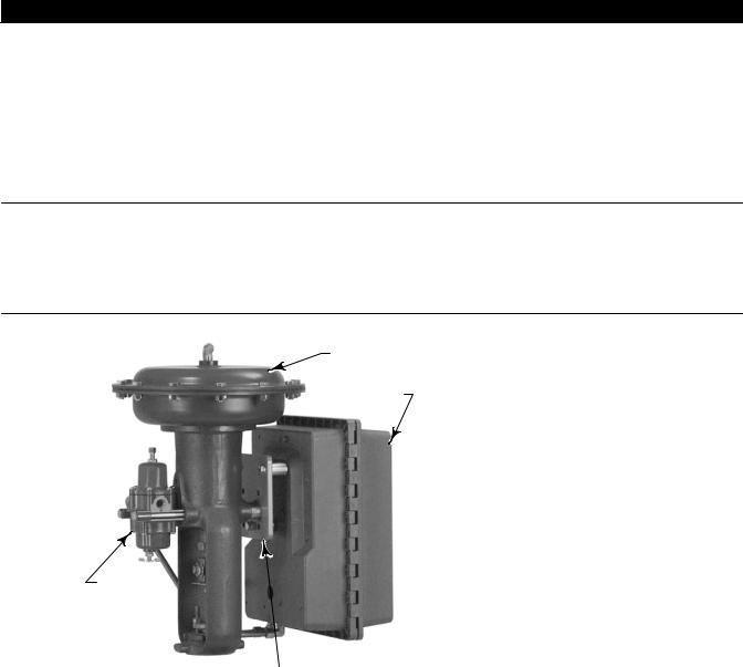
Mount the controller with the housing vertical, as shown in figure 2 1, so the vent points down.
Figure 2 1. Typical Actuator Mounting
FISHER 657 ACTUATOR
4195K CONTROLLER
67CFR FILTER REGULATOR
|
|
MOUNTING |
|
|
|
W8462-1 |
|
PLATE |
|
|
|
|
|
|
Pipestand Mounting
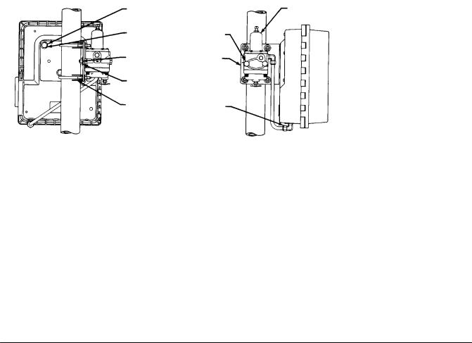
Refer to figure 2 2. Pipestand mounting parts are provided to mount the controller to a 2 inch (nominal) pipe. Attach a bracket (key 68) to the controller with cap screws (key 66) and lock washers (key 67). Attach two clamps (key 69) to the bracket and fasten the controller to the pipe.
9
4195K Controllers |
Instruction Manual |
|
December 2012 |
D200160X012 |
|
|
|
|
|
|
|
Figure 2 2. Pipestand Mounting |
|
|
HEX HEAD |
|
|
CAP SCREW |
REGULATOR |
|
(KEY 66) |
HEX HEAD |
|
|
||
LOCKWASHER |
CAP SCREW |
|
(KEY 362) |
||
(KEY 67) |
||
|
||
HEX NUT |
BRACKET |
|
(KEY 68) |
||
(KEY 364) |
||
|
||
LOCKWASHER |
|
|
(KEY 363) |
|
|
PIPE CLAMP |
ELBOW |
|
(KEY 69) |
||
(KEY 365) |
||
|
49A3196 A
A6732
VERTICAL PIPE
|
HEX HEAD |
|
|
CAP SCREW |
|
|
(KEY 362) |
|
LOCKWASHER |
PIPE CLAMP |
|
(KEY 363) |
||
(KEY 69) |
||
|
||
HEX NUT |
|
|
(KEY 364) |
|
|
HEX HEAD |
BRACKET |
|
CAP SCREW |
(KEY 68) |
|
(KEY 66) |
|
|
LOCKWASHER |
ELBOW |
|
(KEY 365) |
||
(KEY 67) |
||
|
HORIZONTAL PIPE
Panel Mounting
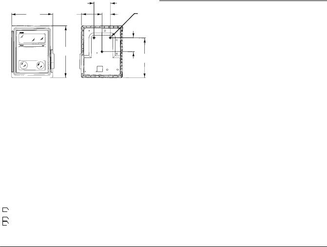
Using the dimensions shown in figure 2 3, cut a hole in the panel surface. Slide the controller into the hole and attach the bracket (key 68) to the rear of the controller using three cap screws (key 66) and lock washers (key 67). Tighten the screws (key 70) to seat the case snugly and evenly against the panel surface.
10
Instruction Manual |
|
4195K Controllers |
D200160X012 |
|
December 2012 |
|
|
|
|
|
|
Figure 2 3. Panel Mounting |
HEX HEAD |
|
|
13 |
|
|
CAP SCREW |
|
|
(0.50) |
|
|
(KEY 66) |
|
|
|
|
|
BRACKET |
62 |
|
(KEY 68) |
(2.43) |
|
ROUND |
|
|
HEAD |
306 |
LOCK |
MACHINE |
(12.06) |
SCREW |
|
|
WASHER |
|
|
(KEY 70) |
14 |
(KEY 67) |
TOP VIEW |
|
(0.56 R) |
|
|
||
|
|
|
|
|
|
|
236 |
|
|
REAR VIEW |
(9.31) |
|
|
|
36A9760 A
A6733
mm
DIMENSIONS OF (INCH) PANEL CUTOUT
Wall Mounting
Using the dimensions in figure 2 4, drill holes in the wall to align with the four holes in the bracket (key 68). If the tubing is to run through the wall, drill a hole in the wall large enough to accept the tubing. Mount the controller to the bracket using three cap screws (key 66) and lock washers (key 67). Attach the bracket to the wall, using suitable screws or bolts.
Figure 2 4. Wall Mounting
HEX HEAD CAP SCREW (KEY 66)
161
(6.35)
36A9761 B
A6734
TOP VIEW |
LOCKWASHER |
|
|
|
(KEY 67) |
(0
|
BRACKET |
|
(KEY 68) |
REAR VIEW |
mm |
|
(INCH) |
Actuator Mounting
Refer to figure 2 1. A controller specified for mounting on a control valve actuator is mounted at the factory. If the controller is ordered separately for installation on a control valve actuator, mount the unit as described in this section. Mounting parts vary for different actuator types.
Attach the mounting bracket to the actuator yoke with cap screws, lock washers, and spacer spools. Attach the controller to the bracket with cap screws, lock washers, and spacer spools. On some designs, the mounting bracket is attached to the actuator casing rather than to the yoke.
11

4195K Controllers |
Instruction Manual |
December 2012 |
D200160X012 |
|
|
Pressure Connections

 WARNING
To avoid personal injury or property damage resulting from the sudden release of pressure, do not install any system component where service conditions could exceed the limits given in this manual. Use pressure relieving devices as required by government or accepted industry codes and good engineering practices.
Refer to figure 2 5 for pressure connection locations. Supply, output, remote set point, external feedback, and vent connections are 1/4 NPT, internal. Process pressure connections are 1/4 or 1/2 NPT (optional). Use 1/4 inch or 3/8 inch pipe or tubing for supply, output, remote set point, and external feedback connections.
Process Pressure Connection
The connection marked A on the bottom of the case is the process input for all Bourdon tube controllers and those capsular element controllers used in vacuum pressure applications. The connection marked B is the process input for capsular element controllers used in positive pressure and compound pressure applications. See figure 2 5 for the location of the A and B connections.
When installing process piping, follow accepted practices to ensure accurate transmission of the process pressure to the controller. Install a three valve bypass, shutoff valves, vents, drains, or seal systems as needed in the process pressure lines. If necessary, install a needle valve in a process pressure sensing line to dampen pulsations.
If the instrument is located such that the adjacent process pressure lines are approximately horizontal, the lines should slope downward to the instrument for liquid filled lines and upward toward the instrument for gas filled lines. This reduces the possibility of air becoming trapped in the sensor with liquid filled lines or of condensation becoming trapped in gas filled lines. The recommended slope is 83 millimeters per m (1 inch per foot).
If the controller is being used in conjunction with a control valve to control pipeline pressure, connect the process pressure line in a straight section of pipe approximately 10 pipe diameters away from the valve and also away from bends, elbows, and areas of abnormal fluid velocities. For pressure reducing service, the process pressure line must be connected downstream of the control valve. For pressure relief service, the process pressure line must be connected upstream of the control valve.
Supply Pressure Connection

 WARNING
Severe personal injury or property damage may occur if the instrument air supply is not clean, dry and oil free, or noncorrosive gas. While use and regular maintenance of a filter that removes particles larger than 40 micrometers in diameter will suffice in most applications, check with an Emerson Process Management field office and industry instrument air quality standards for use with corrosive gas or if you are unsure about the proper amount or method of air filtration or filter maintenance.
Supply pressure must be clean, dry air or noncorrosive gas that meets the requirements of ISA 7.0.01. A maximum 40 micrometer particle size in the air system is acceptable. Further filtration down to 5 micrometer particle size is recommended. Lubricant content is not to exceed 1 ppm weight (w/w) or volume (v/v) basis. Condensation in the air supply should be minimized. Natural gas must be clean, dry, oil free, and noncorrosive. H2S content should not exceed 20 ppm.
12
Instruction Manual |
4195K Controllers |
D200160X012 |
December 2012 |
|
|
Use a suitable supply pressure regulator to reduce the supply pressure source to the normal operating supply pressure shown in table 1-6. Connect supply pressure to the SUPPLY connection on the bottom of the case, shown in figure 2 5.
Remote Set Point (suffix letter M) Pressure Connection
If the controller has remote set point (suffix letter M), connect the remote set point pressure to the top of the controller case at the location shown in figure 2 5. Use clean, dry air or noncorrosive gas. Use a 0.2 to 1.0 bar (3 to 15 psig) remote set point pressure range for a 0.2 to 1.0 bar (3 to 15 psig) controller output signal range or a 0.4 to 2.0 bar (6 to 30 psig) remote set point pressure range for a 0.4 to 2.0 bar (6 to 30 psig) controller output signal range. If pressure is supplied to the remote set point connection with a regulator, a small bleed orifice should be placed between the regulator and remote set point connection to prevent pressure variations due to regulator lock up.
External Feedback Pressure Connection (4195KB Controllers Only)
When a secondary controller in an override application has this option, reset windup is minimized in the secondary controller. Connect the external feedback connection of the secondary controller to the output of the customer supplied high or low select relay (see figures 2 5 and 4 9).
Figure 2 5. Connection Locations
FRONT VIEW |
|
REAR VIEW |
|
1/4 18 NPT CONTROLLER |
1/4 18 NPT |
||
SUPPLY PRESSURE |
|||
OUTPUT CONNECTION |
|||
CONNECTION |
|||
|
|||
|
|
147 |
|
|
66 |
(5.80) |
|
|
(2.56) |
|
|
|
31 |
1/4 NPT |
|
1/4 18 |
(1.22) |
REMOTE SET POINT CONNECTION |
|
|
|
||
NPT VENT
CONNECTION 1/4 NPT 4 HOLES
BOTTOM VIEW |
TOP VIEW |
|
NOTES:
1Ã1/4 18 NPT PROCESS CONNECTION (MARKED A) FOR ALL BOURDON TUBE CONTROLLERS AND FOR THOSE CAPSULAR ELEMENT CONTROLLERS USED IN VACUUM PRESSURE APPLICATIONS.
2Ã1/4 18 NPT PROCESS CONNECTION (MARKED B) FOR CAPSULAR ELEMENT CONTROLLERS USED IN POSITIVE AND COMPOUND PRESSURE APPLICATIONS. 3ÃFOR THE EXTERNAL FEEDBACK CONNECTIONS (4195KB CONTROLLERS ONLY), EITHER THE A OR B CONNECTION IS USED, DEPENDING ON THE LOCATION OF THE PROCESS CONNECTION.
46A9765 A
A2892 4
mm (INCH)
13

4195K Controllers |
Instruction Manual |
December 2012 |
D200160X012 |
|
|
Vent

 WARNING
Personal injury or property damage could result from fire or explosion of accumulated gas, or from contact with hazardous gas, if a flammable or hazardous gas is used as the supply pressure medium. Because the controller case and cover assembly do not form a gas tight seal when the assembly is enclosed, a remote vent line, adequate ventilation, and necessary safety measures should be used to prevent the accumulation of flammable or hazardous gas. However, a remote vent pipe alone cannot be relied upon to remove all flammable or hazardous gas. Vent line piping should comply with local and regional codes and should be as short as possible with adequate inside diameter and few bends to reduce case pressure buildup.
CAUTION
When installing a remote vent pipe, take care not to over tighten the pipe in the vent connection. Excessive torque will damage the threads in the connection.
If a remote vent is required, the vent line must be as short as possible with a minimum number of bends and elbows. Vent line piping should have a minimum inside diameter of 19 mm (3/4 inches) for runs up to 6.1 meters (20 feet) and a minimum inside diameter of 25 mm (1 inch) for runs from 6.1 to 30.5 meters (20 to 100 feet).
The vent must be protected against the entrance of any foreign material that could plug it; or if a remote vent is not required, the vent opening in the case must be protected against the entrance of any foreign material that could plug it. Check the vent periodically to be certain it is not plugged.
14
Instruction Manual |
4195K Controllers |
D200160X012 |
December 2012 |
|
|
Section 3 4195KA Proportional Only Controllers
Adjustments for 4195KA Controllers
This section includes descriptions of adjustments and procedures for prestartup, startup, and calibration. Adjustment locations are shown in figures 3 1 and 3 3. To better understand the adjustments and overall controller operation, refer to the Principle of Operation section and the schematic diagrams in figures 3 4 and 3 5. Unless otherwise noted, key numbers given in this section are found in figure 7 1.
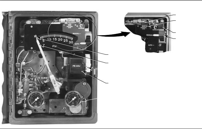
Figure 3 1. Fisher 4195KA Controller Adjustment Locations
|
METAL BALL |
|
SWITCHING |
|
ZONE |
|
INDICATOR |
|
LOADER KNOB |
|
AUTO/MANUAL |
|
SWITCH |
W3679 |
|
SET POINT |
|
INDICATOR |
AUTO/MANUAL STATION |
PROCESS POINTER |
(SUFFIX LETTER E) |
 PROPORTIONAL BAND
ADJUSTMENT
PROPORTIONAL BAND
INDICATOR COVER
 OUTPUT PRESSURE GAUGE
W6832
Manual Set Point Adjustment
Adjust the set point by moving the set point indicator until the line on the set point indicator is over the desired value on the process pressure scale. Move the indicator to the right to increase the set point and to the left to decrease it. Adjusting the set point does not affect the proportional band setting.
15
4195K Controllers |
Instruction Manual |
December 2012 |
D200160X012 |
|
|
Remote Set Point (suffix letter M) Adjustment
CAUTION
Do not manually move the set point indicator on controllers with remote set point. Manually moving the set point indicator could damage the controller.
If the controller is equipped with remote set point (suffix letter M), vary the remote set point pressure to change the set point. Increase the pressure to increase the set point, and decrease the pressure to decrease the set point.
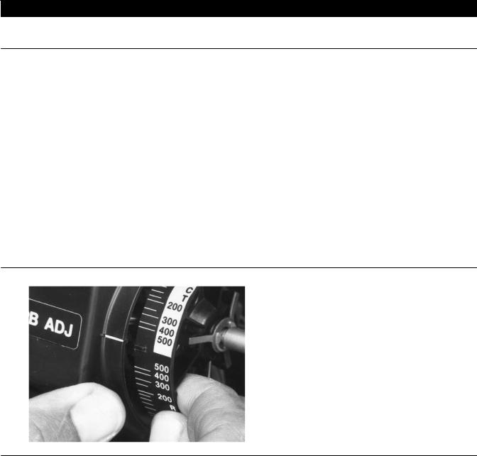
Proportional Band Adjustment (PB ADJ)
The proportional band determines the controller output sensitivity. The proportional band adjustment is marked in percentages of process pressure required to drive the controller from zero output to full output.
To adjust the proportional band, open the controller cover and locate the proportional band adjustment (PB ADJ) knob. Rotate the knob until the desired value is opposite the line on the proportional band indicator cover.
Changing Controller Action
To change the controller action from direct to reverse or vice versa, loosen the screws on the proportional band indicator cover. Lift the cover out as shown in figure 3 2 and rotate the proportional band adjustment to the desired action. Setting the proportional band to the values in the white portion of the adjustment provides direct controller action; setting proportional band in the black portion provides reverse controller action.
Figure 3 2. Changing Controller Action on Fisher 4195KA Controllers
W3439
Bourdon Tube or Capsular Element Controllers for Positive or Compound Pressure
D For direct control action—An increasing sensed pressure increases output pressure.
D For reverse control action—An increasing sensed pressure decreases output pressure.
Capsular Element Controllers for Vacuum Pressure
D For direct control action—An increasing sensed vacuum increases output pressure.
16

Instruction Manual |
4195K Controllers |
D200160X012 |
December 2012 |
|
|
D For reverse control action—An increasing sensed vacuum decreases output pressure.
After changing the action, tighten the screws on the proportional band indicator cover.
Switching The Auto/Manual Station (suffix letter E)
Note
Switching the controller between automatic and manual, or manual and automatic mode, without balancing the outputs, can disturb the process and cause controller cycling.
Refer to figure 3 1 if the controller has the auto/manual station (suffix letter E). To switch from automatic to manual mode, or from manual to automatic, you must first balance the manual output with the controller output. Two balance methods are available to equalize the manual output with the controller output.
To switch from automatic to manual mode, carefully adjust the loader knob until the metal ball inside the plastic tube moves into the switching zone. Then move the automatic/manual switch to MANUAL. Turn the loader knob clockwise to increase the controller output or counterclockwise to decrease it.
To switch from manual to automatic mode, adjust the set point to move the ball into the switching zone. Turn the switch to AUTO and adjust the set point to control the output.
When the auto/manual switch is in AUTO, adjusting the loader knob has no effect on the controller output. When the auto/manual switch is in MANUAL, changing the set point has no effect on the controller output.
Prestartup Checks for 4195KA Controllers
Refer to figure 3 1 for adjustment locations and refer to figure 7 1 for key number locations.
When performing the checks, open loop conditions must exist. An open loop exists when the controller output does not affect the input pressure or other control signal to the controller.
Note
If the controller has the auto/manual station (suffix letter E), be sure the controller is in the automatic mode before performing the prestartup checks.
1.Provide a means of measuring the controller output pressure by connecting the controller output to a pressure gauge. Connect supply pressure to the supply pressure regulator and be sure it is delivering the proper supply pressure to the controller. Do not exceed the normal operating pressure in table 1-6.
2.For a controller with remote set point (suffix letter M), connect regulated pressure of 0.2 to 1.0 bar (3 to 15 psig) or 0.4 to 2.1 bar (6 to 30 psig) to the remote set point connection at the top of the controller case.
3.Remove the two machine screws (key 6) and lift off the proportional band indicator cover (key 36).
4.Adjust the set point a minimum of 20 percent of input span above the process pointer.
5.Adjust the proportional band for 5 percent DIRECT.
6.If necessary, connect a pressure source to the process connection and adjust the process pointer to the last mark on the left side of the scale. If the last scale mark is 0 psig, a pressure source is not required.
17

4195K Controllers |
Instruction Manual |
December 2012 |
D200160X012 |
|
|
7.The controller output pressure should be 0 bar (0 psig).
8.Rotate the proportional band to 5 percent REVERSE.
9.The controller output should be within 0.14 bar (2 psig) of the supply pressure.
10.If the controller output is within tolerance, adjust the proportional band to 400 percent in the desired action, secure the proportional band indicator cover (key 36) with the machine screws (key 6), and go to the startup procedure. If the controller output pressure is not within tolerance, go to the 4195KA calibration procedure for recalibration.
Startup for 4195KA Controllers
Perform the prestartup checks and, if necessary, calibrate the controller prior to this procedure.
Note
When performing the startup procedures, keep in mind that the initial settings are guidelines. They will vary depending on the actual process being controlled.
1.Be sure the supply pressure regulator is delivering the proper supply pressure to the controller.
2.For controllers with:
Manual set point:
Move the set point adjustment to the desired set point.
Remote set point:
a.See figure 2 5 for the location of the remote set point connection. Connect an adjustable pressure source to the remote set point connection.
b.Adjust the pressure source until the set point indicator reaches the desired set point. Remember: Increasing the remote set point pressure increases the set point.
3.Set the proportional band adjustment to 100 percent for fast processes. For slow processes, calculate the proportional band percentage from the equation below:
P.B. + |
200 Allowable Overshoot |
|
|
||
Pressure Span |
||
|
For example:
200 0.14 bar |
^ 13% |
|
|
||
2.1 bar |
||
|
4.Create a load upset by momentarily changing the set point. Check for system cycling. If the system does not cycle, lower the proportional band setting (thus raising the gain) and disturb the system again by changing the set point. Continue this procedure until the system cycles. At this point, double the proportional band setting (proportional band setting x2).
5.Check the stability of the recommended proportional band setting by introducing a disturbance and monitoring the process.
Calibration of 4195KA Controllers

 WARNING
To avoid personal injury or property damage resulting from the sudden release of pressure, do not exceed the operating limits given in this manual.
18

Instruction Manual |
4195K Controllers |
D200160X012 |
December 2012 |
|
|
General Calibration Instructions
Note
If the controller has the auto/manual station (suffix letter E), be sure the controller is in the automatic mode before performing calibration.
If the prestartup checks, or startup, reveal faulty controller operation, perform the calibration described in this section. These instructions are valid for either shop or field calibration, provided that open process loop conditions exist. Unless otherwise noted, key numbers are found in figure 7 1.
Do not use the gauges supplied with the controller during calibration. Monitor process pressure, supply pressure, controller output pressure, and if applicable, remote set point pressure with external gauges.
Process Indicator Zero and Span Calibration
Before starting this procedure:
D Provide a regulated process pressure to the controller and a means of measurement external to the controller.
D Provide a means of measuring the controller output pressure by connecting the controller output to a pressure gauge (open loop conditions must exist). Provide a regulated supply pressure to the controller. Do not exceed the normal operating pressure in table 1-6.
Refer to figures 3 1 and 3 3 for adjustment locations.
Note
Any change to the process pointer span adjustment will require readjustment of the process pointer zero adjustment.
19

4195K Controllers |
Instruction Manual |
December 2012 |
D200160X012 |
|
|
Figure 3 3. Fisher 4195KA Controller Calibration Adjustment Locations
 POINTER ZERO
ADJUSTMENT
POINTER ZERO
ADJUSTMENT LOCKING SCREW
REMOTE SET POINT
ZERO ADJUSTMENT
(SUFFIX LETTER M)
W6832
REMOTE SET POINT |
PROCESS POINTER |
|
ZERO ADJUSTMENT |
||
SPAN ADJUSTMENT |
||
LOCKING SCREW |
||
|
||
(SUFFIX LETTER M) |
|
FRONT VIEW
SCREW 1
SCREW 2
SCREW 3
|
39A1126 B |
|
PROCESS |
REMOTE SET POINT |
|
POINTER SPAN |
SPAN ADJUSTMENT |
|
ADJUSTMENT |
(SUFFIX LETTER M) |
|
A6730 |
SIDE VIEW OF SET POINT/ |
|
|
PROCESS INDICATOR ASSEMBLY |
|
56A9752 S SHT 1
SIDE VIEW OF CONTROLLER
SHOWING FLAPPER LEVELING SCREWS
20
Instruction Manual |
4195K Controllers |
D200160X012 |
December 2012 |
|
|
1.Remove the two screws (key 6) and lift off the proportional band indicator cover (key 36).
2.Set the proportional band between DIRECT and REVERSE.
3.Apply process pressure equal to the process scale span lower limit.
4.The process pointer should indicate the process scale lower limit. If not, adjust the process pointer to the process scale lower limit by loosening the zero adjustment locking screw and turning the zero adjustment screw. Tighten the zero adjustment locking screw.
5.Apply process pressure equal to the process scale span upper limit.
6.The process pointer should indicate the process scale upper limit. If not, adjust the span screw to correct one half of the error as follows: clockwise to increase span for a low indication (below the upper limit); counterclockwise to decrease span for a high indication (above the upper limit).
7.Repeat steps 3 through 6 until the error is eliminated.
8.Apply process pressure equal to the mid scale value of the process scale span. The process pointer should indicate the mid scale mark, ±2 percent of span. If the error is greater than ±2 percent, refer to the Maintenance section and perform the appropriate zero and span adjustment procedure for a Bourdon tube or capsular element controller.
9.Adjust the process pointer to within ±1 percent of the mid scale mark by loosening the locking screw and turning the zero adjustment screw. This distributes the error over the entire scale span and brings all points within ±1 percent of the process input span.
10.Apply process pressure equal to the process scale span lower limit.
11.The process pointer should indicate the process scale lower limit ±1 percent of the scale span.
12.Apply process pressure equal to the process scale span upper limit.
13.The process pointer should indicate the process scale upper limit ±1 percent of the scale span.
14.If the error is greater than ±1 percent, repeat steps 3 through 13.
Remote Set Point (suffix letter M) Zero and Span Calibration
Refer to figures 3 1 and 3 3 for adjustment locations. Refer to figure 7 1 for key number locations.
Note
Any adjustment of the remote set point span adjustment screw requires readjustment of the remote set point zero adjustment screw.
1.Remove the two screws (key 6) and lift off the proportional band indicator cover (key 36).
2.Set the proportional band between DIRECT and REVERSE.
3.Apply remote set point pressure equal to the lower range limit.
4.The set point indicator should indicate the process scale lower limit. If not, loosen the remote set point zero adjustment locking screw and adjust the remote set point zero adjustment screw until the set point indicator aligns with the process scale lower limit. Tighten the zero adjustment locking screw.
5.Apply remote set point pressure equal to the upper range limit.
6.The set point indicator should indicate the process scale upper limit. If not, adjust the remote set point span adjustment screw to correct one half the error as follows: clockwise to increase span for a low indication; counterclockwise to decrease span for a high indication.
7.Repeat steps 3 through 6 until the error is eliminated.
8.Apply remote set point pressure equal to the mid range value.
21

4195K Controllers |
Instruction Manual |
December 2012 |
D200160X012 |
|
|
9.Make sure the set point indicator is within ±1 percent of the mid scale mark and if so, proceed to step 12. If the set point indicator is not within 1 percent, but is within ±2 percent of the mid scale mark, then proceed with step 10. If the set point indicator is not within ±2 percent, proceed to the remote set point calibration procedure in the Maintenance section.
10.Loosen the remote set point zero adjustment locking screw and adjust the remote set point zero adjustment screw to correct for half the error at mid scale. Tighten the zero adjustment locking screw.
11.Apply remote set point pressure equal to the lower and upper range limits and make sure the set point indicator is within ±1 percent.
12.If necessary, perform the process indicator zero and span calibration procedure in this section. Otherwise, perform the flapper alignment procedure in this section.
Flapper Alignment
Note
Perform the process indicator zero and span calibration procedure and, for controllers with remote set point (suffix letter M), the remote set point zero and span calibration procedure before the flapper alignment.
Flapper leveling screw numbers and adjustments are shown in figure 3 3. Key number locations are shown in figure 7 1.
Provide a means of measuring the controller output pressure by connecting the controller output to a pressure gauge (open loop conditions must exist). Provide a regulated supply pressure to the controller. Do not exceed the normal operating pressure in table 1-6. After performing the flapper alignment procedure, go to the startup procedure.
1.For a controller with manual set point, move the set point indicator to the mid scale mark on the process scale. For a controller with remote set point (suffix letter M), adjust the remote set point pressure until the set point indicator is at the mid scale mark on the process scale.
2.Apply process pressure equal to the mid scale value of the process scale span. If pressure is not available to pressure the input element to the mid scale value, an alternate method is to disconnect link number 1 at the input element and tape the process pointer at the mid scale mark on the process scale. If the controller has a capsular input element, note the hole from which link number 1 was removed for proper replacement. This method should only be used if pressure is not available to pressure the input element to the mid scale value.
3.Remove the two machine screws (key 6) and lift off the proportional band indicator cover (key 36).
4.Adjust the proportional band between DIRECT and REVERSE.
5.The controller output should be 0.62 ±0.007 bar (9 ±0.10 psig) for a 0.2 to 1.0 bar (3 to 15 psig) output or 1.2 ±0.01 bar (18 ±0.2 psig) for a 0.4 to 2.0 bar (6 to 30 psig) output. If not, adjust flapper leveling screw 2 (the screw nearest the nozzle) until the output is within tolerance.
6.Set the proportional band to 30 percent DIRECT.
7.The controller output should be 0.62 ±0.02 bar (9 ±0.25 psig) or 1.2 ±0.04 bar (18 ±0.5 psig). If not, adjust flapper leveling screw 3 (the screw nearest the nozzle).
8.Set the proportional band to 30 percent REVERSE.
9.The controller output should be 0.62 ±0.02 bar (9 ±0.25 psig) or 1.2 ±0.04 bar (18 ±0.5 psig). If not, adjust flapper leveling screw 1 (the screw nearest the nozzle).
10.Repeat steps 4 through 9 until the controller output remains in tolerance without further leveling screw adjustments.
11.If link 1 was disconnected, remove the tape and reconnect link 1 to the input element.
22
Instruction Manual |
4195K Controllers |
D200160X012 |
December 2012 |
|
|
12.Set the proportional band to 400 percent in the desired controller action and replace the proportional band indicator cover.
Principle of Operation for 4195KA Controllers
Overall Operation
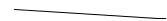
Refer to the schematic diagram in figure 3 4.
Figure 3 4. Fisher 4195KA Controller Schematic
SET POINT INDICATOR |
RESET BELLOWS (VENTED) |
|
REVERSE ACTION |
|
PROPORTIONAL |
PROPORTIONAL |
QUADRANT |
|
|
||
|
BELLOWS |
|
|
|
BAND ADJUSTMENT |
|
|
|
|
|
|
|
|
FEEDBACK |
|
PROCESS POINTER |
|
LINK |
|
REMOTE SET POINT |
|
|
|
CONNECTED HERE |
|
FEEDBACK |
|
|
|
|
|
INPUT ELEMENT |
|
MOTION |
FLAPPER PIVOT |
CONNECTED HERE |
|
|
|
|
|
DIRECT ACTION |
INPUT |
CONNECTING |
|
QUADRANT |
|
|
MOTION |
||
LINK
FLAPPER DETAIL
BEAM
|
OUTPUT PRESSURE |
|
|
TO FINAL CONTROL |
|
|
ELEMENT |
|
|
FLAPPER |
|
SUPPLY PRESSURE |
NOZZLE |
|
RELAY |
||
|
||
OUTPUT PRESSURE |
|
|
PROPORTIONAL PRESSURE |
SUPPLY |
|
PRESSURE |
||
|
||
NOZZLE PRESSURE |
|
|
46A9764 A |
|
|
B1489 2 |
|
|
|
|
The input element is connected to the process pointer and to the flapper by connecting links. As the process pressure increases (in a direct acting controller), the flapper moves toward the nozzle, restricting flow through the nozzle and increasing nozzle pressure. When this occurs, relay action increases the output pressure (delivery) of the controller.
Output pressure is fed back to the proportional bellows. The action of the proportional bellows counteracts the flapper movement that resulted from the process pressure change and backs the flapper away from the nozzle until equilibrium is reached.
Moving the set point indicator changes the distance between the nozzle and flapper as does a change in process pressure, except that when the set point is changed, the nozzle moves with respect to the flapper.
The proportional band adjustment positions the nozzle on the flapper. Increasing (widening) the proportional band moves the nozzle to a position on the flapper where less input and more feedback motion occurs, which decreases the gain of the controller. Decreasing (narrowing) the proportional band moves the nozzle toward a position where more input and less feedback motion occurs, which increases the gain. The controller action is changed from direct to reverse by turning the proportional band adjustment to position the nozzle on the flapper quadrant to a point where the direction of the flapper motion versus input motion is reversed as shown in the flapper detail of figure 3 4. With the controller in the reverse acting mode, an increase in process pressure causes a decrease in output pressure.
23
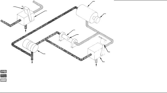
4195K Controllers |
Instruction Manual |
December 2012 |
D200160X012 |
|
|
Remote Set Point (suffix letter M) Operation
The capability to adjust the controller set point from a remote location is available with all 4195KA controllers. This option is designated by the letter M in the type number.
A control pressure is applied to the capsular element within the remote set point assembly. The expansion and contraction of the capsule moves the set point adjustment via a connecting linkage. Increasing the control pressure to the capsule increases the set point setting and decreasing the control pressure reduces the set point setting.
Auto/Manual Station (suffix letter E) Operation
A controller with the auto/manual station (designated by the suffix letter E in the type number) has piping on the output side of the relay as shown in figure 3 5. Supply pressure to the relay is also applied to the manual loader. The manual loader, functioning as a regulator, applies pressure to one side of the plastic tube and to the auto/manual switch. Output pressure from the relay registers on the other side of the plastic tube as well as in the auto/manual switch.
Figure 3 5. Fisher 4195KA Auto/Manual Station Schematic
48A5230 A
A2999 1
|
MANUAL LOADER |
|
AUTOMATIC |
|
|
POSITION |
AUTO/MANUAL |
|
|
||
|
SWITCH |
|
|
MANUAL |
|
|
LOADER KNOB |
|
|
PLASTIC |
|
OUTPUT PRESSURE |
TUBE |
|
|
||
TO FINAL CONTROL |
METAL |
|
ELEMENT |
BALL |
|
|
MANUAL POSITION |
|
|
RELAY |
|
|
AUTO/MANUAL |
|
SUPPLY PRESSURE |
SWITCH |
|
|
||
RELAY OUTPUT PRESSURE |
OUTPUT PRESSURE |
|
TO FINAL CONTROL |
||
|
||
SUPPLY PRESSURE |
ELEMENT |
MANUAL LOADER OUTPUT PRESSURE
When the auto/manual switch is in the MANUAL position, the manual loader output is channeled through the auto/manual switch and becomes the controller output. When the auto/manual switch is in the AUTO position, the relay output is channeled through the switch to become the controller output.
Before the auto/manual switch is operated, the relay output must equal the manual loader output to avoid bumping the process. Adjusting the set point varies the pressure on the left hand side of the plastic tube. Adjusting the manual loader knob varies the pressure on the right hand side. When the pressures are equal, the metal ball is centered in the tube and it is held in place by a small magnet. A pressure imbalance forces the ball to one end of the tube where it forms a seal, blocking air flow through the tube.
24
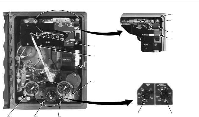
Instruction Manual |
4195K Controllers |
D200160X012 |
December 2012 |
|
|
Section 4 4195KB Proportional Plus Reset Controllers and
4195KC Proportional Plus Reset Plus Rate Controllers
Adjustments for 4195KB and KC Controllers
This section includes descriptions of adjustments and procedures for prestartup, startup, and calibration. Adjustment locations are shown in figures 4 1 and 4 3. To better understand the adjustments and overall controller operation, refer to the Principle of Operation section and to the schematic diagrams in figures 4 5 through 4 9. Unless otherwise noted, key numbers given in this section are found in figure 7 1.
Figure 4 1. Fisher 4195KB and KC Controller Adjustment Locations
|
METAL BALL |
|
SWITCHING |
|
ZONE |
|
INDICATOR |
|
LOADER KNOB |
|
AUTO/MANUAL |
|
SWITCH |
SET POINT |
|
INDICATOR |
W3679 |
|
|
PROCESS POINTER |
AUTO/MANUAL STATION |
|
(SUFFIX LETTER E) |
 PROPORTIONAL BAND
ADJUSTMENT
ANTI RESET WINDUP
DIFFERENTIAL RELIEF
VALVE (SUFFIX LETTER F)
SUPPLY |
RESET |
|
RATE |
|
|
|
RESET |
|
|
|
|
||||
OUTPUT PRESSURE GAUGE |
ADJUSTMENT |
|
ADJUSTMENT |
||||
PRESSURE GAUGE ADJUSTMENT |
|
|
|
|
|
|
|
|
|
|
W3599-1 |
|
|
||
|
TYPICAL ADJUSTMENTS |
|
4195KC RESET AND RATE ADJUSTMENTS |
||||
W6833 |
4195KB SHOWN |
|
|
|
|
|
|
|
|
|
|
|
|
|
|
Manual Set Point Adjustment
Adjust the set point by opening the controller cover and moving the set point indicator until the line on the set point indicator is over the desired value on the process pressure scale. Move the indicator to the right to increase the set point and to the left to decrease it. Adjusting the set point does not affect the proportional band setting.
25
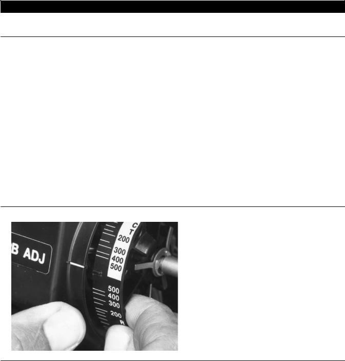
4195K Controllers |
Instruction Manual |
December 2012 |
D200160X012 |
|
|
Remote Set Point (suffix letter M) Adjustment
CAUTION
Do not manually move the set point indicator on a controller with remote set point. Manually moving the set point indicator could damage the controller.
If the controller is equipped with remote set point (suffix letter M), vary the remote set point pressure to change the set point. Increase the pressure to increase the set point and decrease the pressure to decrease the set point.
Proportional Band Adjustment (PB ADJ)
The proportional band determines the controller output sensitivity. The proportional band adjustment is marked in percentages of process pressure required to drive the controller from zero output to full output.
To adjust the proportional band, open the controller cover and locate the proportional band adjustment (PB ADJ) knob. Rotate the knob until the desired value is opposite the line on the proportional band indicator cover.
Changing Controller Action
To change the controller action from direct to reverse or vice versa, loosen the screws on the proportional band indicator cover. Lift the cover out as shown in figure 4 2 and rotate the proportional band adjustment to the desired action. Setting the proportional band to the values in the white portion of the adjustment provides direct controller action; setting proportional band in the black portion provides reverse controller action.
Figure 4 2. Changing Controller Action on Fisher 4195KB and KC Controllers
W3439
26

Instruction Manual |
4195K Controllers |
D200160X012 |
December 2012 |
|
|
Bourdon Tube or Capsular Element Controllers for Positive or Compound Pressure
D For direct control action— An increasing sensed pressure increases output pressure.
D For reverse control action— An increasing sensed pressure decreases output pressure.
Capsular Element Controllers for Vacuum Pressure
D For direct control action— An increasing sensed vacuum increases output pressure.
D For reverse control action— An increasing sensed vacuum decreases output pressure.
After changing the action, tighten the screws on the proportional band indicator cover.
Reset Adjustment
To adjust reset, open the controller cover and locate the RESET adjustment. Rotate the adjustment clockwise to decrease the minutes per repeat or counterclockwise to increase the minutes per repeat. Increasing the minutes per repeat provides a slower reset action.
Rate Adjustment
To adjust rate, open the controller cover and locate the RATE adjustment. Rotate the adjustment clockwise to decrease the minutes (less rate action) or counterclockwise to increase the minutes (more rate action).
Anti Reset Windup (suffix letter F) Adjustment
If the arrow on the relief valve points toward the bottom of the controller case, as shown in figure 4 1, the valve opens with increasing controller output pressure. If the arrow points in the opposite direction, the relief valve opens with decreasing controller output pressure. Differential relief pressure is factory set at 0.3 bar (5 psig). Maximum relief pressure is 0.5 bar (7 psig). The minimum is 0.1 bar (2 psig).
Turn the adjusting screw counterclockwise to increase differential relief pressure, clockwise to decrease it.
Switching the Auto/Manual Station (suffix letter E)
Note
Switching the controller between automatic and manual, or manual and automatic mode, without balancing the outputs, can disturb the process and cause controller cycling.
Refer to figure 4 1 if the controller has the auto/manual station (suffix letter E). To switch from automatic to manual mode, or from manual to automatic, you must first balance the manual output with the controller output. Two balance methods are available to equalize the manual output with the controller output.
To switch from automatic to manual mode, carefully adjust the loader knob until the metal ball inside the plastic tube moves into the switching zone. Then move the automatic/manual switch to MANUAL. Turn the loader knob clockwise to increase the controller output or counterclockwise to decrease it.
27

4195K Controllers |
Instruction Manual |
December 2012 |
D200160X012 |
|
|
To switch from manual to automatic mode, adjust the set point to move the ball into the switching zone. Turn the switch to AUTO and adjust the set point to control the output.
When the automatic/manual switch is in AUTO, adjusting the loader knob has no effect on the controller output. When the automatic/manual switch is in MANUAL, changing the set point has no effect on the controller output.
Prestartup Checks for 4195KB and KC Controllers
Refer to figure 4 1 for adjustment locations, and refer to figure 7 1 for key number locations.
When performing the checks, open loop conditions must exist. An open loop exists when the controller output does not affect the input pressure or other control signal to the controller.
Note
If the controller has the auto/manual station (suffix letter E), be sure the controller is in the automatic mode before performing prestartup checks. If the controller has the external feedback option, connect the controller output connection to the external feedback connection (see figure 2 5). Adjust the controller for full output pressure and with the RESET knob adjusted to 0.01 minutes/repeat, verify the tubing connections do not leak. Disconnect after completing the prestartup checks.
1.Provide a means of measuring the controller output pressure by connecting the controller output to a pressure gauge. Connect supply pressure to the supply pressure regulator and be sure it is delivering the proper supply pressure to the controller. Do not exceed the normal operating pressure in table 1-6.
2.For a controller with remote set point (suffix letter M), connect regulated pressure of 0.2 to 1.0 bar (3 to 15 psig) or 0.4 to 2.1 bar (6 to 30 psig) to the remote set point connection at the top of the controller case.
3.Remove the two machine screws (key 6) and lift off the proportional band indicator cover (key 36).
4.Adjust the set point a minimum of 20 percent of input span above the process pointer.
5.Turn the reset adjustment to 0.01 minutes per repeat.
6.Turn the rate adjustment to OFF (4195KC controllers).
7.Adjust the proportional band for 5 percent DIRECT.
8.If necessary, connect a pressure source to the process connection and adjust the process pointer to the last mark on the left side of the scale. If the last scale mark is 0 bar (0 psig), a pressure source is not required.
9.The controller output pressure should be 0 bar (0 psig).
10.Rotate the proportional band to 5 percent REVERSE.
11.The controller output should be within 0.14 bar (2 psig) of the supply pressure.
12.If the controller output is within tolerance, adjust the proportional band to 400 percent in the desired action. Secure the proportional band indicator cover (key 36) with the machine screws (key 6), and go to the startup procedure. If the controller output pressure is not within tolerance, go to the 4195KB and KC calibration procedure for recalibration.
Startup for 4195KB and KC Controllers
Perform the prestartup checks and, if necessary, calibrate the controller prior to this procedure.
Note
When performing the startup procedures, keep in mind that the initial settings are guidelines. They will vary depending on the actual process being controlled.
28
Instruction Manual |
4195K Controllers |
D200160X012 |
December 2012 |
|
|
1.Be sure the supply pressure regulator is delivering the proper supply pressure to the controller.
2.For controllers with:
Manual set point:
Move the set point indicator to the desired set point.
Remote set point:
a.See figure 2 5 for the location of the remote set point connection. Connect an adjustable pressure source to the remote set point connection.
b.Adjust the pressure source until the set point indicator reaches the desired set point. Remember: Increasing the remote set point pressure increases the set point.
3.Set the reset adjustment to 0.05 minutes per repeat for fast processes. Set it to 0.5 minutes per repeat for slow processes. For controllers with rate, set the rate adjustment to OFF.
4.Set the proportional band to 100 percent for fast processes. For slow processes, calculate the proportional band percentage from the equation below:
P.B. + |
200 Allowable Overshoot |
|
|
||
Pressure Span |
||
|
For example:
200 0.14 bar |
^ 13% |
|
|
||
2.1 bar |
||
|
5.If the controller is used in conjunction with a control valve, return the control valve to service by slowly opening the upstream and downstream manual control valves in the pipeline. Close the manual bypass valve, if one is used.
6.Tune the various controller actions.
Tuning proportional action: Create a load upset by momentarily changing the set point. Check for system cycling. If the system does not cycle, lower the proportional band setting (thus raising the gain) and disturb the system again by changing the set point. Continue this procedure until the system cycles. At this point, double the proportional band setting (proportional band setting ×2).
Tuning reset action: Disturb the system. If the system does not cycle, speed up the reset by changing the setting to a lower value (faster reset). Disturb the system again. Continue this procedure until the system cycles. When the system cycles, multiply the reset time setting by a factor of three (reset setting ×3) and slow down the reset by changing the reset setting to the higher value. The reset is now tuned.
Tuning rate action: For a controller with rate (4195KC controllers), adjust the rate toward the higher setting until cycling occurs. When the system cycles, divide the rate value by a factor of three (rate setting ÷3) and decrease the rate by changing the setting to the lower value. The rate is now tuned.
7.Check the stability of the recommended proportional band setting by introducing a disturbance and monitoring the process.
8.Once stable control is attained, the process pointer and set point indicator should be in line. If they are aligned, return the set point to the desired value. If they are not, readjust the set point to the desired control point and proceed with step 9.
9.If the process pointer is within 5 percent of the set point indicator, turn the link 3 adjustment (see figure 6 13
or 6 21 for location) until the process pointer aligns with the set point indicator. Turn the link 3 adjustment screw clockwise to increase the process indication or counterclockwise to decrease it. If the process pointer is misaligned with the set point indicator by more than 5 percent of the scale span, perform the calibration procedures for 4195KB and KC controllers.
29

4195K Controllers |
Instruction Manual |
December 2012 |
D200160X012 |
|
|
Calibration of 4195KB and KC Controllers

 WARNING
To avoid personal injury or property damage resulting from the sudden release of pressure, do not exceed the operating limits given in this manual.
General Calibration Instructions
Note
If the controller has the auto/manual station (suffix letter E), be sure the controller is in the automatic mode before performing calibration.
If the prestartup checks, or startup, reveal faulty controller operation, perform the calibration described in this section. These instructions are valid for either shop or field calibration, provided that open loop conditions exist. Unless otherwise noted, key numbers are found in figure 7 1.
Do not use the gauges supplied with the controller during calibration. Monitor process pressure, supply pressure, controller output pressure, and if applicable, remote set point pressure with external gauges.
Process Indicator Zero and Span Calibration
Before starting this procedure:
D Provide a regulated process pressure to the controller and a means of measurement external to the controller.
D Provide a means of measuring the controller output pressure by connecting the controller output to a pressure gauge (open loop conditions must exist). Provide a regulated supply pressure to the controller. Do not exceed the normal operating pressure in table 1-6.
Refer to figures 4 1 and 4 3 for adjustment locations.
Note
Any change to the process pointer span adjustment will require readjustment of the process pointer zero adjustment.
1.Remove the two screws (key 6) and lift off the proportional band indicator cover (key 36).
2.Set the proportional band between DIRECT and REVERSE.
3.Apply process pressure equal to the process scale span lower limit.
30
 Loading...