


 Loading...
HOME THEATER SYSTEM
DHT-M330DV
OPERATING INSTRUCTIONS
BEDIENUNGSANLEITUNG
MODE D’EMPLOI
ISTRUZIONI PER L’USO
INSTRUCCIONES DE OPERACION
GEBRUIKSAANWIJZING
BRUKSANVISNING
|
|
|
|
|
AVR-M330 |
|
|
|
|
|
|
|
|
|
|
|
DVD-M330 |
|
||||||||||||||
|
|
|
|
|
|
|
|
|
|
|
|
|
|
|
|
|
||||||||||||||||
|
|
|
|
|
|
|
|
|
|
|
|
|
|
|
|
|
|
|
|
|
|
|
|
|
|
|
|
|
|
|
|
|
|
|
|
|
|
|
|
|
|
|
|
|
|
|
|
|
|
|
|
|
|
|
|
|
|
|
|
|
|
|
|
|
|
|
|
|
|
|
|
|
|
|
|
|
|
|
|
|
|
|
|
|
|
|
|
|
|
|
|
|
|
|
|
|
|
|
|
|
|
|
|
|
|
|
|
|
|
|
|
|
|
|
|
|
|
|
|
|
|
|
|
|
|
|
|
|
|
|
|
|
|
|
|
|
|
|
|
|
|
|
|
|
|
|
|
|
|
|
|
|
|
|
|
|
|
|
|
|
|
|
|
|
|
|
|
|
|
|
|
|
|
|
|
|
|
|
|
|
|
|
|
|
|
|
|
|
|
|
|
|
|
|
|
|
|
|
|
|
|
|
|
|
|
|
|
|
|
|
|
|
|
|
|
|
|
|
|
|
|
|
|
|
|
|
|
|
|
|
|
|
|
|
|
|
|
|
|
|
|
|
|
|
|
|
|
|
|
|
|
|
|
|
|
|
|
|
|
|
|
|
|
|
|
|
|
|
|
|
|
|
|
|
|
|
|
|
|
|
|
|
|
|
|
|
|
|
|
|
|
|
|
|
|
|
|
|
|
|
|
|
|
|
|
|
|
|
|
|
|
|
|
|
|
|
|
|
|
|
|
|
|
|
|
|
|
|
|
|
|
|
|
|
|
|
|
|
|
|
|
|
|
|
|
|
|
|
|
|
|
|
|
|
|
|
|
|
|
|
|
|
|
|
|
|
|
|
|
|
|
|
|
|
|
|
|
|
|
|
|
|
|
|
|
|
|
|
|
|
|
|
|
|
|
|
|
|
|
|
|
|
|
|
|
|
|
|
|
|
|
|
|
|
|
|
|
|
|
|
|
|
|
|
|
|
|
|
|
|
|
|
|
|
|
|
|
|
|
|
|
|
|
|
|
|
|
|
|
|
|
|
|
|
|
|
|
|
|
|
|
|
|
|
|
|
|
|
|
|
|
|
|
|
|
|
|
|
|
|
|
|
|
|
|
|
|
|
|
|
|
|
|
|
|
|
|
|
|
|
|
|
|
|
|
|
|
|
|
|
|
|
|
|
|
|
|
|
|
|
|
|
|
|
|
|
|
SYS-M330 |
|
|
|
(SC-AM330) |
(SC-CM330) |
DSW-M330) |
(SC-AM330) |
• DVD-M330(DVD PLAYER): |
Please refer to the operating Instructions of the DVD-M330. |
|
• DVD-M330 |
(DVD-PLAYER): |
Bitte beziehen Sie sich auf die Bedienungsanleitung des DVD-M330. |
• DVD-M330 |
(LECTEUR DVD): |
Veuillez vous référer au mode d’emploi du DVD-M330. |
• DVD-M330 |
(LETTORE DVD): |
Fare riferimento al manuale delle istruzioni del modello DVD-M330. |
• DVD-M330 (REPRODUCTOR DVD): Consulte las instrucciones de funcionamiento del DVD-M330.
• DVD-M330 |
(DVD-SPELER): |
Zie de gebruiksaanwijzing van de DVD-M330. |
|||
• DVD-M330 |
(DVD-SPELARE): |
Läs bruksanvisningen till DVD-M330. |
|||
FOR ENGLISH READERS |
PAGE |
004 |
~ PAGE |
057 |
|
FÜR DEUTSCHE LESER |
SEITE |
058 |
~ SEITE |
111 |
|
POUR LES LECTEURS FRANCAIS |
PAGE |
112 |
~ PAGE |
165 |
|
PER IL LETTORE ITALIANO |
PAGINA |
166 |
~ PAGINA |
219 |
|
PARA LECTORES DE ESPAÑOL |
PAGINA |
220 |
~ PAGINA |
273 |
|
VOOR NEDERLANDSTALIGE LEZERS |
PAGINA |
274 |
~ PAGINA |
327 |
|
FOR SVENSKA LÄSARE |
SIDA |
328 |
~ SIDA |
381 |
|
ENGLISH DEUTSCH FRANCAIS ITALIANO ESPAÑOL NEDERLANDS SVENSKA
CAUTION
RISK OF ELECTRIC SHOCK
DO NOT OPEN
CAUTION: TO REDUCE THE RISK OF ELECTRIC SHOCK, DO NOT REMOVE COVER (OR BACK). NO USER SERVICEABLE PARTS INSIDE. REFER
SERVICING TO QUALIFIED SERVICE PERSONNEL.
The lightning flash with arrowhead symbol, within an equilateral triangle, is intended to alert the user to the presence of uninsulated “dangerous voltage” within the product’s enclosure that may be of sufficient magnitude to constitute a risk of electric shock to persons.
The exclamation point within an equilateral triangle is intended to alert the user to the presence of important operating and maintenance (servicing) instructions in the literature accompanying the appliance.
WARNING: TO REDUCE THE RISK OF FIRE OR ELECTRIC SHOCK, DO NOT EXPOSE THIS APPLIANCE TO RAIN OR MOISTURE.
•DECLARATION OF CONFORMITY
We declare under our sole responsibility that this product, to which this declaration relates, is in conformity with the following standards: EN60065, EN55013, EN55020, EN61000-3-2 and EN61000-3-3.
Following the provisions of 73/23/EEC, 89/336/EEC and 93/68/EEC Directive.
•ÜBEREINSTIMMUNGSERKLÄRUNG
Wir erklären unter unserer Verantwortung, daß dieses Produkt, auf das sich diese Erklärung bezieht, den folgenden Standards entspricht:
EN60065, EN55013, EN55020, EN61000-3-2 und EN61000-3-3.
Entspricht den Verordnungen der Direktive 73/23/EEC, 89/336/EEC und 93/68/EEC.
•DECLARATION DE CONFORMITE
Nous déclarons sous notre seule responsabilité que l’appareil, auquel se réfère cette déclaration, est conforme aux standards suivants:
EN60065, EN55013, EN55020, EN61000-3-2 et EN61000-3-3.
D’après les dispositions de la Directive 73/23/EEC, 89/336/EEC et 93/68/EEC.
•DICHIARAZIONE DI CONFORMITÀ
Dichiariamo con piena responsabilità che questo prodotto, al quale la nostra dichiarazione si riferisce, è conforme alle seguenti normative:
EN60065, EN55013, EN55020, EN61000-3-2 e EN61000-3-3.
In conformità con le condizioni delle direttive 73/23/EEC, 89/336/EEC e 93/68/EEC.
QUESTO PRODOTTO E’ CONFORME AL D.M. 28/08/95 N. 548
•DECLARACIÓN DE CONFORMIDAD
Declaramos bajo nuestra exclusiva responsabilidad que este producto al que hace referencia esta declaración, está conforme con los siguientes estándares:
EN60065, EN55013, EN55020, EN61000-3-2 y EN61000-3-3.
Siguiendo las provisiones de las Directivas 73/23/EEC, 89/336/EEC y 93/68/EEC.
•EENVORMIGHEIDSVERKLARING
Wij verklaren uitsluitend op onze verantwoordelijkheid dat dit produkt, waarop deze verklaring betrekking heeft, in overeenstemming is met de volgende normen:
EN60065, EN55013, EN55020, EN61000-3-2 en EN61000-3-3.
Volgens de bepalingen van de Richtlijnen 73/23/EEC, 89/336/EEC en 93/68/EEC.
•ÖVERENSSTÄMMELSESINTYG
Härmed intygas helt på eget ansvar att denna produkt, vilken detta intyg avser, uppfyller följande standarder:
EN60065, EN55013, EN55020, EN61000-3-2 och EN61000-3-3. Enligt stadgarna i direktiv 73/23/EEC, 89/336/EEC och 93/68/EEC.
ATTENZIONE: QUESTO APPARECCHIO E’ DOTATO DI DISPOSITIVO OTTICO CON RAGGIO LASER.
L’USO IMPROPRIO DELL’APPARECCHIO PUO’ CAUSARE PERICOLOSE ESPOSIZIONI A RADIAZIONI!
2
SVENSKA NEDERLANDS ESPAÑOL ITALIANO FRANCAIS DEUTSCH ENGLIS
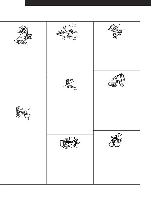
NOTE ON USE / HINWEISE ZUM GEBRAUCH /OBSERVATIONS RELATIVES A L’UTILISATION/ NOTE SULL’USO/NOTAS SOBRE EL USO / ALVORENS TE GEBRUIKEN / OBSERVERA
•Avoid high temperatures.
Allow for sufficient heat dispersion when installed on a rack.
•Vermeiden Sie hohe Temperaturen. Beachten Sie, daß eine ausreichend Luftzirkulation gewährleistet wird, wenn das Gerät auf ein Regal gestellt wird.
•Eviter des températures élevées
Tenir compte d’une dispersion de chaleur suffisante lors de l’installation sur une étagère.
•Evitate di esporre l’unità a temperature alte. Assicuratevi che ci sia un’adeguata dispersione del calore quando installate l’unità in un mobile per componenti audio.
•Evite altas temperaturas
Permite la suficiente dispersión del calor cuando está instalado en la consola.
•Vermijd hoge temperaturen.
Zorg voor een degelijk hitteafvoer indien het apparaat op een rek wordt geplaatst.
•Undvik höga temperaturer.
Se till att det finns möjlighet till god värmeavledning vid montering i ett rack.
•Handle the power cord carefully.
Hold the plug when unplugging the cord.
•Gehen Sie vorsichtig mit dem Netzkabel um. Halten Sie das Kabel am Stecker, wenn Sie den Stecker herausziehen.
•Manipuler le cordon d’alimentation avec précaution.
Tenir la prise lors du débranchement du cordon.
•Manneggiate il filo di alimentazione con cura. Agite per la spina quando scollegate il cavo dalla presa.
•Maneje el cordón de energía con cuidado. Sostenga el enchufe cuando desconecte el cordón de energía.
•Hanteer het netsnoer voorzichtig.
Houd het snoer bij de stekker vast wanneer deze moet worden aanof losgekoppeld.
•Hantera nätkabeln varsamt.
Håll i kabeln när den kopplas från el-uttaget.
•Keep the set free from moisture, water, and dust.
•Halten Sie das Gerät von Feuchtigkeit, Wasser und Staub fern.
•Protéger l’appareil contre l’humidité, l’eau et lapoussière.
•Tenete l’unità lontana dall’umidità, dall’acqua e dalla polvere.
•Mantenga el equipo libre de humedad, agua y polvo.
•Laat geen vochtigheid, water of stof in het apparaat binnendringen.
•Utsätt inte apparaten för fukt, vatten och damm.
•Unplug the power cord when not using the set for long periods of time.
•Wenn das Gerät eine längere Zeit nicht verwendet werden soll, trennen Sie das Netzkabel vom Netzstecker.
•Débrancher le cordon d’alimentation lorsque l’appareil n’est pas utilisé pendant de longues périodes.
•Disinnestate il filo di alimentazione quando avete l’intenzione di non usare il filo di alimentazione per un lungo periodo di tempo.
•Desconecte el cordón de energía cuando no utilice el equipo por mucho tiempo.
•Neem altijd het netsnoer uit het stopkontakt wanneer het apparaat gedurende een lange periode niet wordt gebruikt.
•Koppla ur nätkabeln om apparaten inte kommer att användas i lång tid.
•(For sets with ventilation holes)
•Do not obstruct the ventilation holes.
•Die Belüftungsöffnungen dürfen nicht verdeckt werden.
•Ne pas obstruer les trous d’aération.
•Non coprite i fori di ventilazione.
•No obstruya los orificios de ventilación.
•De ventilatieopeningen mogen niet worden beblokkeerd.
•Täpp inte till ventilationsöppningarna.
•Do not let foreign objects in the set.
•Keine fremden Gegenstände in das Gerät kommen lassen.
•Ne pas laisser des objets étrangers dans l’appareil.
•E’ importante che nessun oggetto è inserito all’interno dell’unità.
•No deje objetos extraños dentro del equipo.
•Laat geen vreemde voorwerpen in dit apparaat vallen.
•Se till att främmande föremål inte tränger in i apparaten.
•Do not let insecticides, benzene, and thinner come in contact with the set.
•Lassen Sie das Gerät nicht mit Insektiziden, Benzin oder Verdünnungsmitteln in Berührung kommen.
•Ne pas mettre en contact des insecticides, du benzène et un diluant avec l’appareil.
•Assicuratevvi che l’unità non venga in contatto con insetticidi, benzolo o solventi.
•No permita el contacto de insecticidas, gasolina y diluyentes con el equipo.
•Laat geen insektenverdelgende middelen, benzine of verfverdunner met dit apparaat in kontakt komen.
•Se till att inte insektsmedel på spraybruk, bensen och thinner kommer i kontakt med apparatens hölje.
•Never disassemble or modify the set in any way.
•Versuchen Sie niemals das Gerät auseinander zu nehmen oder auf jegliche Art zu verändern.
•Ne jamais démonter ou modifier l’appareil d’une manière ou d’une autre.
•Non smontate mai, nè modificate l’unità in nessun modo.
•Nunca desarme o modifique el equipo de ninguna manera.
•Nooit dit apparaat demonteren of op andere wijze modifiëren.
•Ta inte isär apparaten och försök inte bygga om den.
CAUTION
•The ventilation should not be impeded by covering the ventilation openings with items, such as newspapers, table-cloths, curtains, etc.
•No naked flame sources, such as lighted candles, should be placed on the apparatus.
•Please be care the environmental aspects of battery disposal.
•The apparatus shall not be exposed to dripping or splashing for use.
•No objects filled with liquids, such as vases, shall be placed on the apparatus.
3
ENGLISH
2 INTRODUCTION
Thank you for choosing the DENON DHT-M330DV HOME THEATER SYSTEM. This remarkable component has been engineered to provide superb surround sound listening with home theater sources such as DVD, as well as providing outstanding high fidelity reproduction of your favourite music sources.
As this product is provided with an immense array of features, we recommend that before you begin hookup and operation that you review the contents of this manual before proceeding.
2We greatly appreciate your purchase of this unit.
2To be sure you take maximum advantage of all the features this unit has to offer, read these instructions carefully and use the set properly. Be sure to keep this manual for future reference should any questions or problems arise.
“SERIAL NO.
PLEASE RECORD UNIT SERIAL NUMBER ATTACHED TO THE REAR OF THE CABINET FOR FUTURE REFERENCE”
TABLE OF CONTENTS
z BEFORE USING .......................................................................................... |
5 |
⁄1 LISTENING TO THE RADIO................................................................ |
42~46 |
x CAUTIONS ON INSTALLATION .............................................................. |
5, 6 |
⁄2 EXPANDING TO A 6.1- OR 7.1-CHANNEL SYSTEM .......................... |
47, 48 |
c CAUTIONS ON HANDLING ........................................................................ |
6 |
⁄3 DOLBY / DTS SURROUND................................................................. |
49~52 |
v FEATURES................................................................................................... |
6 |
⁄4 USING THE SLEEP TIMER ....................................................................... |
53 |
b CONNECTIONS .................................................................................... |
7~14 |
⁄5 SYSTEM FUNCTIONS............................................................................... |
54 |
n PART NAMES AND FUNCTIONS ....................................................... |
15~18 |
⁄6 LAST FUNCTION MEMORY ..................................................................... |
55 |
m REMOTE CONTROL UNIT.................................................................. |
19~26 |
⁄7 INITIALIZATION OF THE MICROPROCESSOR ........................................ |
55 |
, SETTING UP THE SYSTEM ................................................................ |
27~28 |
⁄8 TROUBLESHOOTING ............................................................................... |
56 |
. OPERATING THE SURROUND FUNCTIONS...................................... |
29~32 |
⁄9 SPECIFICATIONS ...................................................................................... |
57 |
⁄0 SURROUND PLAYBACK..................................................................... |
33~41 |
|
|
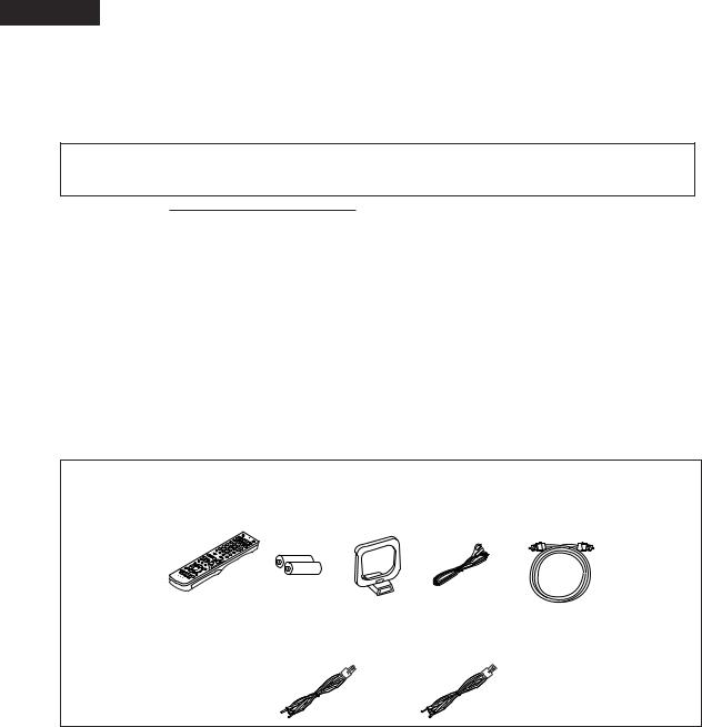
2 ACCESSORIES
Check that the following parts are included in addition to the main unit:
q Operating instructions ........................................ |
1 |
w Service station list |
.............................................. |
1 |
e Remote control unit (RC-996) |
.............................1 |
||
r R6P/AA batteries ................................................ |
2 |
t AM loop antenna ................................................ |
|
1 |
y FM indoor antenna ............................................. |
1 |
||
u Optical cable ....................................................... |
1 |
|
|
|
|
|
|
|
e |
|
|
|
r |
t |
y |
u |
|
|
|
|
|
|
|
|
|
|
i Cord A .................................................................................................... |
2 |
o Cord B........................................................................................ |
1 |
(Used to connect the Speakers) |
|
(Used to connect the Speakers) |
|
(Length: Approx. 10 meters) |
|
(Length: Approx. 3 meters) |
|
i |
|
o |
|
4
1 BEFORE USING
Pay attention to the following before using this unit:
•Moving the set
To prevent short circuits or damaged wires in the connection cords, always unplug the power cord and disconnect the connection cords between all other audio components when moving the set.
•Before turning the power switch on
Check once again that all connections are proper and that there are not problems with the connection cords. Always set the power switch to the standby position before connecting and disconnecting connection cords.
2CAUTIONS ON INSTALLATION
(1)AV SURROUND RECEIVER (AVR-M330)
Noise or disturbance of the picture may be generated if this unit or any other electronic equipment using microprocessors is used near a tuner or TV.
If this happens, take the following steps:
•Install this unit as far as possible from the tuner or TV.
•Set the antenna wires from the tuner or TV away from this unit’s power cord and input/output connection cords.
•Noise or disturbance tends to occur particularly when using indoor antennas or 300 Ω/ohms feeder wires. We recommend using outdoor antennas and 75 Ω/ohms coaxial cables.
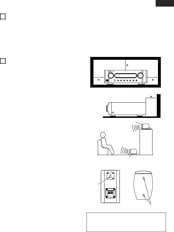
(2) SPEAKER SYSTEM (SYS-M330)
When installing, carefully examine the place and method of installation for safety.
When using a stand, brackets, etc., follow the instructions included with the stand or brackets and check for safety before installing and using. Denon will accept no responsibility for damages or accidents caused by the unit falling.
The quality of the sound produced from the speaker system is affected by the size and type (Japanese or Western) of the room, as well as by the method of installation. Consider the points listed below before installing the speaker system.
2Note that placing the speaker system on the same stand or shelf as a record player may result in howling.
2If there is a wall, glass door, etc., directly in front of or behind the speaker system, cover the wall or door with a thick curtain to prevent resonance and reflection.
2The SYS-M330 speaker systems are of the low-leakage-flux type and can be used near televisions, but depending on the TV there may be color blotching on the picture. If this happens, turn off the TV’s power, wait 15 to 30 minutes, then turn the TV’s power back on. The TV’s automatic degaussing circuit should reduce the blotching on the picture. If blotching persists, move the speaker further away.
2Set the center speaker (SC-CM330) so that its front surface is facing upwards or downwards, according to the place of installation. We recommend setting it so that the front surface is facing downwards when installed at a position above the ears, upwards when installed on the floor. Use the included pedestal to adjust the angle of installation as shown on the diagram at the right.
2When mounting the satellite speaker system (SC-AM330) on a stand or bracket, M5 nuts are inserted into the bottom of the satellite speaker system (SC-AM330) at intervals of 60 mm. When mounting, following the instructions in the manual included with the speaker stand or ceiling mount bracket, and be sure to install properly and securely.
ENGLIS
•Store this instructions in a safe place.
After reading, store this instructions along with the warranty in a safe place.
•Note that the illustrations in this instructions may differ from the actual set for explanation purposes.
For heat dispersal, leave at least 10 cm/4 inch of space between the top, back and sides of this unit and the wall or other
components. |
10 cm/4 inch or more |

 10 cm/4 inch or more
Wall |
Center speaker (SC-CM330)
[ Example of installation ]
Facing downwards
Facing upwards
Center speaker (SC-CM330)
[ Rear of front/surround speaker |
[ Bottom of front/surround |
(SC-AM330) ] |
speaker (SC-AM330) ] |
Wall mount hook
Speaker STAND/speaker bracket mount screw hole
CAUTION:
•To ensure safety, do not place any objects on top or lean objects against the speaker system.
•The speaker may topple down or fall if force is applied to the sides. Be particularly careful to avoid this, as this could cause injury or other serious accidents.
5
ENGLISH
WARNING:
•When installing the speaker systems on the ceiling or wall, to ensure safety, have specialists do the installation work.
•Be sure to fasten the speaker cords to a wall, etc., to prevent people from tripping over them or otherwise pulling on them accidentally, causing the speaker systems to fall.
•Be sure to check for safety after installing the speaker systems. Afterwards, perform safety inspections at regular intervals to be sure there is no danger that the speaker systems will fall. Denon will accept no responsibility for damages or accidents caused by inappropriate choice of the place of installation or improper installation procedures.
3CAUTIONS ON HANDLING
(1)AV SURROUND RECEIVER (AVR-M330)
•Switching the input function when input jacks are not connected
A clicking noise may be produced if the input function is switched when nothing is connected to the input jacks. If this happens, either turn down the MASTER VOLUME control or connect components to the input jacks.
•Muting of PRE OUT jacks, HEADPHONE jack and SPEAKER terminals
The PRE OUT jacks, HEADPHONE jacks and SPEAKER terminals include a muting circuit. Because of this, the output signals are greatly reduced for several seconds after the power switch is turned on or input function, surround mode or any other-set-up is changed. If the volume is turned up during this time, the output will be very high after the muting circuit stops functioning. Always wait until the muting circuit turns off before adjusting the volume.
•Whenever the power switch is in the STANDBY state, the apparatus is still connected on AC line voltage. Please be sure to unplug the cord when you leave home for, say, a vacation.
(2) SPEAKER SYSTEM (SYS-M330)
•Note that color blotching may occur on a TV, etc., due to interaction with the speaker system if there is a magnet or an object generating magnetic force nearby.
Examples: (a) When there are magnets on the door of the rack, stand, etc.
(b)When a health device, etc., equipped with magnets is placed nearby.
(c)When toys or other objects using magnets are placed nearby.
•Note that the illustrations in this instructions may differ from the actual set for explanation purposes.
•Be sure to keep the operating instructions.
After reading these operating instructions, store them in a safe place. We also recommend filling in the necessary items on the back cover.
4FEATURES
1.Dolby Digital
Using advanced digital processing algorithms, Dolby Digital provides up to 5.1 channels of wide-range, high fidelity surround sound. Dolby Digital is the default digital audio delivery system for DVD.
2.DTS (Digital Theater Systems)and DTS NEO:6
DTS provides up to 5.1 channels of wide-range, high fidelity surround sound, from sources such as laser disc, DVD and speciallyencoded music discs.
The AVR-M330 can be also decoded with DTS Neo:6, a surround mode allowing 5.1 channels playback of regular stereo sources.
3.DOLBY PRO LOGIC II Game mode compatibility
In addition to the previously offered Music and Cinema modes, the AVR-M330 also offers a Game mode optimum for games.
4.Dolby Virtual Speaker compatibility
Dolby Virtual Speaker is an proprietary technology of Dolby Laboratories. A high performance digital signal processor enables playback of Dolby Digital and DTS multi-channel surround signals in the Dolby Virtual Speaker mode. Surround sound can be achieved with the Dolby Virtual Speaker mode for CDs and other 2-channel sources in combination with the Dolby Pro Logic II decoder.
5.Remote control unit with preset memory function
The AVR-M330 comes with a remote control unit equipped with a preset memory function including the remote control operation
codes for DVD-M330 DVD player, MD recorders, cassette decks and DENON remote control compatible components as well as the remote control operation codes of other major brands of TVs and video decks.
6.Convenient system functions
When system connections are made with a DVD-M330 DVD player, such system functions as auto function selection, synchronized recording can be performed easily.
7.Equipped with 6.1- and 7.1-channel playback expansion function (surround back channel pre-out connectors)
When the 6.1- or 7.1-channel mode is set with the Quick Setup function, the unit is compatible with decoding of various types of multi-channel formats.
•Dolby Digital EX
•DTS-ES
•Dolby ProLogic IIx

 A commercially available amplifier and speaker must be connected to the DHT-M330DV’s surround back channel pre-out connector in order to achieve 6.1- and 7.1-channel playback.
6

ENGLIS
5 CONNECTIONS
•Do not plug in the AC cord until all connections have been completed.
•Be sure to connect the left and right channels properly (left with left, right with right).
•Insert the plugs securely. Incomplete connections will result in the generation of noise.
•Note that binding pin plug cords together with AC cords or placing them near a power transformer will result in generating hum or other noise.
•Noise or humming may be generated if a connected audio equipment is used independently without turning the power of this unit on. If this happens, turn on the power of the this unit.
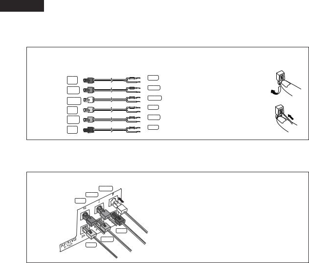
(1) Speaker system connections
•When connecting, use connection cords A and B included with the DHT-M330DV. The connection cords are color-coded by different colored plugs and labels. Connect in such a way that the colors are the same as the AV surround receiver’s speaker terminals.
•Connect the side of the included connection cord with the colored label to the “+” (plus) side.
FRONT SPEAKER-R |
CENTER SPEAKER |
FRONT SPEAKER-L |
(SC-AM330) |
(SC-CM330) |
(SC-AM330) |
FR |
C |
FL |
Red |
Green |
White |
|
Cord B (3m) |
|
|
|
Cord B (3m) |
AV SURROUND RECEIVER (AVR-M330)
Cord A (10m) |
Cord B (3m) |
Cord A (10m) |
Gray |
Purple |
Blue |
SR |
SW |
SL |
SURROUND SPEAKER R |
SUBWOOFER |
SURROUND SPEAKER L |
(SC-AM330) |
(DSW-M330) |
(SC-AM330) |
[ Description of speaker label ]
•Use connection cords of the colors corresponding to the position of speaker installation, and connect to the AV surround amplifier.
Precautions when connecting speakers
If a speaker is placed near a TV video monitor, the colors on the screen may be disturbed by the speaker’s magnetism. If this should happen, move the speaker away to a position where it does not have this effect.
White Red Blue Gray
7
ENGLISH
Be sure to turn the amplifier’s power off when connecting the speaker systems.
•Use the included cables to connect the input terminals on the back of the speaker systems (see diagram) to the amplifier’s speaker output terminals. Inverting the polarities will result in unnatural sound, with the phase off or no low bass sound.
•Connect the side of the included connection cord with the colored label to the “+” (plus) side.
•Connect connection cords A (10 meters) and B (3 meters) as follows:
To the AVC-M330’s speaker terminals
|
(3m) |
FR |
Red |
|
(3m) |
C |
Green |
FL |
(3m) |
White |
|
|
(10m) |
SR |
Gray |
(3m)
SW Purple
(10m)
SL Blue
To the various speaker terminals
|
+ |
q Press the terminal’s lever down. |
|
Red |
|
|
– |
w Insert the cord’s core wires into the hole. |
|
+ |
|
|
Green |
|
|
||
|
– |
e Release the lever. |
|
+ |
|
|
White |
|
|
||
|
– |
|
|
+ |
Gray |
|
||
|
– |
|
|
+ |
Purple |
|
– |
|
|
+ |
Blue |
|
– |
|
Connecting the speaker cords
Use the included connection cords to connect the input terminals on the backs of the speaker systems (see the diagram) to the AVR-M330’s speaker output terminals.
• Insert the connection cords’ plugs securely to the back. Incomplete connections will cause noise and malfunction.
White
Green
Red

 Lock lever
Blue
Purple
Gray
q Connect according to the speaker terminals’ colors.
wInsert the plug securely to the back until a click is heard. Red, green and white: Raise the lock lever to insert. Gray, violet and blue: Lower the lock lever to insert.
e To disconnect, press the lock lever and pull out.
8
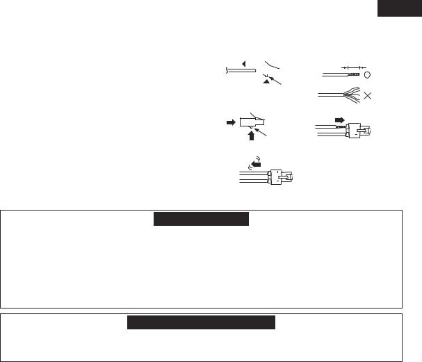
Replacing the speaker connection cords
• The speaker connection cords can be replaced, for example when you want to extend the included connection cords.
qPress the release button on the side opposite the lock level to detach the cord from the plug.
wPeel off the sheathing at the tip of the cord you want to replace, and twist firmly so the tip remains tightly wound.
ePressing the release button, insert the core wires, making sure to match the cord’s “+” and “–” polarities with the “+” and “–” sides of the plug.
rRelease the release button, then gently pull on the cord to check that it is firmly attached.
q |
|
|
|
|
w |
|
|
|
|
|
|
|
|
|
|
|
|
|
|
|
|
|
|
|
|
|
|
|
|
 release button
e
release button
r
ENGLIS
10mm
Protector circuit
•The AV surround amplifier (AVC-M330) is equipped with a built-in protection circuit. The purpose of this circuit is to cut off the output to the speakers in order to protect them under circumstances such as when the output of the amplifier is inadvertently short-circuited and a large current flows or when there is an extremely large output.
The protection circuit is also activated when the internal temperature is unusually high. (When the protection circuit is activated due to high internal temperature, the volume indicator flashes and the speaker output is restricted. If the internal temperature rises further, the power is set to the standby mode and the power indicator flashes red.) In such cases, be sure to unplug the AV surround amplifier’s power cord from the power outlet, check the wiring of the connection cords and input cords for any abnormalities, and if the AV surround amplifier’s temperature is extremely high, wait for it to cool down, improve ventilation around the amplifier, then turn the power back on.
If the protection circuit is activated even though there are no problems with the wiring or with ventilation around the AV surround amplifier, there may be a problem with the AV surround amplifier. Unplug the AV surround amplifier’s power cord from the power outlet, then contact a DENON service or repair center.
Note on speaker impedance
•The protector circuit may be activated if the set is played for long periods of time at high volumes when speakers with an impedance lower than the specified impedance (for example speakers with an impedance of lower than 4 Ω/ohms) are connected. If the protector circuit is activated, the speaker output is cut off. Turn off the set’s power, wait for the set to cool down, improve the ventilation around the set, then turn the power back on.
9
ENGLISH
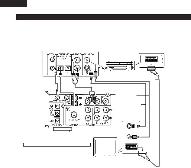
(2) Connecting the DVD Player and TV
•Connect the DVD player’s video signals directly to the TV and switch the picture on the TV.
•When making connections, also refer to the operating instructions of the other components.
Connecting the AUDIO Jack |
|
Connecting the DIGITAL Jack |
•Connect the video disc player’s analog audio output jacks (ANALOG AUDIO OUT) to the DVD IN jacks using pin plug cords.
•Use a commercially available optical transmission cable for connection to the optical transmission terminal (OPTICAL).
DVD VIDEO PLAYER (DVD-M330)
|
|
SCART cord |
|
System Cord |
Optical Cord |
Audio cord |
|
|
|
VIdeo cord |
|
|
|
S VIdeo cord |
|
AV SURROUND RECEIVER |
S-VIDEO IN |
||
TV |
|||
(AVR-M330) |
|
||
|
|
||
|
|
VIDEO IN |
|
Connecting the VIDEO Jack (DVD-M330) |
|
||
• Connect the TV’s video input jack (VIDEO INPUT)to the DVD’s |
IN |
||
|
|||
VIDEO OUT jack using a 75Ω/ohms video cord. |
|
||
10
ENGLIS
(3) Connecting the Audio Signals of a Digital Satellite Tuner and VCR
•Connect the video signals directly to the TV and switch the picture on the TV.
•When making connections, also refer to the operating instructions of the other components.
Connection to the optical digital input terminal
•Only audio signals are input to the optical digital input terminal.
•Use a commercially available optical transmission cable for connection to the optical transmission terminal (OPTICAL).
Digital satellite/cable tuner
B
OPTICAL |
AUDIO |
OUT |
OUT |
R L |
Connection of a digital satellite/cable tuner
•For tuners equipped with an optical digital output terminal, connect the digital output terminal to the DIGITAL TV/AUX1 IN terminal on the AVR-M330 using an optical transmission cable.
•To connect the audio output terminals, use whatever of the AVR-M330’s TAPE terminals are open.
R L
AV SURROUND RECEIVER (AVR-M330)
L |
R |
L |
R |
L |
R |
Connection of a video deck
•Connect the video deck’s audio output and audio input terminals to whatever of the AVR-M330’s TAPE terminals are open using pin-plug cords.
R |
L |
R |
L |
Video deck |
|
|
|
R |
L |
R |
L |
OUT |
|
IN |
|
|
|
AUDIO |
|
11
ENGLISH
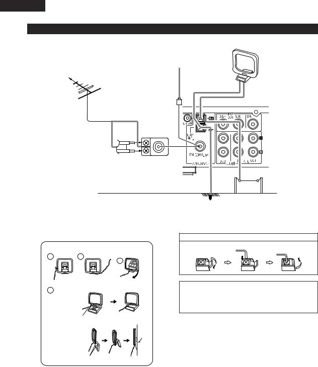
(4) Connecting the antenna terminals
AM LOOP ANTENNA (Supplied)
FM INDOOR ANTENNA
DIRECTION OF (Supplied)
BROADCASTING
STATION
FM ANTENNA
75 Ω/ohms COAXIAL CABLE
FM ANTENNA ADAPTER (Option)
AM OUTDOOR
ANTENNA
GROUND
•An PAL-type FM antenna cable plug can be connected directly.
•If the FM antenna cable’s plug is not of the PAL-type, connect using the PAL-type antenna adapter (Option).
AM loop antenna assembly
1 |
2 |
Remove the vinyl tie and take out the
connection line.
4
a.With the antenna on top any stable
surface.
Mount
b.With the antenna attached to a wall.
Connect to the AM antenna terminals.
3
Bend in the reverse direction.
Connection of AM antennas
1. Push the lever. |
2. Insert the conductor. |
3. Return the lever. |
|||
|
|
|
|
|
|
|
|
|
|
|
|
|
|
|
|
|
|
|
|
|
|
|
|
|
|
|
|
|
|
NOTES:
•Do not connect two FM antennas simultaneously.
•Even if an external AM antenna is used, do not disconnect the AM loop antenna.
•Make sure AM loop antenna lead terminals do not touch metal parts of the panel.
Installation hole Mount on wall, etc.
12
ENGLIS
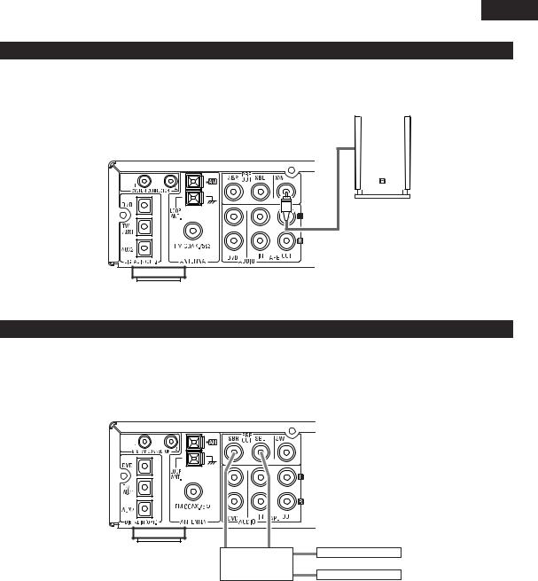
(5) Using the active subwoofer
•Use Subwoofer jack to connect in case you had additional active subwoofer.
•You can connect a larger active subwoofer to the system. Connect the active subwoofer to the SW (Subwoofer) PRE-OUT jack using a shielded audio cable.
AV SURROUND RECEIVER (AVR-M330)
ACTIVE SUBWOOFER
(6) Using SURROUND BACK PRE OUT (SBL/SBR)
•Use SURR. BACK PRE OUT jack to connect additional POWER AMPLIFIER and speaker systems. You can enjoy 6.1CH or 7.1CH surround system.
•When making connections, also refer to the operating instructions of the other components.
•To make the 6.1 or 7.1-channel setting, set the speakers to “6.1CH” or “7.1CH” in the quick setup and select “Room Setup” . (See pages 27 .)
AV SURROUND RECEIVER (AVR-M330)
IN IN
POWER AMPLIFIER (for SURR. BACK ch)
SURR. BACK (L) Speaker
SURR. BACK (R) Speaker
•Connect the power amplifier for SURR. BACK speaker system.
13

ENGLISH
(7) Connecting the audio components (DVD-M330)
•The AVR-M330 can be used connected in a system with the DVD-M330 DVD player.
•For instructions on operating the DVD-M330 DVD player, refer to their respective operating instructions.
•Only the DVD-M330 DVD player can be connected directly to the AVR-M330 using system connections.
NOTES:
•This system includes digital circuitry which may cause interference such as color blotching or changes in the color on TVs. If this happens, move the system and the TV as far apart as possible.
•Do not plug the power cord into the power outlet until all connections are completed. Be sure to interconnect the channels (L to L (white) and R to R (red)) properly, as shown on the diagram.
•Insert the plugs securely. Incomplete connections may result in noise.
•Be sure to connect the speaker cords between the speaker terminals and the speaker systems with the same polarities ( + to +, – to – ). If the polarities are switched, the sound at the center will be weak, the position of the different instruments will be unclear, and the stereo effect will be lost.
•After unplugging the power cord, wait about 5 seconds before plugging it back in.
•Note that setting the connection cords (pin-plug cords) next to the power cords may result in humming or other noise.
CAUTION:
•Only one DVD player can be connected to the AVR-M330 using system connections. System operations cannot be performed properly if two DVD player are connected using system connections.
•Whenever the power operation switch is in the STANDBY position, the unit is still connected to AC line voltage.
•Please be sure to unplug the power cord when you leave home for, e.g.,a vacation, etc.
System operations
Such system operations as the auto power on functions, as well as remote control operations cannot be performed unless all the RCA pin-plug cords and system connector cords are connected between the units, so be sure to make all the connections properly as shown in the diagram. Also, disconnecting system connectors while the system is operating may result in malfunctions. Be sure to unplug the power cord before changing connections.
Connecting the speaker systems
Connect the speaker system for the left channel (the left side as seen from the front) to the L terminals, the speaker system for the right channel to the R terminals. Refer to the instructions supplied with the speaker system for details. Be sure to use speaker systems with an impedance of 6 Ω/ohms or greater.
AV SURROUND RECEIVER |
Connecting the 5.1ch speaker |
(AVR-M330) |
|
|
AC CORD |
|
AC 230 V, 60 Hz |
System cords |
audio cord |
|
AC CORD |
|
AC 230 V, 50 Hz |
DVD PLAYER |
|
(DVD-M330) |
TV |
|
Optical cord |
14
ENGLIS
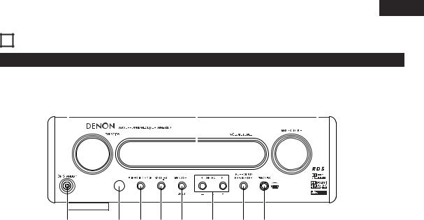
6 PART NAMES AND FUNCTIONS
AV SURROUND RECEIVER (AVR-M330) Front Panel
• For details on the functions of these parts, refer to the pages given in parentheses ( ).
!1 |
|
!0 |
|
|
|
|
o |
|||||||||
|
|
|
|
|
|
|
|
|
|
|
|
|
|
|
|
|
|
|
|
|
|
|
|
|
|
|
|
|
|
|
|
|
|
|
|
|
|
|
|
|
|
|
|
|
|
|
|
|
|
|
|
|
|
|
|
|
|
|
|
|
|
|
|
|
|
|
|
|
|
|
|
|
|
|
|
|
|
|
|
|
|
|
|
|
q w e r t y u i
q Power operation switch (ON/STANDBY).................................. |
|
(29) |
w Remote control sensor............................................................. |
|
(19) |
e Surround mode button (SURROUND MODE).......................... |
|
(30) |
r Super Dynamic Bass/Preset EQ button (SDB/P.EQ) |
................(32) |
|
t Menu/set button (MENU/SET) ..................................... |
|
(27, 31, 42) |
y Select button (SELECT 0 and 1)......................... |
(31, 37, 38, 42) |
|
u i o
!0Display |
|
!1Function selector knob (FUNCTION)........................................ |
(30) |
15
ENGLISH
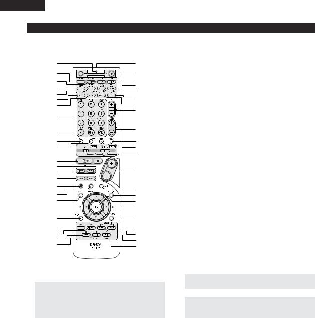
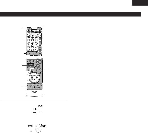
Remote control unit
•For details on the functions of these parts, refer to the pages given in parentheses ( ).
•Some of the buttons on the remote control unit have some functions.
The functions are switched using the remote control mode selector switches.
q |
@4 |
|
w |
@5 |
|
e |
@6 |
|
@7 |
||
r |
||
@8 |
||
t |
||
@9 |
||
y |
||
#0 |
||
u |
||
|
||
|
#1 |
|
i |
|
|
o |
#2 |
|
|
||
!0 |
#3 |
|
!1 |
#4 |
|
|
#5 |
|
!2 |
|
|
!3 |
#6 |
|
!4 |
||
!5 |
|
|
!6 |
#7 |
|
|
||
!7 |
#8 |
|
!8 |
#9 |
|
|
||
|
$0 |
|
!9 |
$1 |
|
@0 |
$2 |
|
@1 |
$3 |
|
@2 |
$4 |
@3 |
$5 |
|
q Transmission indicator
w Sleep timer button ...................................................................(53) e NTSC/PAL button
r Clear button
t A-B repeat button y Program/direct u Repeat button
i Input source/surround mode selector button
* System buttons...................................................(18, 20, 21, 26)
o |
Call button |
|
!0Test tone button ....................................................................... |
(33) |
|
!1Input mode selector button...................................................... |
(30) |
|
!2DVD play button |
|
|
!3DVD stop button |
|
|
!4DVD skip buttons |
|
|
!5DVD search buttons |
|
|
!6DVD pause button |
|
|
!7Sound enhancer button............................................................ |
(32) |
|
!8 |
|
|
DVD Setup button |
|
|
!9Channel select button ........................................................ |
(33, 39) |
|
|
|
|
@0 |
Return button |
|
@1 |
Display button |
|
@2 |
Angle button |
|
@3 |
Audio selector button |
|
@4Remote control signal transmission window........................... |
(19) |
|
@5Power button............................................................................ |
(29) |
|
@6* System buttons................................................... |
(18, 20, 21, 26) |
|
|
|
|
@7 |
Zoom button |
|
@8 |
Slide mode button |
|
@9 |
CD SRS button |
|
#0 |
Random button |
|
#1Tuner tuning +/– buttons .......................................................... |
(42) |
|
#2Tuner preset +/– buttons.................................................... |
(43, 44) |
|
#3Function selector button .......................................................... |
(29) |
|
#4Surround mode selector button ............................................... |
(30) |
|
#5Mode selector switches(1 and 2) .................... |
(17, 18, 20, 21, 26) |
|
#6Main volume control buttons ................................................... |
(31) |
|
#7Muting button........................................................................... |
(32) |
|
#8SDB/P.EQ button ...................................................................... |
(32) |
|
#9 |
Enter button |
|
$0Cursor button |
|
|
.........................................$1Surround parameter button |
(34~36, 38) |
|
$2Top menu button |
|
|
$3Menu button |
|
|
$4Subtitle button |
|
|
.........................................................$5* System buttons |
(18, 20, 26) |
|
•For details on the function and operation of the various parts, refer to the pages indicated in (parentheses).
•Buttons indicated  are DVD control buttons and can be operated when the remote control mode selector switch is set to the
  position.
•The functions of the system buttons (*) are switched using the remote control mode selector switch.
16
ENGLIS
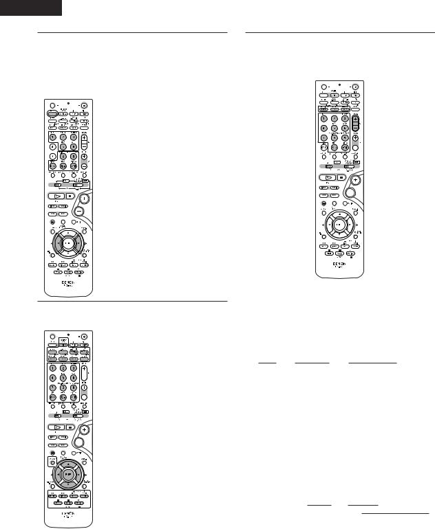
Names and functions of remote control unit buttons on the DHT-M330DV
•Buttons in sections q ~ e can be operated regardless of the position of mode switches 1 and 2.
•Consider  as standard positions, and switch as necessary to operate.
q
3


 e q
e q 


1 


 2
2
w
q
3 


 q
q 


3
1 |
Set mode switch 1 to the “DVD” position. |
||||
|
|
|
|
|
|
|
|
|
|
|
|
|
|
|
|
|
|
|
|
|
|
|
|
q Surround amplifier control buttons
ON |
: Turns the AVR-M330’s power on. |
OFF |
: Turns the AVR-M330’s power off. |
FUNCTION |
: Function selection (in order) |
SURROUND |
: Surround mode selection |
INPUT MODE : Input mode selection |
|
TEST TONE |
: Test tone on/off |
+ |
: Main volume up |
– |
: Main volume down |
MUTING |
: Muting on/off |
SOUND ENHANCER: Sound enhancer selection |
|
SDB/P.EQ |
: SDB/P.EQ selection and setting |
SURROUND |
: Surround parameter selection and setting |
PARAMETER |
|
CH SELECT |
: Channel level/Delay time selection and setting |
w DVD control buttons
1: Play (auto power on and auto function selection)
2 |
: Stop |
8, 9 |
: Skip (cueing) |
6, 7 |
: Search (fast-reverse and fast-forward) |
3: Pause and frame-by-frame
e Tuner control buttons
CH +/– |
: Preset channel up/down |
|
(auto power on and auto function selection) |
2 |
Set mode switch 2 to the position of the function you want to |
|||||||||
|
||||||||||
|
operate (DVD, TUNER or AMP.). |
|||||||||
|
|
|
|
|
|
|
|
|
|
|
|
|
|
|
|
|
|
|
|
|
|
|
|
|
|
|
|
|
|
|
|
|
|
|
|
|
|
|
|
|
|
|
|
17
ENGLISH
3 |
Operate the DHT-M330DV. |
|
|
[1] Surround amplifier system buttons |
|
|
(Operated with mode switch 2 set to “AMP.”) |
|
|
• These operations are possible with mode switch 1 at |
|
|
any position. |
|
|
SLEEP |
: Sleep on/off |
|
DVD |
: Function DVD |
|
TUNER |
: Function TUNER |
|
TV/AUX1 |
: Function TV/AUX1 |
|
TAPE |
: Function TAPE |
|
AUX2 |
: Function AUX2 |
|
5CH STEREO : 5ch stereo mode set |
|
|
AUTO DECODE : Auto decode mode set |
|
|
VIRTUAL |
: Dolby VS surround mode |
|
|
set or 2.1/3.1/5.1ch mode |
|
|
switching when Dolby VS |
|
|
mode |
|
STEREO |
: Stereo mode set |
|
DIRECT |
: Direct mode set |
|
0, 1 |
: Selection left and right |
[2]DVD system buttons
(Operated with mode switch 2 set to “DVD”)
|
|
|
|
|
|
|
|
|
|
|
NTSC/PAL |
: NTSC/PAL selection |
|
|
|
|
|
|
|
|
|
|
|
ZOOM |
: Zoom on/off |
|
|
|
|
|
|
|
|
|
|
|
SLIDE MODE : JPEG image slide mode |
|
|
|
|
|
|
|
|
|
|
|
|
|
selection |
|
|
|
|
|
|
|
|
|
|
|
A-B REPEAT |
: A-B repeat playback setting |
|
|
|
|
|
|
|
|
|
|
|
CLEAR |
: Program clear |
|
|
|
|
|
|
|
|
|
|
|
||
|
|
|
|
|
|
|
|
|
|
|
SEARCH MODE: Title and chapter search |
|
|
|
|
|
|
|
|
|
|
|
|||
|
|
|
|
|
|
|
|
|
|
|
|
selection |
|
|
|
|
|
|
|
|
|
|
|
|
|
|
|
|
|
|
|
|
|
|
|
|
RANDOM |
: Random play on/off |
|
|
|
|
|
|
|
|
|
|
|
REPEAT |
: Repeat play setting |
|
|
|
|
|
|
|
|
|
|
|
PROG/DIRECT : Program/direct play |
|
|
|
|
|
|
|
|
|
|
|
|
|
selection |
|
|
|
|
|
|
|
|
|
|
|
|
|
|
|
|
|
|
|
|
|
|
|
|
CALL |
: Program call |
|
|
|
|
|
|
|
|
|
0 ~ 9, +10 |
: Number buttons |
||
|
|
|
|
|
|
|
|
|
|
|
DVD SETUP |
: DVD setup mode on/off |
|
|
|
|
|
|
|
|
|
|
|
||
|
|
|
|
|
|
|
|
|
|
|
•, ª, 0, 1 |
: Cursor up,down,left,right |
|
|
|
|
|
|
|
|
|
|
|
ENTER |
: Enter setting |
|
|
|
|
|
|
|
|
|
|
|
TOP MENU |
: Top menu call |
|
|
|
|
|
|
|
|
|
|
|
MENU |
: Menu call |
|
|
|
|
|
|
|
|
|
|
|
DISPLAY |
: Display call/selection |
|
|
|
|
|
|
|
|
|
|
|
RETURN |
: Menu return |
|
|
|
|
|
|
|
|
|
|
|
SUBTITLE |
: Subtitle language selection |
|
|
|
|
|
|
|
|
|
|
|
AUDIO |
: Audio language selection |
|
|
|
|
|
|
|
|
|
|
|
ANGLE |
: Angle selection |
|
|
|
|
|
|
|
|
|
|
|
|
|
[3]Tuner system buttons
(Operated with mode switch 2 set to “TUNER”)
|
|
|
|
|
|
|
|
|
|
|
|
|
|
|
|
|
|
|
|
|
|
|
|
|
|
|
|
|
|
|
|
|
|
|
|
|
|
|
|
|
|
|
|
|
|
|
|
|
|
|
|
BAND |
: FM/AM band selection |
|||||||||||
MEMO |
: Preset memory |
|||||||||||
MODE |
: FM auto/mono mode selection |
|||||||||||
TUNER +/– |
: Tuning up/down |
|||||||||||
|
0 ~ 9, +10 : Preset channel number buttons |
||||||||||||
RDS |
: Use this button to automatically tune to stations using the |
||||||||||||
|
radio data system. |
|
|
|
|
|
|
|
|
|
|||
|
1 RDS |
|
|
1 PTY |
|
|
1 |
TP |
|
|
|||
|
|
|
|
|
|
OFF 0 |
|
|
|
|
|
|
|
|
|
|
|
|
|
|
|
|
|
|
|
||
PTY |
: Press this button after selecting“PTY” with the RDS button |
||||||||||||
|
to select one of the 29 program types. |
||||||||||||
CT |
: Use this to display the time of the clock on the AVR-M330. |
||||||||||||
|
Press this button when the time service of an RDS station |
||||||||||||
|
is being properly received. “TIME” is displayed for 4 |
||||||||||||
|
seconds. “NO TIME DATA” is displayed if the RDS station |
||||||||||||
|
does not offer a time service and when the broadcast is not |
||||||||||||
|
being received properly. |
|
|
|
|
|
|||||||
RT |
: Press this button when receiving RDS stations to select the |
||||||||||||
|
frequency, PS (or Station name), PTY or RT display. |
||||||||||||
|
Note that this button will not function if the reception is |
||||||||||||
|
poor. |
|
|
|
|
|
|
|
|
|
|||
|
The display mode changes as follows each time the button |
||||||||||||
|
is pressed. |
|
|
|
|
|
|
|
|
|
|||
|
|
1 PS |
|
1 |
RT |
|
1 |
PTY |
|
|
|||
|
|
|
|
|
Frequency |
0 |
|
|
|
|
|||
|
|
|
|
|
|
|
|
|
|||||
|
|
|
|
|
|
|
|
|
|
|
|
|
|
18
Loading...