


 Loading...
Deploying FCoE (FIP Snooping) on Dell PowerConnect 10G Switches: M8024-k, 8024 and 8024F
A Dell Deployment Guide
Authors
Network Enabled Solutions Team,
Kevin Locklear
Contributor
Kili Land
Deploying FCoE (FIP Snooping) on Dell PowerConnect 10G Switches: M8024-k, 8024, and 8024F
This document is for informational purposes only and may contain typographical errors and technical inaccuracies. The content is provided as is, without express or implied warranties of any kind.
© 2011 - 2012 Dell Inc. All rights reserved. Dell and its affiliates cannot be responsible for errors or omissions in typography or photography. Dell, the Dell logo, PowerConnect and PowerEdge are trademarks of Dell Inc. Intel and Xeon are registered trademarks of Intel Corporation in the U.S. and other countries. Microsoft, Windows, and Windows Server are either trademarks or registered trademarks of Microsoft Corporation in the United States and/or other countries. Other trademarks and trade names may be used in this document to refer to either the entities claiming the marks and names or their products. Dell disclaims proprietary interest in the marks and names of others.
March 2012| Rev 2.0
2
Deploying FCoE (FIP Snooping) on Dell PowerConnect 10G Switches: M8024-k, 8024, and 8024F |
|
Contents |
|
Introduction ........................................................................................................... |
6 |
Basic Terminology .................................................................................................... |
6 |
FIP snooping ........................................................................................................ |
6 |
FIP snooping bridge (FSB) ........................................................................................ |
6 |
FCF ................................................................................................................... |
6 |
PFC................................................................................................................... |
7 |
NPIV.................................................................................................................. |
7 |
NPV................................................................................................................... |
7 |
VSAN ................................................................................................................. |
7 |
Configuration scenarios ............................................................................................. |
8 |
Important notes prior to deployment .......................................................................... |
9 |
Scenario 1: Deploying the Dell PowerConnect 8024 Series FSB in a Cisco 5000 Series Switch (NPIV) |
|
environment.......................................................................................................... |
10 |
Configuring the Dell PowerConnect M8024-k,8024, and 8024F for FIP Snooping ....................... |
13 |
Configuring the Cisco 5000 series switch with firmware ver 5.x for a single connection from the |
|
Dell PowerConnect M8024-k or 8024()(F) ..................................................................... |
17 |
Basic Validation for the PowerConnect M8024-k configuration ........................................... |
23 |
Basic Troubleshooting Areas .................................................................................... |
28 |
Scenario 2: Configuring Multiple Uplinks into LAG for Cisco Nexus 5000 Series Switch (NPIV) |
|
Environment.......................................................................................................... |
30 |
Configuring the Cisco Nexus 5000 series switch with firmware ver 5.x for a multiple link LAG (link |
|
aggregation) connection at the Top-of-Rack. ................................................................ |
31 |
Configuring the M8024-k,8024, and 8024F for FIP Snooping ............................................... |
33 |
Scenario 3: Configuring Multiple Uplinks into LAG for Cisco Nexus 5000 Series Switch (NPV mode) |
|
Environment.......................................................................................................... |
35 |
Configuring the Cisco Nexus 5000 series switch with firmware ver 5.0(3)N2(2a) in NPV mode |
for a |
multiple link LAG (link aggregation) connection from the Dell PowerConnect M8024-k or 8024()(F) |
|
...................................................................................................................... |
36 |
Configuring the Dell PowerConnect M8024-k,8024,and 8024F for FIP Snooping with Cisco Nexus |
|
5000 series switch in NPV mode................................................................................ |
37 |
ETS Behavior and CoS configurations on the PowerConnect 8024 series switches ..................... |
37 |
Updating firmware .................................................................................................. |
39 |
Command-line interface method............................................................................... |
39 |
Web interface method ........................................................................................... |
41 |
Appendix A – Full CLI examples ................................................................................... |
45 |
M8024-k CLI example............................................................................................. |
45 |
|
3 |

Deploying FCoE (FIP Snooping) on Dell PowerConnect 10G Switches: M8024-k, 8024, and 8024F |
|
Cisco Nexus 5548UP CLI example .............................................................................. |
52 |
Appendix B - Network Switch Versions........................................................................... |
56 |
References............................................................................................................ |
56 |
About Dell ............................................................................................................ |
56 |
Figures |
|
|
Figure 1. |
Dell PowerConnect™ M8024-k Switch (10G Ethernet) .............................................. |
6 |
Figure 2. |
Dell PowerConnect™ 8024F (10G Ethernet) ......................................................... |
6 |
Figure 3. |
General overview of deployment...................................................................... |
8 |
Figure 4. |
Disabling simple mode .................................................................................. |
9 |
Figure 5. |
Simple 1-link connection between devices ......................................................... |
10 |
Figure 6. |
General Overview of the whole configuration and planning procedure ........................ |
11 |
Figure 7. |
Overview of parallel configuration ................................................................... |
12 |
Figure 8. |
Example commands for Dell PowerConnect M8024-k (can be copied and pasted) ........... |
13 |
Figure 9. |
Configuration overview of Dell PowerConnect M8024-k .......................................... |
16 |
Figure 10. |
Sample CLI for Cisco Nexus 5020 (can be copied and pasted) ................................... |
17 |
Figure 11. |
Sample CLI for Cisco Nexus 5548 (can be copied and pasted) ................................... |
18 |
Figure 12. |
Cisco Nexus 5000 series configuration sequence................................................... |
20 |
Figure 13. |
M1000e Chassis Management Controller -> Server Overview -> Properties -> WWN/MAC |
|
information for Blade Server 3’s “B” fabric CNA port 2 (B2). ............................................ |
21 |
|
Figure 14. |
Example of show interface brief command ......................................................... |
22 |
Figure 15. |
show spanning-tree summary command showing current configuration with ports states.. |
23 |
Figure 16. |
show flogi database command showing devices that have completed fabric login .......... |
23 |
Figure 17. |
Example of show zoneset active command ......................................................... |
23 |
Figure 18. |
Show interface status results ......................................................................... |
24 |
Figure 19. |
show spanning-tree blockedports command ........................................................ |
25 |
Figure 20. |
Show fip-snooping command which gives a brief status on available ENode’s, and FCF’s .. |
25 |
Figure 21. |
show lldp dcbx interface all........................................................................... |
26 |
Figure 22. |
Show lldp dcbx interface te1/0/20 detail .......................................................... |
27 |
Figure 23. |
Multiple port link (LAG) configuration between switches and storage ......................... |
30 |
Figure 24. |
Multiple port link (LAG) Cisco 5020 configuration (can be copied and pasted) ............... |
31 |
Figure 25. |
Multiple port uplink (LAG) M8024-k configuration (can be copied and pasted)............... |
33 |
Figure 26. |
Multiple link configuration between switches and storage....................................... |
35 |
Figure 27. |
Multiple port link Cisco 5020 configuration (can be copied and pasted)....................... |
36 |
Figure 28. |
CoS settings to establish minimum bandwidth for FCoE queue.................................. |
37 |
Figure 29. |
Fabric separation as preferred method for management of networks and storage .......... |
38 |
|
|
4 |
Deploying FCoE (FIP Snooping) on Dell PowerConnect 10G Switches: M8024-k, 8024, and 8024F
5
Deploying FCoE (FIP Snooping) on Dell PowerConnect 10G Switches: M8024-k, 8024, and 8024F
Introduction
The PowerConnect™ M8024-k, 8024 and 8024F switches are now DCB/DCBx capable with a downloadable update. Starting with firmware 4.2, the latest PowerConnect™ 10 Gigabit switches can now be used as an FCoE Transit Switch (FIP Snooping Bridge, T11, BB-5). With this new firmware implementation Converged Network Adapters (CNAs) can be used in the rack-mount or blade server to enable access to Fibre Channel networks and their storage.
NOTE: The PowerConnect™ M8024 (predecessor to the M8024-k) does not support the FIP Snooping capability and will not be supported for any of the described scenarios.
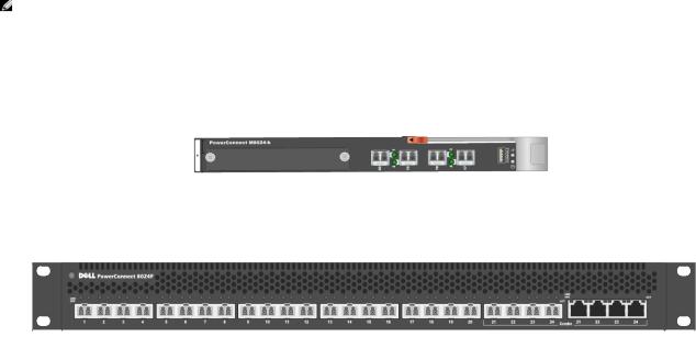
This document provides an easy to use guide for configuring FIP Snooping on the Dell PowerConnect™ M8024-k Blade Switch (Figure 1), and the PowerConnect™ 8024F (Figure 2).
Figure 1. Dell PowerConnect™ M8024-k Switch (10G Ethernet)
Figure 2. Dell PowerConnect™ 8024F (10G Ethernet)
Basic Terminology
FIP snooping
With FIP snooping enabled on the PowerConnect™ 8024 model switches, FIP logins, solicitations, and advertisements are monitored. In this monitoring or snooping process the switch gathers information pertaining to the ENode and FCF addresses. With this information the switch will then place filters that only allow access to ENode devices that have logged-in successfully. This enables the FCoE VLAN to deny all other traffic except this lossless FCoE storage traffic.
The filtering process also secures the end-to-end path between the ENode device and the FCF. The ENode will only be able to talk with the FCF in which it has logged into.
FIP snooping bridge (FSB)
With a switch configured to performing FIP snooping the industry term for this switch is FSB or FIP snooping bridge. It is performing FIP snooping as described in the previous term.
FCF
FCoE forwarders (FCFs) act as an Ethernet and FC switch combined. All typical termination functions that would occur on a FC switch occur on the FCF. FCF’s give VF_Ports and VE_Ports for their virtual FC interfaces.
6

Deploying FCoE (FIP Snooping) on Dell PowerConnect 10G Switches: M8024-k, 8024, and 8024F
PFC
Priority Flow Control (PFC), or Per-Priority Pause is defined in the IEEE 802.1Qbb standard. PFC is flow control based on priority settings and adds additional information to the standard pause frame. The additional fields added to the pause frame allow devices to pause traffic on a specific priority instead of pausing all traffic. (IEEE, 2009) Pause frames will be initiated by the FCF in most cases when its receive buffers are starting to reach a congested point. With PFC traffic is paused instead of dropped and retransmitted. This provides the lossless network behavior necessary for FC packets to be encapsulated and passed along the Ethernet paths.
NPIV
N-port identifier virtualization which enables multiple N-port fabric logins at the same time on the same physical FC link (Cisco Systems, Inc., 2011).This term is in reference to the Cisco Nexus 5000 series switches implementation of NPIV.
NPV
N-port virtualizer is a FC aggregation method which passes traffic through to end devices, while eliminating the need to use a domain ID for this device (Cisco Systems, Inc., 2011). This term is also in reference to configuration settings on the Cisco Nexus 5000 series switches.
VSAN
Virtual SAN is a logical partitioning of physical connections to provide for fabric or SAN separation.
Note: The Dell M1000e Server Chassis includes a console redirect feature that allows you to manage each PowerConnect M8024-k module from a single serial connection to the chassis. For more information about console redirect, see the Dell Blade Server CMC User's Guide
at http://support.dell.com/support/edocs/software/smdrac3/cmc/index.htm.
7
Deploying FCoE (FIP Snooping) on Dell PowerConnect 10G Switches: M8024-k, 8024, and 8024F
Configuration scenarios
The following sections will present very basic examples of deploying the 10G switches for FIP Snooping and will provide step-by-step explanations of the CLI commands as a guide. The GUI does not currently support configurations for FIP Snooping. Consult the table of contents above for a list of examples covered in this document.
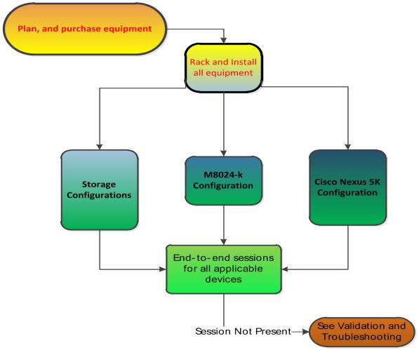
Figure 3. General overview of deployment
The following suggested configurations used to deploy this solution is done in a sequential order for reading but as Figure 3 represents this is more of a simultaneous process. There are dependencies that will be occuring during the configuration that will rely on other parts of the process. Storage configuration is not covered in any depth due to the possibility for various supported storage devices as part of the whole solution.
8

Deploying FCoE (FIP Snooping) on Dell PowerConnect 10G Switches: M8024-k, 8024, and 8024F
Important notes prior to deployment
 No Simple Mode
Each of the following scenarios in this document assume that the PowerConnect™ 8024 model switch being used is in normal Switch Mode (not Simple Mode) and is using firmware version 4.2.x.x or later.
NOTE: If Simple Mode is enabled it will need to be disabled prior to implementing the deployment covered in this document. FCoE is not supported with the PowerConnect 8024 model switches in Simple Mode. The CLI command in the example may be used for disabling Simple Mode, but please consult the User Guide for more information on specifics of Simple Mode.
Figure 4. Disabling simple mode
configure
no mode simple
_________________________________________________________________________________________
 Non-FIP-aware switches
If a Non-FIP-Aware switch is introduced anywhere in the data path FCoE will not be supported and can’t be expected to work as designed. The Dell PowerConnect M8024-k and 8024F are considered non- FIP-aware switches until they have the 4.2 or greater firmware installed. See updating firmware section for instructions on performing this update.
_________________________________________________________________________________________
 Stacking
Stacking is not recommended in an FCoE environment with the Dell PowerConnect 8024 Model Switches. If the switches are stacked the configuration should be changed to disable stacking. Please refer to the Dell PowerConnect 8024 4.2 firmware user’s guide for further details on disabling or changing stacking ports. If the configuration is used in this manner lossless Ethernet and reliability can not be guaranteed.
 Dell PowerConnect 4.2 or greater firmware on M8024-k or 8024F
As mentioned in the non-FIP-aware bullet the Dell PowerConnect Switches will not support FCoE or FIP snooping without 4.2 or greater firmware. See updating firmware section to perform this update.
________________________________________________________________________________________
9
Deploying FCoE (FIP Snooping) on Dell PowerConnect 10G Switches: M8024-k, 8024, and 8024F
Scenario 1: Deploying the Dell PowerConnect 8024 Series FSB in a Cisco 5000 Series Switch (NPIV) environment
This first example is a basic, single connection between devices example using the Dell PowerConnect M8024-k. This configuration is being shown for the purposes of simplification and potentially easing into the progression of a more in-depth setup. It is also easier to use a simple configuration such as this setup to aid in troubleshooting of the initial install. In a typical business environment most configurations will be scaled to include several connections between servers and storage. The scenarios following this one will show some of these larger configurations. Note that this configuration will also work in the rack server environment with Dell PowerConnect 8024F switch
Figure 5. Simple 1-link connection between devices
10

Deploying FCoE (FIP Snooping) on Dell PowerConnect 10G Switches: M8024-k, 8024, and 8024F
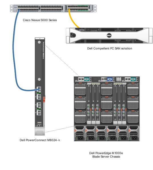
The flowchart in Figure 8 is a general overview of how the deployment will occur. This includes the basic planning that will need to take place in order for most of the steps in the rest of the document to fall into place.
Figure 6. General Overview of the whole configuration and planning procedure
11
Deploying FCoE (FIP Snooping) on Dell PowerConnect 10G Switches: M8024-k, 8024, and 8024F
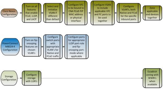
Figure 9 is a graphical representation of how many of the configuration pieces are considered parallel settings. Most of the configuration will depend heavily on configurations being completed in more than just one place.
Figure 7. Overview of parallel configuration
In many of the business environments where this configuration will be installed there will be different administrators for the different areas of the infrastructure. In other words there may be a LAN infrastructure administrator, a storage or SAN administrator, and potentially a server administrator. These different team members will have to work together for a successful deployment of all the involved parts. In an M1000e bladeserver environment it may be the server admin that deploys the blade servers, operatings systems, network adapter drivers, and very possibly configures the blade IOM networking switches. If different admins are involved as described these tasks can be done in parallel to enable a quicker deployment.
It is important to understand certain checks or validations along the way may rely on configurations being completed in a different part of the infrastructure.
12

Deploying FCoE (FIP Snooping) on Dell PowerConnect 10G Switches: M8024-k, 8024, and 8024F
Configuring the Dell PowerConnect M8024-k,8024, and 8024F for FIP Snooping
The Dell PowerConnect 8024 model switches will monitor FIP packets and will establish the proper filtering, and priorities for the FCoE traffic that is passed through the configured links. To see an example of the full configuration see Appendix-A - M8024-K Example.
Command-Line Interface Method
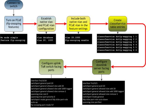
Figure 8. Example commands for Dell PowerConnect M8024-k (can be copied and pasted)
configure
no mode simple vlan database vlan 20,1000 exit
hostname "mySwitch" vlan database
vlan 20,1000 exit
feature fip-snooping vlan 20,1000 fip-snooping enable exit
interface out-of-band
ip address 192.168.10.1 255.255.255.0 192.168.10.254 exit
classofservice dot1p-mapping 1 1 classofservice dot1p-mapping 2 2 classofservice dot1p-mapping 3 3 classofservice dot1p-mapping 4 4 classofservice dot1p-mapping 5 5 classofservice dot1p-mapping 6 6 exit
interface Te1/0/1 switchport general pvid 20
switchport general allowed vlan add 20 switchport general allowed vlan add 1000 tagged switchport general allowed vlan remove 1 switchport mode general
lldp dcbx port-role auto-down spanning-tree portfast
exit
interface Te1/0/20 switchport general pvid 20
switchport general allowed vlan add 20 switchport general allowed vlan add 1000 tagged switchport general allowed vlan remove 1 spanning-tree cost 0
spanning-tree port-priority 0
switchport mode general lldp dcbx port-role auto-up fip-snooping port-mode fcf
exit
CAUTION: The “copy running-configuration startup-configuration” command should be issued after several impacting steps so that the switch will retain the configuration settings put into place on the next boot.
Routed VLAN’s can’t have FIP-snooping enabled. VLAN 1 may be set for routing and this must be changed in the VLAN database if it is going to be used as the native VLAN or PVID.
13
Deploying FCoE (FIP Snooping) on Dell PowerConnect 10G Switches: M8024-k, 8024, and 8024F
Step by Step explanation of CLI example
oConfigure – this brings the prompt into the configuration interface o no mode simple – puts switch into normal mode
o vlan database - moves down into the VLAN database interface
vlan 20 – add VLAN 20 to used for untagged traffic or as the native VLAN
vlan 1000 - add VLAN 1000 to the VLAN database, this will be the FCoE VLAN
exit – exit the current level of the interface configuration
o hostname “mySwitch” – set the hostname of the switch in this example “mySwitch”
o feature fip-snooping - this turns on the fip-snooping capability of the switch
ovlan 20,1000 – this moves the interface into vlan 20,1000
fip-snooping enable – this enables the fip-snooping capabilities on these particular VLAN’s. Both must be included for the initial TLV negotiation to establish the FCoE VLAN
exit – exit interface configuration
ointerface out-of-band – move into the interface out-of-band configuration interface
ip address 192.168.100.1 255.255.255.0 192.168.100.254 – this sets the out-of- band management interface IP address, subnet, and gateway for the switch
exit – exit the interface configuration
oclassofservice dot1p-mapping x x – establishes direct CoS mapping for the priorities (must be in place for certain CNA’s
ointerface te1/0/1 – this moves into the interface te1/0/1 configuration
switchport general pvid 20 – establishes the native VLAN as 20, you must remove VLAN 1 in order for this to function correctly
switchport general allowed vlan add 20 - adds VLAN 20 the trunk as an untagged VLAN
switchport general allowed vlan add 1000 tagged – this sets up a trunk with a tagged VLAN of 1000 (the FCoE VLAN), and includes the native VLAN as untagged if general mode is enabled.
switchport general allowed remove vlan 1 – this removes vlan 1 which would typically be the native vlan otherwise.
switchport mode general – this enables the port for general mode
lldp dcbx port-role auto-down – sets the DCBx port-role to be auto-down for an ENode connection
spanning-tree portfast – sets the ports to a portfast behavior since these are internalfacing server ports.
exit – exits the interface configuration
14

Deploying FCoE (FIP Snooping) on Dell PowerConnect 10G Switches: M8024-k, 8024, and 8024F
ointerface te1/0/20 – this moves into the interface te1/0/20 configuration
switchport general pvid 20 – establishes the native VLAN as 20, you must remove VLAN 1 in order for this to function correctly
switchport general allowed vlan add 20 - adds VLAN 20 the trunk as an untagged VLAN
switchport general allowed vlan add 1000 tagged - – this sets up a trunk with a tagged VLAN of 1000 (the FCoE VLAN), and includes the native VLAN as untagged if general mode is enabled.
switchport general allowed remove vlan 1 – this removes vlan 1 which would typically be the native vlan otherwise.
switchport mode general – this enables the port for mode general
spanning-tree cost 0 – sets spanning tree cost to 0
spanning-tree port-priority 0 – sets this ports priority to 0 so that it has the lowest spanning tree priority in case a loop is created elsewhere on the switch
lldp dcbx port-role auto-up – sets the DCBx port-role to be auto-up which dynamically sets the configuration-source for an FCF connection
fip-snooping port-mode fcf – enables the port for fip-snooping from an FCF connection
exit - exits the interface configuration
exit – exits from configuration mode
Critical steps: The “copy running-configuration startup-configuration” command should be issued after important steps so that the switch will retain the configuration settings when the switch is next rebooted or if a power loss occurs. It is also a good practice to copy a well-validated working configuration to a separate location such as the management station for the networks, and have a backup-configuration saved local to the switch.
Further explanation of key points:
•The spanning-tree settings in this example are established to keep the port from being potentially blocked by spanning-tree. This could occur because another cable is plugged into a port with a lower priority, causing a loop. When the uplink port is set to 0 it will have the lowest priority and therefore most likely not end up in a blocked state.
•A second key setting to note is “switchport general allowed vlan remove 1”. This command must be entered if you are choosing to use a different PVID or native VLAN. A port cannot have two native VLANs. In this example the configuration is set to use VLAN 20 since typically the recommendation is to have regular untagged traffic on a different VLAN other than just 1 for segregation of the network. In addition when the FCF sends information to the fip-snooping bridge (FSB) or M8024-k in this case, the M8024-k is receiving the initial information for negotiation on its untagged vlan (vlan 20 in this case). Once the initial negotiations have occurred properly the FCoE traffic will traverse the FCoE VLAN (in this case VLAN 1000).
•The last configuration line “fip-snooping port-mode fcf” is also key to this configuration. This line establishes where the FCF is attached to the switch. With this setting the port is configured to make Fibre Channel aware of the connection via this port to the forwarder. The previous line “lldp dcbx port-role auto-up“, is setting this port to be aware of DCBx TLV’s, he difference being the fip-snooping configuration line points to the port for using fip-snooping tohe FCF, and the lldp configuration points to the point for doing DCBx negotiations.
15
Deploying FCoE (FIP Snooping) on Dell PowerConnect 10G Switches: M8024-k, 8024, and 8024F
Figure 9. Configuration overview of Dell PowerConnect M8024-k
16

Deploying FCoE (FIP Snooping) on Dell PowerConnect 10G Switches: M8024-k, 8024, and 8024F
Configuring the Cisco 5000 series switch with firmware ver 5.x for a single connection from the Dell PowerConnect M8024-k or 8024()(F)
The CLI commands below are necessary for an un-configured Cisco 5020. The CLI will show additional lines that are either default or can’t be changed and are not added for this example. The CLI will also show the lines in a different order after they have been entered. Appendix-A Cisco Nexus 5548UP CLI example will have a copy of the full configuration for a 5548UP for reference.
Command-Line Interface Method
Figure 10. Sample CLI for Cisco Nexus 5020 (can be copied and pasted)
feature fcoe feature npiv feature telnet feature lacp feature lldp
system default switchport trunk mode auto
vlan 20 vlan 1000
fcoe vsan 2
vsan database vsan 2
vsan 2 interface vfc1 vsan 2 interface fc2/1
interface vfc1
bind interface Ethernet1/1 no shutdown
interface fc2/1
switchport trunk mode auto no shutdown
interface Ethernet1/1 switchport mode trunk
switchport trunk native vlan 20 switchport trunk allowed vlan 1000
zone name blade1 vsan 2 member interface fc2/1
member pwwn xx:xx:xx:xx:xx:xx:xx:xx
zoneset name set1 vsan 2 member blade1
zoneset activate name set1 vsan 2
17
Loading...