


 Loading...
Vostro 3681
Service Manual
1
Regulatory Model: D15S
Regulatory Type: D15S002
May 2020
Rev. A00

Notes, cautions, and warnings

 NOTE: A NOTE indicates important information that helps you make better use of your product.
 CAUTION: A CAUTION indicates either potential damage to hardware or loss of data and tells you how to avoid the problem.
 WARNING: A WARNING indicates a potential for property damage, personal injury, or death.
© 2020 Dell Inc. or its subsidiaries. All rights reserved. Dell, EMC, and other trademarks are trademarks of Dell Inc. or its subsidiaries. Other trademarks may be trademarks of their respective owners.

Contents
1 Working on your computer............................................................................................................ |
5 |
Safety instructions................................................................................................................................................................ |
5 |
Before working inside your computer........................................................................................................................... |
5 |
Safety precautions........................................................................................................................................................... |
6 |
Electrostatic discharge—ESD protection.................................................................................................................... |
6 |
ESD field service kit ........................................................................................................................................................ |
7 |
Transporting sensitive components............................................................................................................................... |
7 |
After working inside your computer.............................................................................................................................. |
8 |
2 Technology and components......................................................................................................... |
9 |
DDR4....................................................................................................................................................................................... |
9 |
USB features........................................................................................................................................................................ |
10 |
HDMI 1.4b.............................................................................................................................................................................. |
12 |
3 Disassembly and reassembly........................................................................................................ |
13 |
Recommended tools............................................................................................................................................................ |
13 |
Screw size list....................................................................................................................................................................... |
13 |
System board layout............................................................................................................................................................ |
14 |
Side cover.............................................................................................................................................................................. |
14 |
Removing the side cover............................................................................................................................................... |
14 |
Installing the side cover................................................................................................................................................. |
16 |
Bezel....................................................................................................................................................................................... |
17 |
Removing the front bezel.............................................................................................................................................. |
17 |
Installing the front bezel................................................................................................................................................ |
18 |
3.5 in. Hard disk drive.......................................................................................................................................................... |
19 |
Removing the 3.5-inch hard drive................................................................................................................................ |
19 |
Installing the 3.5-inch hard drive ................................................................................................................................. |
19 |
HDD/ODD Bracket.............................................................................................................................................................. |
20 |
Removing the HDD/ODD bracket............................................................................................................................... |
20 |
Installing the HDD/ODD bracket................................................................................................................................. |
22 |
Optical drive......................................................................................................................................................................... |
24 |
Removing the Optical Disk Drive................................................................................................................................. |
24 |
Installing the Optical Disk Drive.................................................................................................................................... |
26 |
Memory module................................................................................................................................................................... |
27 |
Removing the memory modules.................................................................................................................................. |
27 |
Installing the memory modules..................................................................................................................................... |
28 |
Graphics card....................................................................................................................................................................... |
29 |
Removing the graphics card........................................................................................................................................ |
29 |
Installing the graphics card........................................................................................................................................... |
30 |
Coin cell battery.................................................................................................................................................................... |
31 |
Removing the coin-cell battery..................................................................................................................................... |
31 |
Installing the coin-cell battery....................................................................................................................................... |
31 |
M.2 2230 Solid state drive................................................................................................................................................. |
32 |
Removing the 2230 solid-state drive.......................................................................................................................... |
32 |
Contents 3
Installing the 2230 solid-state drive............................................................................................................................ |
33 |
M.2 2280 Solid state drive................................................................................................................................................. |
34 |
Removing the 2280 solid-state drive.......................................................................................................................... |
34 |
Installing the 2280 solid-state drive............................................................................................................................ |
35 |
WLAN Card.......................................................................................................................................................................... |
36 |
Removing the WLAN card............................................................................................................................................ |
36 |
Installing the WLAN card.............................................................................................................................................. |
37 |
SD card................................................................................................................................................................................. |
39 |
Removing the media card reader................................................................................................................................ |
39 |
Installing the media card reader................................................................................................................................... |
39 |
Power supply unit................................................................................................................................................................ |
40 |
Removing the power-supply unit................................................................................................................................. |
40 |
Installing the power-supply unit................................................................................................................................... |
42 |
Heatsink assembly............................................................................................................................................................... |
45 |
Removing the heatsink assembly................................................................................................................................ |
45 |
Installing the heatsink assembly................................................................................................................................... |
46 |
Processor.............................................................................................................................................................................. |
47 |
Removing the processor............................................................................................................................................... |
47 |
Installing the processor................................................................................................................................................. |
49 |
System board....................................................................................................................................................................... |
50 |
Removing the system board........................................................................................................................................ |
50 |
Installing the system board........................................................................................................................................... |
53 |
4 Troubleshooting......................................................................................................................... |
57 |
Real-Time Clock (RTC Reset)........................................................................................................................................... |
57 |
System diagnostic lights..................................................................................................................................................... |
57 |
Diagnostic error messages................................................................................................................................................. |
58 |
System error messages....................................................................................................................................................... |
61 |
Recovering the operating system...................................................................................................................................... |
61 |
Flashing BIOS (USB key).................................................................................................................................................... |
62 |
Flashing the BIOS................................................................................................................................................................ |
62 |
WiFi power cycle................................................................................................................................................................. |
62 |
5 Getting help and contacting Dell.................................................................................................. |
63 |
4 Contents

1
Working on your computer
Safety instructions
Prerequisites
Use the following safety guidelines to protect your computer from potential damage and to ensure your personal safety. Unless otherwise noted, each procedure included in this document assumes that the following conditions exist:
•You have read the safety information that shipped with your computer.
•A component can be replaced or, if purchased separately, installed by performing the removal procedure in reverse order.
About this task
 NOTE: Disconnect all power sources before opening the computer cover or panels. After you finish working inside the computer, replace all covers, panels, and screws before connecting to the power source.
 WARNING: Before working inside your computer, read the safety information that shipped with your computer. For additional safety best practices information, see the Regulatory Compliance Homepage
 CAUTION: Many repairs may only be done by a certified service technician. You should only perform troubleshooting and simple repairs as authorized in your product documentation, or as directed by the online or telephone service and support team. Damage due to servicing that is not authorized by Dell is not covered by your warranty. Read and follow the safety instructions that came with the product.
 CAUTION: To avoid electrostatic discharge, ground yourself by using a wrist grounding strap or by periodically touching an unpainted metal surface at the same time as touching a connector on the back of the computer.
 CAUTION: Handle components and cards with care. Do not touch the components or contacts on a card. Hold a card by its edges or by its metal mounting bracket. Hold a component such as a processor by its edges, not by its pins.
 CAUTION: When you disconnect a cable, pull on its connector or on its pull-tab, not on the cable itself. Some cables have connectors with locking tabs; if you are disconnecting this type of cable, press in on the locking tabs before you disconnect the cable. As you pull connectors apart, keep them evenly aligned to avoid bending any connector pins. Also, before you connect a cable, ensure that both connectors are correctly oriented and aligned.

 NOTE: The color of your computer and certain components may appear differently than shown in this document.
 CAUTION: System will shut down if side covers are removed while the system is running. The system will not power on if the side cover is removed.
Before working inside your computer
About this task
To avoid damaging your computer, perform the following steps before you begin working inside the computer.
Steps
1.Ensure that you follow the Safety Instruction.
2.Ensure that your work surface is flat and clean to prevent the computer cover from being scratched.
3.Turn off your computer.
4.Disconnect all network cables from the computer.
Working on your computer |
5 |

 CAUTION: To disconnect a network cable, first unplug the cable from your computer and then unplug the cable from the network device.
5.Disconnect your computer and all attached devices from their electrical outlets.
6.Press and hold the power button while the computer is unplugged to ground the system board.
 NOTE: To avoid electrostatic discharge, ground yourself by using a wrist grounding strap or by periodically touching an unpainted metal surface at the same time as touching a connector on the back of the computer.
Safety precautions
The safety precautions chapter details the primary steps to be taken before performing any disassembly instructions.
Observe the following safety precautions before you perform any installation or break/fix procedures involving disassembly or reassembly:
•Turn off the system and all attached peripherals.
•Disconnect the system and all attached peripherals from AC power.
•Disconnect all network cables, telephone, and telecommunications lines from the system.
•Use an ESD field service kit when working inside any tabletnotebookdesktop to avoid electrostatic discharge (ESD) damage.
•After removing any system component, carefully place the removed component on an anti-static mat.
•Wear shoes with non-conductive rubber soles to reduce the chance of getting electrocuted.
Standby power
Dell products with standby power must be unplugged before you open the case. Systems that incorporate standby power are essentially powered while turned off. The internal power enables the system to be remotely turned on (wake on LAN) and suspended into a sleep mode and has other advanced power management features.
Unplugging, pressing and holding the power button for 15 seconds should discharge residual power in the system board.
Bonding
Bonding is a method for connecting two or more grounding conductors to the same electrical potential. This is done through the use of a field service electrostatic discharge (ESD) kit. When connecting a bonding wire, ensure that it is connected to bare metal and never to a painted or non-metal surface. The wrist strap should be secure and in full contact with your skin, and ensure that you remove all jewelry such as watches, bracelets, or rings prior to bonding yourself and the equipment.
Electrostatic discharge—ESD protection
ESD is a major concern when you handle electronic components, especially sensitive components such as expansion cards, processors, memory DIMMs, and system boards. Very slight charges can damage circuits in ways that may not be obvious, such as intermittent problems or a shortened product life span. As the industry pushes for lower power requirements and increased density, ESD protection is an increasing concern.
Due to the increased density of semiconductors used in recent Dell products, the sensitivity to static damage is now higher than in previous Dell products. For this reason, some previously approved methods of handling parts are no longer applicable.
Two recognized types of ESD damage are catastrophic and intermittent failures.
•Catastrophic – Catastrophic failures represent approximately 20 percent of ESD-related failures. The damage causes an immediate and complete loss of device functionality. An example of catastrophic failure is a memory DIMM that has received a static shock and immediately generates a "No POST/No Video" symptom with a beep code emitted for missing or nonfunctional memory.
•Intermittent – Intermittent failures represent approximately 80 percent of ESD-related failures. The high rate of intermittent failures means that most of the time when damage occurs, it is not immediately recognizable. The DIMM receives a static shock, but the tracing is merely weakened and does not immediately produce outward symptoms related to the damage. The weakened trace may take weeks or months to melt, and in the meantime may cause degradation of memory integrity, intermittent memory errors, etc.
The more difficult type of damage to recognize and troubleshoot is the intermittent (also called latent or "walking wounded") failure.
Perform the following steps to prevent ESD damage:
•Use a wired ESD wrist strap that is properly grounded. The use of wireless anti-static straps is no longer allowed; they do not provide adequate protection. Touching the chassis before handling parts does not ensure adequate ESD protection on parts with increased sensitivity to ESD damage.
•Handle all static-sensitive components in a static-safe area. If possible, use anti-static floor pads and workbench pads.
6 Working on your computer
•When unpacking a static-sensitive component from its shipping carton, do not remove the component from the anti-static packing material until you are ready to install the component. Before unwrapping the anti-static packaging, ensure that you discharge static electricity from your body.
•Before transporting a static-sensitive component, place it in an anti-static container or packaging.
ESD field service kit
The unmonitored Field Service kit is the most commonly used service kit. Each Field Service kit includes three main components: antistatic mat, wrist strap, and bonding wire.
Components of an ESD field service kit
The components of an ESD field service kit are:
•Anti-Static Mat – The anti-static mat is dissipative and parts can be placed on it during service procedures. When using an antistatic mat, your wrist strap should be snug and the bonding wire should be connected to the mat and to any bare metal on the system being worked on. Once deployed properly, service parts can be removed from the ESD bag and placed directly on the mat. ESDsensitive items are safe in your hand, on the ESD mat, in the system, or inside a bag.
•Wrist Strap and Bonding Wire – The wrist strap and bonding wire can be either directly connected between your wrist and bare metal on the hardware if the ESD mat is not required, or connected to the anti-static mat to protect hardware that is temporarily placed on the mat. The physical connection of the wrist strap and bonding wire between your skin, the ESD mat, and the hardware is known as bonding. Use only Field Service kits with a wrist strap, mat, and bonding wire. Never use wireless wrist straps. Always be aware that the internal wires of a wrist strap are prone to damage from normal wear and tear, and must be checked regularly with a wrist strap tester in order to avoid accidental ESD hardware damage. It is recommended to test the wrist strap and bonding wire at least once per week.
•ESD Wrist Strap Tester – The wires inside of an ESD strap are prone to damage over time. When using an unmonitored kit, it is a best practice to regularly test the strap prior to each service call, and at a minimum, test once per week. A wrist strap tester is the best method for doing this test. If you do not have your own wrist strap tester, check with your regional office to find out if they have one. To perform the test, plug the wrist-strap's bonding-wire into the tester while it is strapped to your wrist and push the button to test. A green LED is lit if the test is successful; a red LED is lit and an alarm sounds if the test fails.
•Insulator Elements – It is critical to keep ESD sensitive devices, such as plastic heat sink casings, away from internal parts that are insulators and often highly charged.
•Working Environment – Before deploying the ESD Field Service kit, assess the situation at the customer location. For example, deploying the kit for a server environment is different than for a desktop or portable environment. Servers are typically installed in a rack within a data center; desktops or portables are typically placed on office desks or cubicles. Always look for a large open flat work area that is free of clutter and large enough to deploy the ESD kit with additional space to accommodate the type of system that is being repaired. The workspace should also be free of insulators that can cause an ESD event. On the work area, insulators such as Styrofoam and other plastics should always be moved at least 12 inches or 30 centimeters away from sensitive parts before physically handling any hardware components
•ESD Packaging – All ESD-sensitive devices must be shipped and received in static-safe packaging. Metal, static-shielded bags are preferred. However, you should always return the damaged part using the same ESD bag and packaging that the new part arrived in. The ESD bag should be folded over and taped shut and all the same foam packing material should be used in the original box that the new part arrived in. ESD-sensitive devices should be removed from packaging only at an ESD-protected work surface, and parts should never be placed on top of the ESD bag because only the inside of the bag is shielded. Always place parts in your hand, on the ESD mat, in the system, or inside an anti-static bag.
•Transporting Sensitive Components – When transporting ESD sensitive components such as replacement parts or parts to be returned to Dell, it is critical to place these parts in anti-static bags for safe transport.
ESD protection summary
It is recommended that all field service technicians use the traditional wired ESD grounding wrist strap and protective anti-static mat at all times when servicing Dell products. In addition, it is critical that technicians keep sensitive parts separate from all insulator parts while performing service and that they use anti-static bags for transporting sensitive components.
Transporting sensitive components
When transporting ESD sensitive components such as replacement parts or parts to be returned to Dell, it is critical to place these parts in anti-static bags for safe transport.
Lifting equipment
Adhere to the following guidelines when lifting heavy weight equipment:
Working on your computer |
7 |

 CAUTION: Do not lift greater than 50 pounds. Always obtain additional resources or use a mechanical lifting device.
1.Get a firm balanced footing. Keep your feet apart for a stable base, and point your toes out.
2.Tighten stomach muscles. Abdominal muscles support your spine when you lift, offsetting the force of the load.
3.Lift with your legs, not your back.
4.Keep the load close. The closer it is to your spine, the less force it exerts on your back.
5.Keep your back upright, whether lifting or setting down the load. Do not add the weight of your body to the load. Avoid twisting your body and back.
6.Follow the same techniques in reverse to set the load down.
After working inside your computer
About this task
After you complete any replacement procedure, ensure that you connect any external devices, cards, and cables before turning on your computer.
Steps
1.Connect any telephone or network cables to your computer.
 CAUTION: To connect a network cable, first plug the cable into the network device and then plug it into the computer.
2.Connect your computer and all attached devices to their electrical outlets.
3.Turn on your computer.
4.If required, verify that the computer works correctly by running ePSA diagnostics.
8 Working on your computer
2
Technology and components
This chapter details the technology and components available in the system.
DDR4
DDR4 (double data rate fourth generation) memory is a higher-speed successor to the DDR2 and DDR3 technologies and allows up to 512 GB in capacity, compared to the DDR3's maximum of 128 GB per DIMM. DDR4 synchronous dynamic random-access memory is keyed differently from both SDRAM and DDR to prevent the user from installing the wrong type of memory into the system.
DDR4 needs 20 percent less or just 1.2 volts, compared to DDR3 which requires 1.5 volts of electrical power to operate. DDR4 also supports a new, deep power-down mode that allows the host device to go into standby without needing to refresh its memory. Deep power-down mode is expected to reduce standby power consumption by 40 to 50 percent.
DDR4 Details
There are subtle differences between DDR3 and DDR4 memory modules, as listed below.
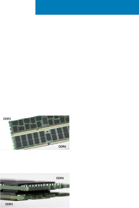
Key notch difference
The key notch on a DDR4 module is in a different location from the key notch on a DDR3 module. Both notches are on the insertion edge but the notch location on the DDR4 is slightly different, to prevent the module from being installed into an incompatible board or platform.
Figure 1. Notch difference
Increased thickness
DDR4 modules are slightly thicker than DDR3, to accommodate more signal layers.
Figure 2. Thickness difference
Curved edge
DDR4 modules feature a curved edge to help with insertion and alleviate stress on the PCB during memory installation.
Technology and components |
9 |
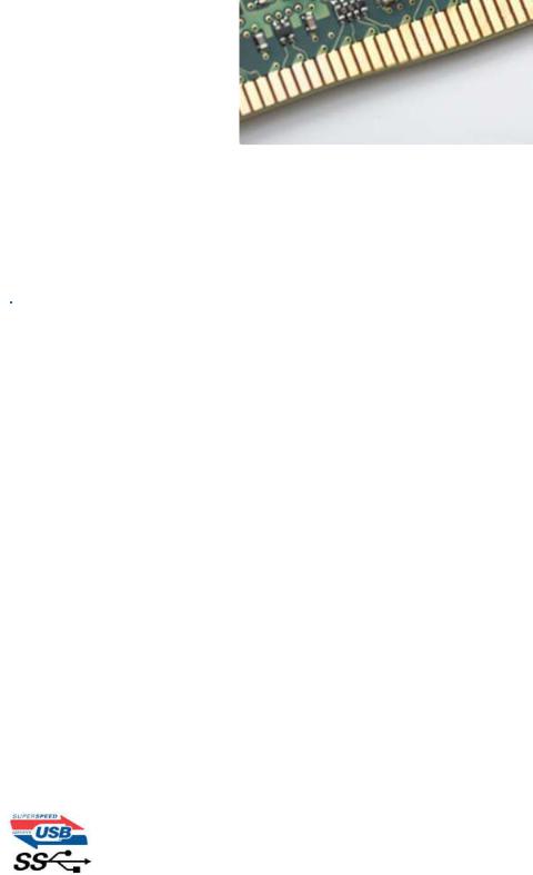
Figure 3. Curved edge
Memory Errors
Memory errors on the system display 2,3 failure code. If all memory fails, the LCD does not turn on. Troubleshoot for possible memory failure by trying known good memory modules in the memory connectors on the bottom of the system or under the keyboard, as in some portable systems.

 NOTE: The DDR4 memory is imbedded in board and not a replaceable DIMM as shown and referred.
USB features
Universal Serial Bus, or USB, was introduced in 1996. It dramatically simplified the connection between host computers and peripheral devices like mice, keyboards, external drivers, and printers.
Table 1. USB evolution
Type |
Data Transfer Rate |
Category |
Introduction Year |
|
|
|
|
|
|
|
|
USB 2.0 |
480 Mbps |
High Speed |
2000 |
|
|
|
|
USB 3.2 Gen 1 |
5 Gbps |
SuperSpeed |
2010 |
|
|
|
|
USB 3.2 Gen 1 (SuperSpeed USB)
For years, the USB 2.0 has been firmly entrenched as the de facto interface standard in the PC world with about 6 billion devices sold, and yet the need for more speed grows by ever faster computing hardware and ever greater bandwidth demands. The USB 3.1 Gen 2 finally has the answer to the consumers' demands with a theoretically 10 times faster than its predecessor. In a nutshell, USB 3.2 Gen 1 features are as follows:
•Higher transfer rates (up to 5 Gbps)
•Increased maximum bus power and increased device current draw to better accommodate power-hungry devices
•New power management features
•Full-duplex data transfers and support for new transfer types
•Backward USB 2.0 compatibility
•New connectors and cable
The topics below cover some of the most commonly asked questions regarding USB 3.2 Gen 1.
Speed
Currently, there are 3 speed modes defined by the latest USB 3.2 Gen 1/USB 3.2 Gen 1 and USB 3.2 Gen 2x2 specification. They are Super-Speed, Hi-Speed and Full-Speed. The new SuperSpeed mode has a transfer rate of 4.8 Gbps. While the specification retains HiSpeed, and Full-Speed USB mode, commonly known as USB 2.0 and 1.1 respectively, the slower modes still operate at 480 Mbps and 12 Mbps respectively and are kept to maintain backward compatibility.
USB 3.2 Gen 1 achieves the much higher performance by the technical changes below:
10 Technology and components
•An additional physical bus that is added in parallel with the existing USB 2.0 bus (refer to the picture below).
•USB 2.0 previously had four wires (power, ground, and a pair for differential data); USB 3.0/USB 3.1 Gen 1 adds four more for two pairs of differential signals (receive and transmit) for a combined total of eight connections in the connectors and cabling.
•USB 3.2 Gen 1 utilizes the bidirectional data interface, rather than USB 2.0's half-duplex arrangement. This gives a 10-fold increase in theoretical bandwidth.
With today's ever increasing demands placed on data transfers with high-definition video content, terabyte storage devices, high megapixel count digital cameras etc., USB 2.0 may not be fast enough. Furthermore, no USB 2.0 connection could ever come close to the 480Mbps theoretical maximum throughput, making data transfer at around 320 Mbps (40 MB/s) — the actual real-world maximum. Similarly, USB 3.0/USB 3.1 Gen 1 connections will never achieve 4.8Gbps. We will likely see a real-world maximum rate of 400MB/s with overheads. At this speed, USB 3.0/USB 3.1 Gen 1 is a 10x improvement over USB 2.0.
Applications
USB 3.2 Gen 1 opens up the laneways and provides more headroom for devices to deliver a better overall experience. Where USB video was barely tolerable previously (both from a maximum resolution, latency, and video compression perspective), it's easy to imagine that with 5-10 times the bandwidth available, USB video solutions should work that much better. Single-link DVI requires almost 2 Gbps throughput. Where 480Mbps was limiting, 5Gbps is more than promising. With its promised 4.8Gbps speed, the standard will find its way into some products that previously weren't USB territory, like external RAID storage systems.
Listed below are some of the available SuperSpeed USB 3.2 Gen 1 products:
•External Desktop USB Hard Drives
•Portable USB Hard Drives
•USB Drive Docks & Adapters
•USB Flash Drives & Readers
•USB Solid-state Drives
•USB RAIDs
•Optical Media Drives
•Multimedia Devices
•Networking
•USB Adapter Cards & Hubs
Compatibility
The good news is that USB 3.2 Gen 1 has been carefully planned from the start to peacefully co-exist with USB 2.0. First of all, while USB 3.2 Gen 1 specifies new physical connections and thus new cables to take advantage of the higher speed capability of the new protocol, the connector itself remains the same rectangular shape with the four USB 2.0 contacts in the exact same location as before. Five new connections to carry receive and transmitted data independently are present on USB 3.2 Gen 1 cables and only come into contact when connected to a proper SuperSpeed USB connection.
Technology and components |
11 |
HDMI 1.4b
This topic explains the HDMI 1.4b and its features along with the advantages.
HDMI (High-Definition Multimedia Interface) is an industry-supported, uncompressed, all-digital audio/video interface. HDMI provides an interface between any compatible digital audio/video source, such as a DVD player, or A/V receiver and a compatible digital audio and/or video monitor, such as a digital TV (DTV). The intended applications for HDMI TVs, and DVD players. The primary advantage is cable reduction and content protection provisions. HDMI supports standard, enhanced, or high-definition video, plus multichannel digital audio on a single cable.
HDMI 1.4b Features
•HDMI Ethernet Channel - Adds high-speed networking to an HDMI link, allowing users to take full advantage of their IP-enabled devices without a separate Ethernet cable
•Audio Return Channel - Allows an HDMI-connected TV with a built-in tuner to send audio data "upstream" to a surround audio system, eliminating the need for a separate audio cable
•3D - Defines input/output protocols for major 3D video formats, paving the way for true 3D gaming and 3D home theater applications
•Content Type - Real-time signaling of content types between display and source devices, enabling a TV to optimize picture settings based on content type
•Additional Color Spaces - Adds support for additional color models used in digital photography and computer graphics
•4K Support - Enables video resolutions far beyond 1080p, supporting next-generation displays that will rival the Digital Cinema systems used in many commercial movie theaters
•HDMI Micro Connector - A new, smaller connector for phones and other portable devices, supporting video resolutions up to 1080p
•Automotive Connection System - New cables and connectors for automotive video systems, designed to meet the unique demands of the motoring environment while delivering true HD quality
Advantages of HDMI
•Quality HDMI transfers uncompressed digital audio and video for the highest, crispest image quality.
•Low -cost HDMI provides the quality and functionality of a digital interface while also supporting uncompressed video formats in a simple, cost-effective manner
•Audio HDMI supports multiple audio formats from standard stereo to multichannel surround sound
•HDMI combines video and multichannel audio into a single cable, eliminating the cost, complexity, and confusion of multiple cables currently used in A/V systems
•HDMI supports communication between the video source (such as a DVD player) and the DTV, enabling new functionality
12 Technology and components

3
Disassembly and reassembly
Recommended tools
The procedures in this document require the following tools:
•Small flat blade screwdriver
•Phillips # 1 screwdriver
•Small plastic scribe
•Hex screwdriver
Screw size list
Table 2. Screw size list
|
M2x3 |
M2X4 |
6-32X1/4" |
Component |
|
|
|
|
|
|
|
|
|
|
|
Hard drive |
|
|
1 |
|
|
|
|
HDD/ODD bracket |
|
|
1 |
|
|
|
|
Optical drive |
1 |
|
|
|
|
|
|
WLAN |
1 |
|
|
|
|
|
|
SSD card |
1 |
|
|
|
|
|
|
Power supply unit (PSU) |
|
|
3 |
|
|
|
|
IO module |
|
|
6 |
|
|
|
|
Internal antenna |
|
|
|
|
|
|
|
Card reader |
|
|
2 |
|
|
|
|
System board |
|
1 |
8 |
|
|
|
|
Front IO bracket |
|
|
1 |
|
|
|
|
Disassembly and reassembly |
13 |
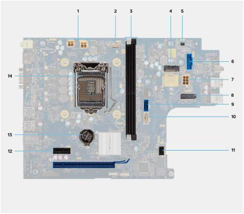
System board layout
This section illustrates the system board and calls out the ports and connectors.
1.ATX Power connector (ATX_CPU1 and ATX_CPU2)
2.CPU fan connector (Fan_CPU)
3.Memory-module slots (DIMM1, DIMM2)
4.M.2 2230/2280 connector (for SSD)
5.Power switch connector (PWR_SW)
6.SD card reader connector
7.ATX Power connector(ATX_SYS)
8.M.2 2230 connector (for WLAN card)
9.SATA 3.0 data connector (SATA0)
10.SATA 3.0 data connector (SATA3)
11.SATA 3.0 power connector (SATA_PWR)
12.PCIe expansion slots (SLOT1: PCIe x1, SLOT2: PCIe x16)
13.Coin-cell battery
14.CPU socket
Side cover
Removing the side cover
Prerequisites
1. Follow the procedure in Before working inside your computer.
14 Disassembly and reassembly
About this task
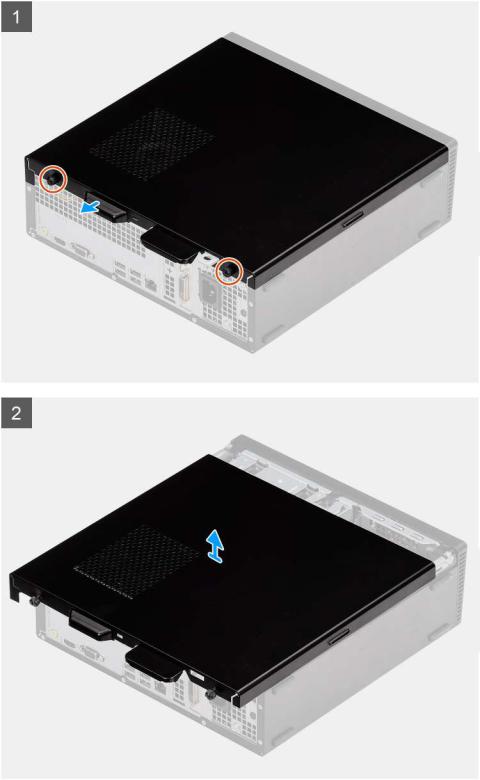
The following images indicate the location of the side cover and provide a visual representation of the removal procedure:
Steps
1.Loosen the two captive screws and slide the side cover to release it from the chassis.
2.Lift the side cover, off the chassis.
Disassembly and reassembly |
15 |
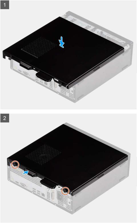
Installing the side cover
Prerequisites
If you are replacing a component, remove the existing component before performing the installation procedure:
About this task
The following images indicate the location of the side cover and provide a visual representation of the installation procedure:
16 Disassembly and reassembly
Steps
1.Align the tabs on the side cover with the slots and replace the side cover on the chassis.
2.Slide the side cover towards the front of the unit and tighten the two cap screws to secure the side cover to the chassis.
Next steps
1. Follow the procedure in After working inside your computer.
Bezel
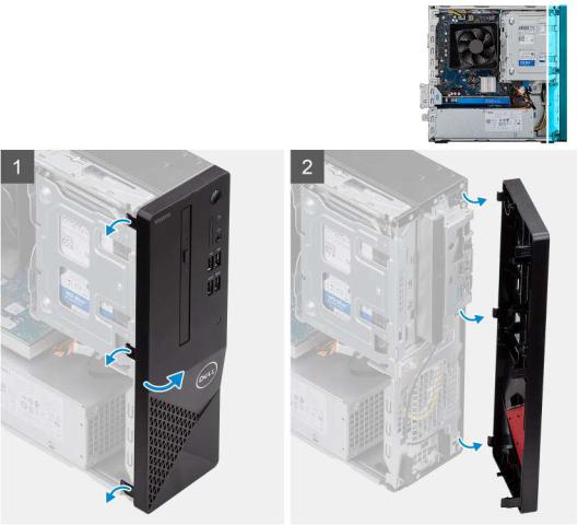
Removing the front bezel
Prerequisites
1.Follow the procedure in Before working inside your computer.
2.Remove the side cover.
3.Place the computer in an upright position.
About this task
The following images indicate the location of the front bezel and provide a visual representation of the removal procedure:
Steps
1.Gently pry and release the front bezel tabs sequentially from the top.
2.Rotate the front cover outward from the chassis.
Disassembly and reassembly |
17 |
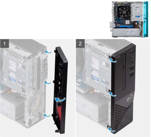
Installing the front bezel
Prerequisites
If you are replacing a component, remove the existing component before performing the installation procedure.
•Place the computer in an upright position.
About this task
The following images indicate the location of the front bezel and provide a visual representation of the installation procedure:
Steps
1.Align the tabs on the bezel with the slots on the chassis.
2.Rotate the front cover towards the chassis and snap it into place.
Next steps
1.Install the side cover.
2.Follow the procedure in After working inside your computer.
18 Disassembly and reassembly

3.5 in. Hard disk drive
Removing the 3.5-inch hard drive
Prerequisites
1.Follow the procedure in Before working inside your computer.
2.Remove the side cover.
About this task
The following images indicate the location of the 3.5-inch hard drive and provides a visual representation of the removal procedure:
Steps
1.Disconnect the data and power SATA cables from the hard drive and remove the two #6-32 screws.
2.Lift and remove the 3.5 inch hard drive from the bracket.
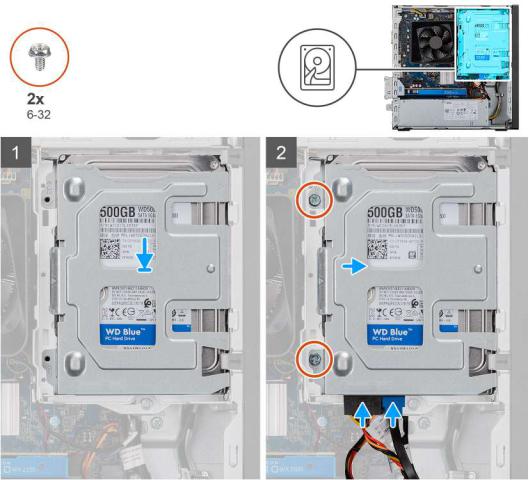
Installing the 3.5-inch hard drive
Prerequisites
If you are replacing a component, remove the existing component before performing the installation procedure.
Disassembly and reassembly |
19 |
About this task
The following images indicate the location of the 3.5-inch hard drive and provides a visual representation of the installation procedure:
Steps
1.Place the hard drive into the hard-drive bracket and align the tabs on the bracket with the slots on the hard drive.
2.Secure the two #6-32 screws securing the 3.5 in. hard drive to the bracket.
Next steps
1.Install the side cover.
2.Follow the procedure in After working inside your computer.
HDD/ODD Bracket
Removing the HDD/ODD bracket
Prerequisites
1.Follow the procedure in Before working inside your computer.
2.Remove the side cover.
3.Remove the 3.5 in. HDD.
About this task
The following image indicates the location of the HDD/ODD bracket and provides a visual representation of the removal procedure.
20 Disassembly and reassembly
Loading...