


 Loading...
Dell EMC Networking N-Series
N2200 Switches
Getting Started Guide
Version 6.6.1
Regulatory Model: E41W

Notes and Cautions
NOTE: A NOTE indicates important information that helps you make better use of your computer.
 CAUTION: A CAUTION indicates potential damage to hardware or loss of data if instructions are not followed.
____________
Information in this publication is subject to change without notice. Copyright © 2019 Dell EMC Inc.All rights reserved.
ReproductionofthesematerialsinanymannerwhatsoeverwithoutthewrittenpermissionofDellInc. is strictly forbidden.
This product is protected by U.S. and international copyright and intellectual property laws. Dell EMC™ and the Dell EMC logo are trademarks of Dell EMC Inc. in the United States and/or other jurisdictions. All other marks and names mentioned herein may be trademarks of their respective companies.
Marketing Models: N2224X-ON, N2224PX-ON, N2248X-ON, N2248PX-ON
Regulatory Model: E41W
2019 - 11 |
Rev. A00 |

Contents
1Introduction . . . . . . . . . . . . . . . . . . . . . . . . 3
2N2200 Series Overview . . . . . . . . . . . . . . . 3
3N2200 Series Hardware Overview . . . . . . . 4
Dell EMC Networking N2200-ON Series Switch Hardware 4
4 N2200 Installation . . . . . . . . . . . . . . . . . . |
13 |
Site Preparation . . . . . . . . . . . . . . . . . . . . . |
13 |
Unpacking the N2200 Switch . . . . . . . . . . . . . . |
14 |
Rack Mounting a N2200 Switch . . . . . . . . . . . . . |
14 |
Stacking Multiple N2200 Switches . . . . . . . . . . . |
16 |
5 Starting and Configuring the N2200 Switch 18
Connecting a N2200 Switch to a Terminal . . . . . . . |
19 |
Connecting a N2200 Switch to a Power Source . . . . |
20 |
Booting the N2200 Switch . . . . . . . . . . . . . . . . |
21 |
Performing the N2200 Initial Configuration . . . . . . . |
21 |
Contents 1

6 Specifications . . . . . . . . . . . . . . . . . . . . . 28
Chassis Physical Design. . . . . . . . . . . . . . . . . 28
7 Dell EMC Support . . . . . . . . . . . . . . . . . . . 32
2 Contents

Introduction
This document provides basic information about the Dell® EMC™ Networking N2200 Series switches, including how to install a switch and perform the initial configuration. For information about how to configure and monitor switch features, see the User’s Configuration Guide, which is available on the Dell Support website at dell.com/support/manuals, for the latest updates on documentation and firmware.
This document contains the following sections:
•N2200 Series Overview
•N2200 Series Hardware Overview
•N2200 Installation
•Starting and Configuring the N2200 Switch
NOTE: Switch administrators are strongly advised to maintain Dell EMC Networking switches on the latest version of the Dell EMC Networking Operating System (DNOS). Dell EMC Networking continually improves the features and functions of DNOS based on feedback from you, the customer. For critical infrastructure, prestaging of the new release into a noncritical portion of the network is recommended to verify network configuration and operation with the new DNOS version.
N2200 Series Overview
The Dell EMC Networking N2200-ON switches are stackable Layer 2/3 1 Gigabit stackable Ethernet switches and include the following models:
•Dell EMC Networking N2200X-ON
•Dell EMC Networking N2224PX-ON
•Dell EMC Networking N2224X-ON
•Dell EMC Networking N2248PX-ON
•Dell EMC Networking N2248X-ON
3

N2200 Series Hardware Overview
Dell EMC Networking N2200-ON Series Switch Hardware
This section contains information about device characteristics and modular hardware configurations for the Dell EMC Networking N2200 Series switches.
N2200-ON Series Front Panel
The Dell EMC Networking N2224X-ON/N2224PX-ON/N2248X- ON/N2248PX-ON switch front panels include the following features:
•24 or 48 RJ-45 10/100/1000/2500BASE-T ports
•Four SFP28 10G/25GBASE-X ports
•Two QSFP 40G stacking ports
•RJ-45 and Type-B micro USB 3.0 console ports
•Reset button
•Port and system LEDs
•Stack Master LED and Stack Number Display
•Type-A USB 3.0 port for storage
•Out-of-band Ethernet interface
The following images show a representative front panel of the Dell EMC Networking switch.
4
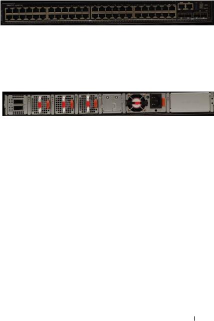
Figure 1-1. Dell EMC Networking N2248PX-ON Switch (Front Panel)
N2200-ON Series Rear Panel
The Dell EMC Networking N2200-ON Series back panel has two 40G QSFP stacking ports in the rear. It also has two slots for power supplies, and two (N2224X-ON/N2224PX-ON) or three (N2248X-ON/N2248PX-ON) hot-swap fan trays.
Figure 1-2. Dell EMC Networking N2248PX Switch (Rear Panel)
N2200X-ON Series Switch Ports
The Dell EMC Networking N2200X-ON Series front panel provides 24 or 48 10/100/1000/2500BASE-T Ethernet RJ-45 ports that support auto-negotiation for speed, flow control, and duplex. Dell EMC Networking N2200X-ON Series switch front panel 2.5G ports operate in full-duplex at all speeds or half-duplex at 10/100 Mbps speeds. The Dell EMC Networking N2200X-ON Series switch models support four 10G/25G SFP28 ports and two 40G QSFP stacking ports. Dell-qualified transceivers are sold separately.
The front-panel switch ports have the following characteristics:
•The switch automatically detects the difference between crossed and straight-through cables on RJ-45 ports and automatically chooses the MDI or MDIX configuration to match the other end.
•The 10/100/1000/2500BASE-T Ethernet RJ-45 ports support full-duplex mode 10/100/1000/2500 Mbps speeds or half-duplex 10/100 Mbps speeds on standard Category 5 UTP cable. 2500BASE-T operation requires the use of auto-negotiation.
•SFP28 ports support Dell-qualified transceivers utilizing 25GBASE-SR, 25GBASE-LR, 25GBASE-CR, 25GBASE-CR-S or 25GBASE-ER technologies. SFP28 ports support SFP+ fiber transceivers and SFP+ copper twin-ax or DAC technology operating at 10G speeds in full-duplex
5

mode. All four SFP28 ports must be configured to operate at the same speed. 25GBASE-CR and 10G-BASE-CR modes (copper twin-ax or DAC cables) require the use of auto-negotiation.
•The default behavior is to log a message and generate an SNMP trap on insertion or removal of a transceiver that is not qualified by Dell. The message and trap can be suppressed by using the service unsupportedtransceiver command.
On the N2224X-ON/N2224PX-ON switches, ports 1-12 may be configured to support 10M/100M half-duplex.
On the N2248X-ON switches, ports 5-36 may be configured to support 10M/100M half-duplex.
N2200-ON SFP28 ports may be configured to operate using SFP+ transceivers using the speed 10000 command for fiber media or the speed auto 10000 command for copper media. All four SFP28 ports must be configured to operate at the same speed. A mix of SFP+ and SFP28 transceivers or speeds is not supported. The switch UI does not enforce this restriction.
N2200-ON Series Console Port
The console port provides serial communication capabilities, which allows communication using RS-232 protocol. The serial port provides a direct connection to the switch and allows access to the CLI from a console terminal connected to the port through the provided serial cable (with RJ-45 YOST to female DB-9 connectors). The console port is separately configurable and can be run as an asynchronous link from 1200 baud to 115,200 baud. The Dell CLI only supports changing the speed. The defaults are 115,200 baud rate, 8 data bits, no parity, 1 stop bit, no flow control.
6

Figure 1-3. Dell EMC Networking N2248 Console Port
A separate USB micro type B port is also available for console access to the CPU CLI. RS-232 emulation over USB is supported on this port. A driver may need to be installed to support the RS-232 emulation. Only one of the console ports may be used at a time.
N2200-ON Series USB Port
The Type-A, female USB port supports a USB 3.0-compliant flash memory drive. The Dell EMC Networking N-Series switch can read or write to a flash drive with a single partition formatted as FAT-32. Use a USB flash drive to copy switch configuration files and images between the USB flash drive and the switch. The USB flash drive may be used to move and copy configuration files and images to other switches in the network. The system does not support the deletion of files on USB flash drives. The USB port does not support any other type of USB device.
N2200-ON Series Reset Button
The reset button is accessed through the pinhole and enables performing a hard or soft reset of the switch. To reset the switch, insert an unbent paper clip or similar tool into the pinhole for four seconds. When the switch completes the boot process after the reset, it resumes operation with the most recently saved configuration. Any changes made to the running configuration that were not saved to the startup configuration prior to the reset are lost.
7

To clear the configuration and reset the switch, press the reset button for at least eight seconds. The saved configuration is cleared and the switch reboots. The switch then starts the autoconfiguration process.
N2200-ON Series Port and System LEDs
The front panel contains light emitting diodes (LEDs) that indicate the status of system temperature, port links, power supplies, fans, stacking, and the overall system status. A locator beacon capability is also present on the system LEDs. See N2200-ON Series LED Definitions for more information.
N2200-ON Series Stack Master LED and Stack Number Display
When a switch within a stack is the master unit, the stack master LED is solid green. If the stack master LED is off, the stack member is not the master unit. The stack number LCD displays the unit number for the stack member. If a switch is not part of a stack (in other words, it is a stack of one switch), the stack master LED is illuminated, and the unit number is displayed.
N2200-ON Series Power Supplies
The Dell EMC Networking N2224X-ON/N2248X-ON switches have a fieldreplaceable 550W power supply (DS-550 AC). An additional field-replaceable power supply may be added to support redundancy.
The Dell EMC Networking N2224PX-ON switches have a field-replaceable 1050-watt power supply (DPS-1050 AC) feeding up to 16x30W PoE and 2x60W devices at full power (712W). The Dell EMC Networking N2248PXON switches have an internal 1050W power supply (DPS-1050 AC) feeding up to 16x30W PoE devices and 1Xx60W at full power (624W).
In both PoE models, additional field replaceable 1050W, 1300W, or 1600W power supplies are available to support redundancy or to supply full front panel demand.
Table 1-1 shows power budget data.
Table 1-1. Dell EMC Networking N2200PX-ON Series PoE Power Budget Limit
|
|
One PSU |
Two PSUs (2x1050W) |
|
|
|
|
|
|
Model Name |
PoE Power |
Power |
PoE Power |
Power |
|
Budget |
Turn-on Limitation |
Budget |
Turn-on Limitation |
|
|
|
|
|
8
Table 1-1. Dell EMC Networking N2200PX-ON Series PoE Power Budget Limit
|
|
One PSU |
Two PSUs (2x1050W) |
|
|
|
|
|
|
Dell EMC |
712W |
The power budget is |
1567W |
The power budget is |
Networking |
|
712W. The switch |
|
1567W. The switch |
N2224PX-ON |
|
can power all |
|
can power all |
|
|
16x30W and 3x60W |
|
16x30W and |
|
|
ports. |
|
8x60W ports at full |
|
|
|
|
power. |
Dell EMC |
624W |
The power budget is |
1479W |
The power budget is |
Networking |
|
624W. The switch |
|
1479W. The switch |
N2248PX-ON |
|
can power 19x30W |
|
can power 32x30W |
|
|
or 9x60W ports. |
|
and 7x60W ports at |
|
|
|
|
full power. |
|
|
|
|
|
N2200-ON Series LED Definitions
This section describes the LEDs on the front and back panels of the switch.
Port LEDs
Each port on a Dell EMC Networking N2200-ON Series switch includes two LEDs. One LED is on the left side of the port, and the second LED is on the right side of the port. This section describes the LEDs on the switch ports.
Each 100/1000/10000BASE-T port has two LEDs. Figure 1-4 illustrates the 100/1000/10000BASE-T port LEDs.
Figure 1-4. 100/1000/10000BASE-T Port LEDs
Link/SPD |
Activity |
9

Table 1-2 shows the 100/1000/10000BASE-T port LED definitions.
Table 1-2. 100/1000/10000BASE-T Port LED Definitions
LED |
Color |
Definition |
|
|
|
Link/SPD LED |
Off |
There is no link. |
|
Solid yellow |
The port is operating at 10/100 Mbps. |
|
Solid green |
The port is operating at 1000 Mbps. |
Activity/PoE |
Off |
There is no current transmit/receive activity |
LED (on PoE |
|
and PoE power is off. |
switches) |
Blinking green |
The port is actively transmitting/receiving and |
|
||
|
|
PoE power is off. |
|
Blinking yellow |
The port is actively transmitting/receiving and |
|
|
PoE power is on. |
|
Solid yellow |
There is no current transmit/receive activity |
|
|
and PoE power is on. |
|
||
Table 1-3. 2500BASE-T Port LED Definitions |
||
|
|
|
LED |
Color |
Definition |
Link/SPD LED |
Off |
|
(Left bi-color |
Solid green |
|
LED) |
||
Solid amber |
||
|
||
Activity/PoE |
Off |
|
LED |
|
|
(Right bi-color |
Blinking green |
|
LED) |
||
|
||
|
Blinking amber |
There is no link.
The port is operating at 2.5 Gbps.
The port is operating at 100 Mbps or 1 Gbps.
There is no current transmit/receive activity, and PoE power is off.
The port is actively transmitting/receiving, and PoE power is off.
The port is actively transmitting/receiving, and PoE power is on.
Solid amber |
There is no current transmit/receive activity, |
|
and PoE power is on. |
|
|
10
Loading...