


Dell Latitude V710/V740 Service Manual
Dell™ Latitude™ V710/V740 Service
Manual
Before You Begin
Preparing to Work Inside the Computer
Recommended Tools
Computer Orientation
Screw Identification
System Components
Back-Panel Fan (V740 Only)
Hard Drive
Memory Module, Modem, Optical Drive, and Floppy Drive
Memory Module
Modem
Optical Drive
Floppy Drive
Keyboard
Display Assembly and Display Latch
Display Assembly
Display Latch
EMI Shield, Video Board, and Palm Rest
EMI Shield
Video Board
Palm Rest
Microprocessor Thermal-Cooling Assembly
Microprocessor Module
Flashing the BIOS
Speakers
System Board
Base Plastics
Battery Latch Assembly
Pin Assignments for I/O Connectors
USB Connector
PS/2 Connector
Video Connector
file:///F|/Service%20Manuals/Dell/Latitude/v710-740/index.htm (1 of 2) [2/28/2004 8:22:01 AM]

Dell Latitude V710/V740 Service Manual
Parallel Connector
Notes, Notices, and Cautions
NOTE: A NOTE indicates important information that helps you make better use of your computer.
NOTICE: A NOTICE indicates either potential damage to hardware or loss of data and tells you how to avoid the problem.
CAUTION: A CAUTION indicates a potential for property damage, personal injury, or death.
Trademarks used in this text: Dell, the DELL logo, and Latitude are trademarks of Dell Computer Corporation; Intel is a registered trademarks of Intel Corporation; Microsoft and Windows are registered trademarks of Microsoft Corporation.
Other trademarks and trade names may be used in this document to refer to either the entities claiming the marks and names or their products. Dell Computer Corporation disclaims any proprietary interest in trademarks and trade names other than its own.
April 2002 Rev. A01
file:///F|/Service%20Manuals/Dell/Latitude/v710-740/index.htm (2 of 2) [2/28/2004 8:22:01 AM]

Before You Begin: Dell Latitude V710/V740 Service Manual
Back to Contents Page
Before You Begin
Dell™ Latitude™ V710/V740 Service Manual
Preparing to Work Inside the Computer
Recommended Tools
Computer Orientation
Screw Identification
Preparing to Work Inside the Computer
CAUTION: Only a certified service technician should perform repairs on your computer. Damage due to servicing that is not authorized by Dell is not covered by your warranty. Read and follow applicable instructions in "Safety and EMC Instructions: Portable Computers" in the Latitude™ System Information Guide that came with the computer.
NOTICE: To avoid damaging the computer, perform the following steps before you begin working inside the computer.
1.Ensure that the work surface is flat and clean to prevent scratching the computer cover.
2.Save any work in progress and exit all open programs.
3.Turn off the computer and all attached devices.
NOTE: Ensure that the computer is off and not in a power management mode. If you cannot shut down the computer using the computer operating system, press and hold the power button for 4 seconds.
4.Disconnect the computer from the electrical outlet.
5.To avoid possible damage to the system board, wait 10 to 20 seconds and then
file:///F|/Service%20Manuals/Dell/Latitude/v710-740/begin.htm (1 of 8) [2/28/2004 8:22:07 AM]
Before You Begin: Dell Latitude V710/V740 Service Manual
disconnect any attached devices.
6.Disconnect all other external cables from the computer.
7.Remove any installed PC Cards from the PC Card slot.
8.Close the display and turn the computer upside down on a flat work surface.
NOTICE: To avoid damaging the system board, you must remove the main battery before you service the computer.
CAUTION: When you remove the battery, ensure that the computer is upside down on a flat work surface so that the battery does not fall out of the computer.
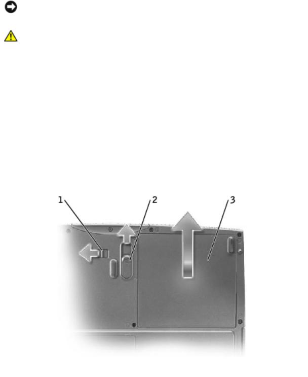
9.Remove the battery:
a.Unlock the battery.
b.Slide and hold the battery latch release all the way up until the left edge of the battery pops up.
c.Remove the battery.
file:///F|/Service%20Manuals/Dell/Latitude/v710-740/begin.htm (2 of 8) [2/28/2004 8:22:07 AM]

Before You Begin: Dell Latitude V710/V740 Service Manual
 1
1  battery lock
2 battery latch release
 3
3  battery
10.To dissipate any static electricity while you work, use a wrist grounding strap or periodically touch an unpainted metal surface.
11.Handle components and cards with care. Do not touch the components or contacts on a card. Hold a card by its edges or by its metal mounting bracket. Hold a component such as a microprocessor by its edges, not by its pins.
Recommended Tools
The procedures in this manual require the following tools:
●#1 magnetized Phillips screwdriver
●¼-inch flat-blade screwdriver
●Nut driver
●Small plastic scribe
●Microprocessor extractor
●Flash BIOS update program floppy disk or CD
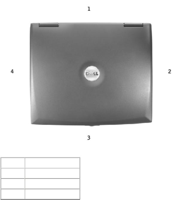
Computer Orientation
file:///F|/Service%20Manuals/Dell/Latitude/v710-740/begin.htm (3 of 8) [2/28/2004 8:22:07 AM]
Before You Begin: Dell Latitude V710/V740 Service Manual
1 |
back |
2 |
right |
3 |
front |
4 |
left |
|
|
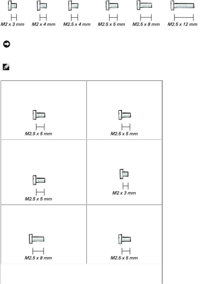
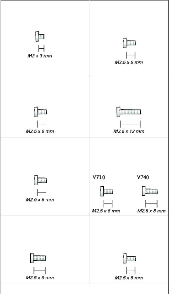
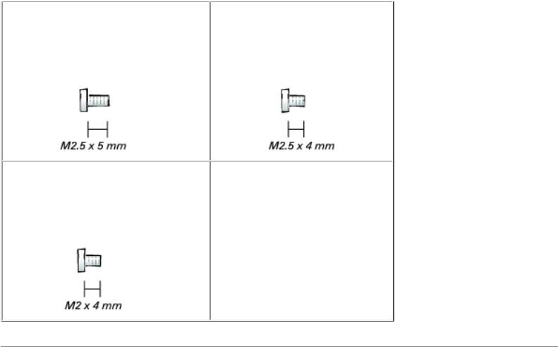
Screw Identification
When you are removing and replacing components, photocopy "Screw Identification"
as a tool to lay out and keep track of the screws. The placemat provides the number of screws and their sizes.
file:///F|/Service%20Manuals/Dell/Latitude/v710-740/begin.htm (4 of 8) [2/28/2004 8:22:07 AM]
Before You Begin: Dell Latitude V710/V740 Service Manual
NOTICE: When reinstalling a screw, you must use a screw of the correct diameter and length. Ensure that the screw is properly aligned with its corresponding hole, and avoid overtightening.
NOTE: All M2.5 x 4 screws are silver, and all other screws are black.
Back-Panel Fan: |
Hard Drive Door: |
(2 each) |
(1 each) |
Memory Module/ |
Modem to System Board: |
Modem Cover: |
|
(1 each) |
(2 each) |
|
Optical Drive: |
Floppy Drive: |
(1 each) |
(2 each) |
file:///F|/Service%20Manuals/Dell/Latitude/v710-740/begin.htm (5 of 8) [2/28/2004 8:22:07 AM]
Before You Begin: Dell Latitude V710/V740 Service Manual
Keyboard Assembly to Hinges: Keyboard to Bottom Case:
(2 each)
(4 each; silver screws)
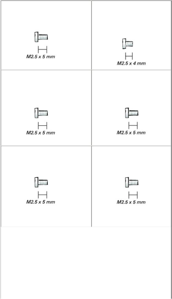
Display Assembly |
Display-Feed Flex Cable |
to Back Panel: |
to System Board: |
(2 each) |
(2 each) |
Hinge Bracket to Bottom Case: Display Bezel:
(4 each) |
(5 each) |
Screw Covers (5 each)
file:///F|/Service%20Manuals/Dell/Latitude/v710-740/begin.htm (6 of 8) [2/28/2004 8:22:07 AM]
Before You Begin: Dell Latitude V710/V740 Service Manual
Display Panel: |
Display-Feed Flex Cable to |
|
Display Assembly: |
(4 each) |
|
|
(1 each) |
Display Latch: |
EMI Shield: |
(2 each) |
(3 each) |
Top of Palm Rest to |
Video Board |
Bottom Case: |
to Bottom Case: |
(2 each) |
(1 each) |
Palm Rest to |
Floppy Drive Cage to |
Bottom Case: |
Bottom Case: |
(12 each) |
(2 each) |
file:///F|/Service%20Manuals/Dell/Latitude/v710-740/begin.htm (7 of 8) [2/28/2004 8:22:07 AM]
Before You Begin: Dell Latitude V710/V740 Service Manual
Hard Drive Cage to |
System Board to |
Bottom Case: |
Bottom Case: |
(2 each) |
(6 each; silver screws) |
Battery Latch Assembly to Bottom Case:
(1 each)
Back to Contents Page
file:///F|/Service%20Manuals/Dell/Latitude/v710-740/begin.htm (8 of 8) [2/28/2004 8:22:07 AM]

System Components: Dell Latitude V710/V740 Service Manual
Back to Contents Page
System Components
Dell™ Latitude™ V710/V740 Service Manual
NOTICE: Only a certified service technician should perform repairs on your computer. Damage due to servicing that is not authorized by Dell is not covered by your warranty.
NOTICE: Unless otherwise noted, each procedure in this document assumes that a part can be replaced by performing the removal procedure in reverse order.
file:///F|/Service%20Manuals/Dell/Latitude/v710-740/system.htm (1 of 3) [2/28/2004 8:22:08 AM]
System Components: Dell Latitude V710/V740 Service Manual
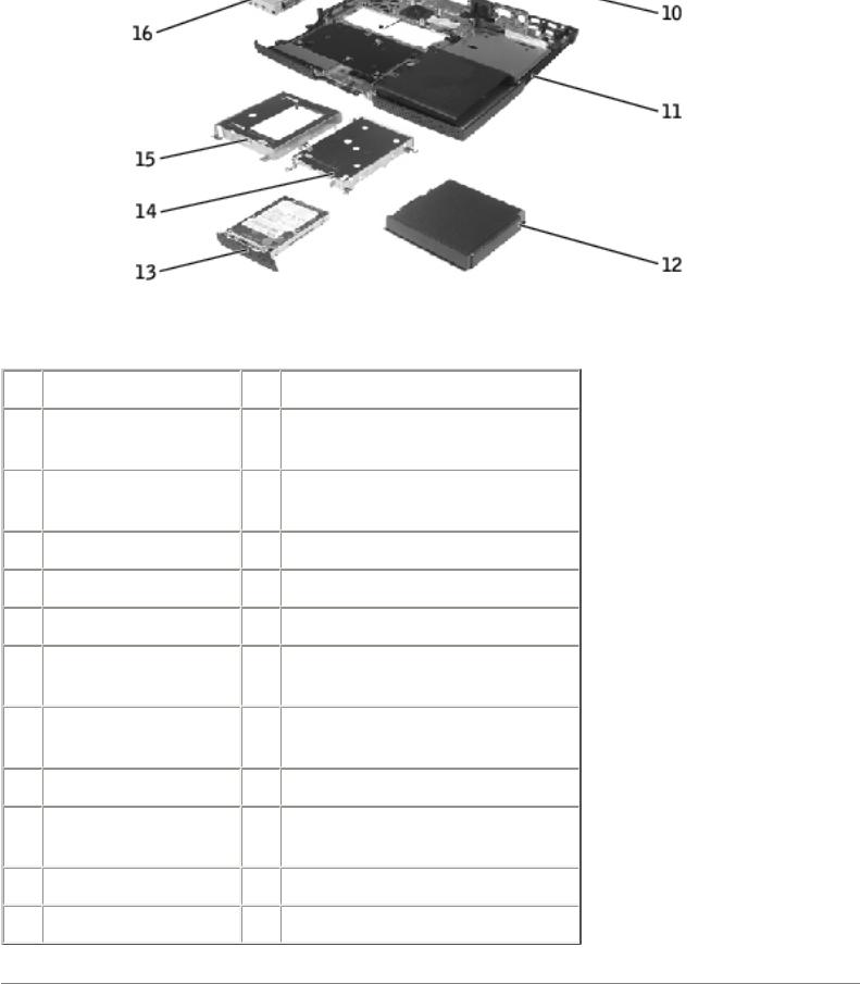
1 |
display assembly |
13 |
hard drive |
2 |
display-feed flex |
14 |
hard drive cage |
|
cable |
|
|
3 |
center control |
15 |
floppy drive cage |
|
cover |
|
|
4 |
keyboard |
16 |
floppy drive |
5 |
video board |
17 |
speaker |
6 |
microprocessor |
18 |
modem |
7 |
system board |
19 |
microprocessor thermal- |
|
|
|
cooling assembly |
8 |
battery connector |
20 |
headphone/microphone |
|
cover |
|
bridge |
9 |
optical drive |
21 |
palm rest |
10 |
back-panel fan |
22 |
memory module/modem |
|
(V740 only) |
|
cover |
11 |
bottom case |
23 |
EMI shield |
12 |
battery |
|
|
Back to Contents Page
file:///F|/Service%20Manuals/Dell/Latitude/v710-740/system.htm (2 of 3) [2/28/2004 8:22:08 AM]
System Components: Dell Latitude V710/V740 Service Manual
file:///F|/Service%20Manuals/Dell/Latitude/v710-740/system.htm (3 of 3) [2/28/2004 8:22:08 AM]

Back-Panel Fan (V740 Only): Dell Latitude V710/V740 Service Manual
Back to Contents Page
Back-Panel Fan (V740 Only)
Dell™ Latitude™ V710/V740 Service Manual
Removing the Back-Panel Fan
NOTICE: To prevent data loss, turn off the computer before removing the backpanel fan. Do not remove the fan while the computer is on or in a power management mode.
NOTICE: Read "Preparing to Work Inside the Computer" before performing the following procedure.
1.Ensure that the work surface is flat and clean to prevent scratching the computer cover.
2.Save and close any open files, exit any open programs, and shut down the computer.
NOTICE: Disconnect the computer and any attached devices from electrical outlets, and remove any installed batteries.
NOTICE: To avoid ESD, ground yourself by using a wrist grounding strap or by touching an unpainted metal surface on the computer.
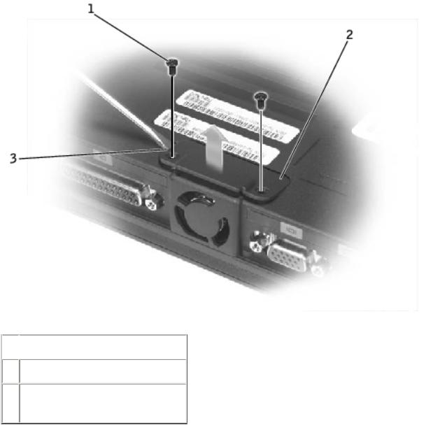
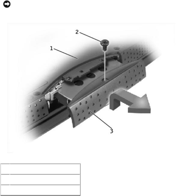
3.Turn the computer over. Use a #1 Phillips screwdriver to remove the two M2.5 x 5-mm screws from the fan cover, and place the screws in a safe location.
file:///F|/Service%20Manuals/Dell/Latitude/v710-740/fan.htm (1 of 4) [2/28/2004 8:22:09 AM]
Back-Panel Fan (V740 Only): Dell Latitude V710/V740 Service Manual
 1
1  M2.5 x 5-mm screws (2)
  2 fan cover
3scalloped left edge of fan cover
4.Use a small flat-blade screwdriver or plastic scribe to lift the scalloped left edge of the fan cover, and pry the cover loose from the bottom case.
5.Lift the fan cover up and away from the bottom case.
6.Disconnect the fan cable connector from the system board.
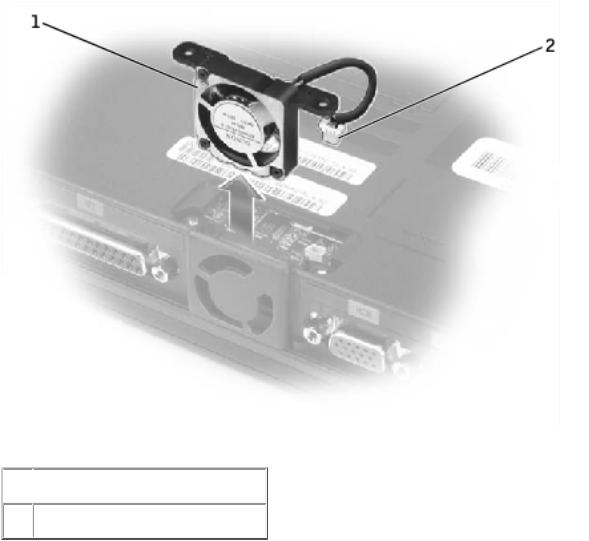
7.Lift the fan out of the bottom case.
file:///F|/Service%20Manuals/Dell/Latitude/v710-740/fan.htm (2 of 4) [2/28/2004 8:22:09 AM]
Back-Panel Fan (V740 Only): Dell Latitude V710/V740 Service Manual
 1
1  fan
fan
2 fan cable connector
Replacing the Back-Panel Fan
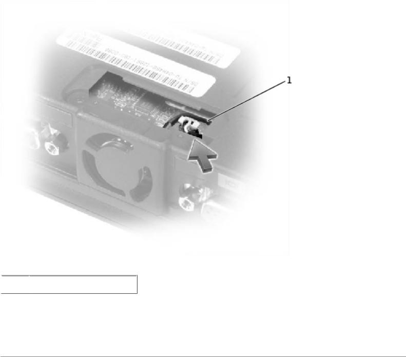
1.Slide the fan into the bottom case.
2.Tuck the fan cable under the bottom case, and connect the cable to the system board.
file:///F|/Service%20Manuals/Dell/Latitude/v710-740/fan.htm (3 of 4) [2/28/2004 8:22:09 AM]
Back-Panel Fan (V740 Only): Dell Latitude V710/V740 Service Manual
 1
1  fan cable
3.Replace the fan cover, and reinstall the two M2.5 x 5-mm screws that secure the cover to the bottom case.
Back to Contents Page
file:///F|/Service%20Manuals/Dell/Latitude/v710-740/fan.htm (4 of 4) [2/28/2004 8:22:09 AM]

Hard Drive: Dell Latitude V710/V740 Service Manual
Back to Contents Page
Hard Drive
Dell™ Latitude™ V710/V740 Service Manual
Removing the Hard Drive
NOTICE: To prevent data loss, turn off the computer before removing the hard drive. Do not remove the hard drive while the computer is on or in a power management mode.
NOTICE: Hard drives are extremely fragile; even a slight bump can damage the drive.
CAUTION: If you remove the hard drive from the computer when the drive is hot, do not touch the metal housing of the hard drive.
NOTICE: Read "Preparing to Work Inside the Computer" before performing the following procedure.
1.Ensure that the work surface is flat and clean to prevent scratching the computer cover.
2.Save and close any open files, exit any open programs, and shut down the computer.
NOTICE: Disconnect the computer and any attached devices from electrical outlets, and remove any installed batteries.
NOTICE: To avoid ESD, ground yourself by using a wrist grounding strap or by touching an unpainted metal surface on the computer.
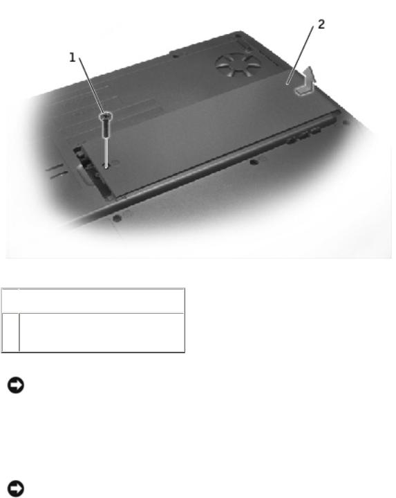
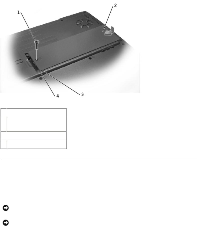
3.Turn the computer over. Use a #1 Phillips screwdriver to remove the M2.5 x 5- mm screw from the hard drive door, and place the screw in a safe location.
file:///F|/Service%20Manuals/Dell/Latitude/v710-740/hdd.htm (1 of 3) [2/28/2004 8:22:09 AM]
Hard Drive: Dell Latitude V710/V740 Service Manual
NOTICE: When the hard drive is not in the computer, store it in protective antistatic packaging.
 1
1  bottom of computer
  2
2  M2.5 x 5-mm screw
  3
3  hard drive door
4.Lift the hard drive door to release it, and slide the hard drive out of the computer.
Replacing the Hard Drive
1. Remove the new drive from its packaging.
Save the original packaging to use when storing or shipping the hard drive.
file:///F|/Service%20Manuals/Dell/Latitude/v710-740/hdd.htm (2 of 3) [2/28/2004 8:22:09 AM]

Hard Drive: Dell Latitude V710/V740 Service Manual
NOTICE: Use firm and even pressure to slide the drive into place. If you force the hard drive into place using excessive force, you may damage the connector.
2.Slide the hard drive into the bay, and press down on the hard drive door until it is fully seated.
3.Replace and tighten the M2.5 x 5-mm screw in the hard drive door.
4.Use the Operating System CD to install the operating system for your computer.
5.Use the Drivers and Utilities CD to install the drivers and utilities for your computer.
Back to Contents Page
file:///F|/Service%20Manuals/Dell/Latitude/v710-740/hdd.htm (3 of 3) [2/28/2004 8:22:09 AM]
Memory Module, Modem, Optical Drive, and Floppy Drive: Dell Latitude V710/V740 Service Manual
Back to Contents Page
Memory Module, Modem, Optical
Drive, and Floppy Drive
Dell™ Latitude™ V710/V740 Service Manual
Memory Module
Modem
Optical Drive
Floppy Drive
Memory Module
Removing the Memory Module/Modem Cover
NOTE: This procedure covers removing and replacing the memory module located under the memory module/modem cover on the bottom of the computer. A second memory module resides on the upper surface of the system board under the EMI shield. To replace the memory module under the EMI shield, perform the procedure for removing the EMI shield. Then replace the
memory module.
NOTICE: Disconnect the computer and any attached devices from electrical outlets, and remove any installed batteries.
NOTICE: To avoid ESD, ground yourself by using a wrist grounding strap or by touching an unpainted metal surface on the computer.
NOTICE: Read "Preparing to Work Inside the Computer" before performing the following procedure.
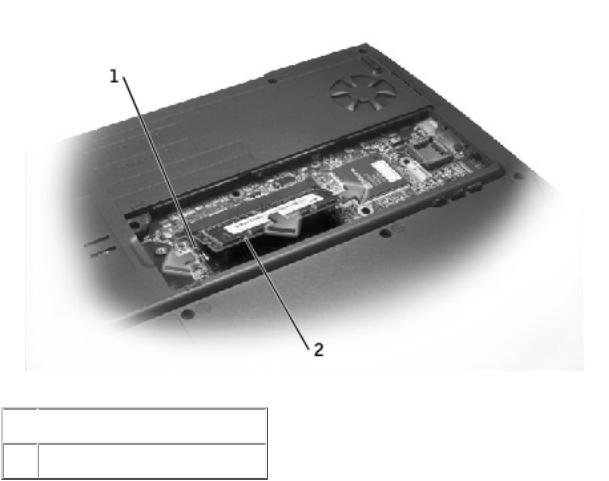
1.Turn the computer over, and remove the memory module/modem cover:
a. Remove the M2.5 x 5-mm screw from the memory module/modem cover.
file:///F|/Service%20Manuals/Dell/Latitude/v710-740/upgrades.htm (1 of 18) [2/28/2004 8:22:11 AM]
Memory Module, Modem, Optical Drive, and Floppy Drive: Dell Latitude V710/V740 Service Manual
b.Slide the cover out approximately 10 mm, and lift it away from the computer.
 1
1  M2.5 x 5-mm screw
2memory module/modem cover
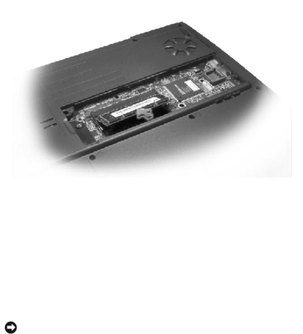
NOTICE: To prevent damage to the memory module connector, do not use tools to spread the inner metal tabs that secure the memory module.
2. If you are replacing a memory module, remove the existing module.
NOTICE: Handle memory modules by their edges, and do not touch the components on a module.
a.Use your fingertips to carefully spread apart the securing clips on each end of the memory module connector.
The module should pop up.
file:///F|/Service%20Manuals/Dell/Latitude/v710-740/upgrades.htm (2 of 18) [2/28/2004 8:22:11 AM]
Memory Module, Modem, Optical Drive, and Floppy Drive: Dell Latitude V710/V740 Service Manual
b. Remove the module from the connector.
 1
1  securing clip
2 memory module
3.Ground yourself and install the new memory module:
a.Align the notch in the module with the slot in the center of the connector.
b.Slide the edge of the module firmly into the connector, and rotate the module down until you hear a click. If you do not hear the click, remove the module and reinstall it.
file:///F|/Service%20Manuals/Dell/Latitude/v710-740/upgrades.htm (3 of 18) [2/28/2004 8:22:11 AM]
Memory Module, Modem, Optical Drive, and Floppy Drive: Dell Latitude V710/V740 Service Manual
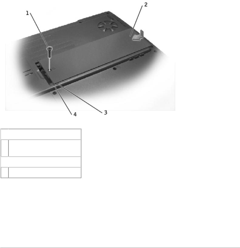
4.Replace the cover and screw:
a.Place the memory module/modem cover over the memory module/modem compartment so that the end of the cover with the screw hole is lined up with the lines and arrows on the bottom of the computer.
b.Press down on the center of the memory module/modem cover, and slide the cover until it is secured.
c.Replace and tighten the M2.5 x 5-mm screw.
NOTICE: If the memory module/modem cover is difficult to close, remove the module and reinstall it. Forcing the cover to close may damage your computer.
file:///F|/Service%20Manuals/Dell/Latitude/v710-740/upgrades.htm (4 of 18) [2/28/2004 8:22:11 AM]
Memory Module, Modem, Optical Drive, and Floppy Drive: Dell Latitude V710/V740 Service Manual
 1
1  M2.5 x 5-mm screw
2memory module/modem cover
 3
3  arrows (2) 4 lines (2)
5.Insert the battery into the battery bay, or connect the AC adapter to your computer and an electrical outlet.
6.Turn on the computer.
As the computer boots, it detects the additional memory and automatically updates the system configuration information.
Modem
file:///F|/Service%20Manuals/Dell/Latitude/v710-740/upgrades.htm (5 of 18) [2/28/2004 8:22:11 AM]
Memory Module, Modem, Optical Drive, and Floppy Drive: Dell Latitude V710/V740 Service Manual
CAUTION: Before performing these procedures, turn off the computer, disconnect it from the electrical outlet, and disconnect the modem from the telephone wall jack.
NOTICE: Disconnect any attached devices from electrical outlets, and remove any installed batteries.
NOTICE: To avoid ESD, ground yourself by using a wrist grounding strap or by touching an unpainted metal surface on the computer.
NOTICE: Read "Preparing to Work Inside the Computer" before performing the following procedure.
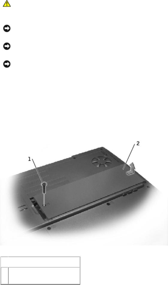
1.Turn the computer over, and remove the memory module/modem cover:
a.Remove the M2.5 x 5-mm screw from the memory module/modem cover.
b.Slide the cover out approximately 10 mm, and lift it away from the computer.
 1
1  M2.5 x 5-mm screw
2memory module/modem cover
file:///F|/Service%20Manuals/Dell/Latitude/v710-740/upgrades.htm (6 of 18) [2/28/2004 8:22:11 AM]
Memory Module, Modem, Optical Drive, and Floppy Drive: Dell Latitude V710/V740 Service Manual
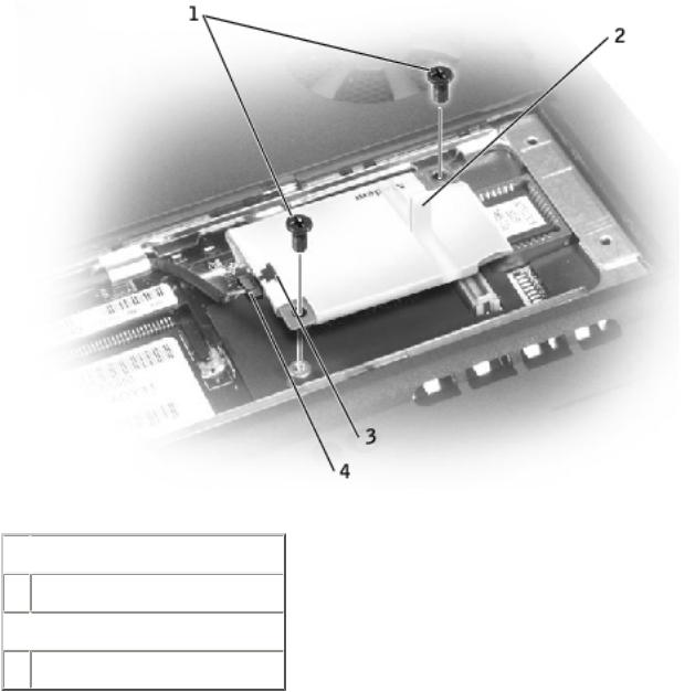
2.If a modem is not already installed, go to step 3. If you are replacing a modem, remove the existing modem:
a.Remove the two M2 x 3-mm screws that secure the modem to the system board, and set them aside.
b.Pull the modem straight up by the pull tab to lift the modem out of its connector, and disconnect the modem cable.
 1
1  M2 x 3-mm screws (2)
2 pull tab
 3
3  modem cable connector
  4 modem cable
3. Connect the modem cable to the new modem.
file:///F|/Service%20Manuals/Dell/Latitude/v710-740/upgrades.htm (7 of 18) [2/28/2004 8:22:11 AM]

Memory Module, Modem, Optical Drive, and Floppy Drive: Dell Latitude V710/V740 Service Manual
NOTICE: The cable connectors are keyed for correct insertion; do not force the connections.
4.Align the modem with the screw holes and press the modem into its connector on the system board.
Install the two M2 x 3-mm screws to secure the modem to the system board.
5.Replace the memory module/modem cover and screw:
a.Place the memory module/modem cover over the memory module/modem compartment so that the end of the cover with the screw hole is lined up with the lines and arrows on the bottom of the computer.
b.Press down on the center of the memory module/modem cover, and slide the cover until it is secured.
c.Replace and tighten the M2.5 x 5-mm screw.
NOTICE: Replace the memory module/modem cover so that it is seated properly around the edges and does not bulge near the center of the cover. Tightening the memory-module/modem cover screw when the cover is improperly seated can damage your computer.
file:///F|/Service%20Manuals/Dell/Latitude/v710-740/upgrades.htm (8 of 18) [2/28/2004 8:22:11 AM]
Memory Module, Modem, Optical Drive, and Floppy Drive: Dell Latitude V710/V740 Service Manual
 1
1  M2.5 x 5-mm screw
2memory module/modem cover
 3
3  arrows (2) 4 lines (2)
Optical Drive
Removing an Installed Optical Drive
NOTICE: To avoid ESD, ground yourself by using a wrist grounding strap or by touching an unpainted metal surface on the computer.
NOTICE: Read "Preparing to Work Inside the Computer" before performing the following procedure.
file:///F|/Service%20Manuals/Dell/Latitude/v710-740/upgrades.htm (9 of 18) [2/28/2004 8:22:11 AM]
 Loading...