


MP2000
RC GROUP
Indice - Index
MP2000 - Controllo a microprocessore per condizionatori
MP2000 - Air conditioners microprocessor control
RC GROUP


MP2000 sistema di controllo a microprocessore per condizionatori
MP2000 air conditioners microprocessor control system
RC GROUP - 149_ItEn.0102
3

MP2000 AIR CONDITIONERS
Sistema di controllo a microprocessore per condizionatori d'aria •
Air conditioners microprocessor control system
GENERALITA' .................................................................................................6 ...................................................................................................
CONFIGURAZIONE HARDWARE MP2000.................................................... 7 ......................................................
Schede BOARD "A" e "B" ......................................................................... 8 ........................................................................
Terminale ................................................................................................. 10 ...................................................................................................
Scheda "ADDR" ....................................................................................... 11 ............................................................................................
Scheda "ADDR+CK" ................................................................................ 12 .....................................................................................
Scheda "T" ............................................................................................... 13 ....................................................................................................
Porta seriale RS485 ................................................................................ 14 .............................................................................
Scheda umidificatore ............................................................................... 15 ........................................................................................
Terminale Remoto "T" .............................................................................. 16 ...............................................................................
POSSIBILI CONFIGURAZIONI DEL SISTEMA MP2000 .............................. 17 ......................................................
Configurazione con BOARD "A" e Terminale a bordo macchina ............. 17 ..............................
Versione con Terminale Remoto "T" ........................................................ 17 ...........................................................
Configurazione con BOARD "A" e "B" e Terminale a bordo macchina .... 19 .................
Versione con Terminale Remoto "T" ....................................................... 19 ...........................................................
CONNESSIONI ELETTRICHE ....................................................................... 21 ..........................................................................
Alimentazione elettrica............................................................................. 21 ........................................................................................
Connessione tra Terminale e scheda BOARD "A" ................................... 21 ......................................................
Connessione tra BOARD "A" e "B" .......................................................... 22 .................................
Connessione tra BOARD "A" e Terminale Remoto "T" ........................... 22 ...................
Connessione seriale RS485 .................................................................... 24 .........................................................................
Connessione sistema di umidificazione ................................................... 26 ...........................................................
Connessione rete LAN ............................................................................ 27 .......................................................................................
Connessione sistema di compensazione set point temperatura ............. 28 .......................
INSERIMENTO DELLA EPROM .................................................................... 29 ..................................................................
FUNZIONI DELLA TASTIERA E PROGRAMMAZIONE ................................ 30 ..........................................
Funzioni della tastiera ..............................................................................30 ..................................................................................
Ritorno alla maschera principale ............................................................. 31 ............................................................................
Partenza random dell'unità ...................................................................... 32 .....................................................................
Funzionamento dell'unità (Ventilatore principale) .................................... 32 ....................................................................
Funzione CHRONO (a richiesta) ............................................................. 32 ..............................................................
Indicazione temperatura uscita aria ......................................................... 34 ..........................................................
Funzione Limit Thermostat ...................................................................... 34 ........................................................................
Inversione senso avviamento compressori ............................................. 35 ..............................................
Presenza allarmi ...................................................................................... 36 .....................................................................................
Visualizzazione ultimi 10 allarmi .............................................................. 36 ....................................................................
Contaore e allarme manutenzione .......................................................... 36 .........................................................
Reset allarmi ............................................................................................37 ..............................................................................................
Comandi manuali ..................................................................................... 37 ...................................................................................
Set point .................................................................................................. 40 ..................................................................................................
Program sets ........................................................................................... 40 ...........................................................................................
Set manufacturer ..................................................................................... 40 .....................................................................................
Memory reset ...........................................................................................41 ..........................................................................................
Calibrazione sonde .................................................................................. 41 ..................................................................................
RETE LOCALE LAN (Local Area Network) ................................................. 42 ........................................................
CONFIGURAZIONE HARDWARE RETE LAN ........................................ 43 .................................
Verifica architettura hardware .................................................................. 43 ....................................................................
Impostazione dei codici di indirizzamento ............................................... 43 ...............................................................................
Codici di indirizzamento ........................................................................... 44 ..........................................................................................
CONFIGURAZIONE SOFTWARE RETE LAN ........................................ 45 ..................................
Verifica automatica della configurazione hardware ................................. 45 ......................................
Configurazione software manuale ........................................................... 46 ................................................................
Elenco maschere ..................................................................................... 48 .................................................................................................
Definizione del numero di unità presenti nella rete .................................. 48 .......................
Condivisione Terminali ............................................................................. 49 ......................................................................................
Funzione CHANGE OVER ...................................................................... 50 ........................................................................
IL SISTEMA DI REGOLAZIONE .................................................................... 53 .................................................
Simbologia utilizzata nei grafici ................................................................ 53 .........................................................................
Gli stadi ON/OFF ..................................................................................... 54 ................................................................................
I segnali proporzionali di temperatura ..................................................... 54 ......................................................
I segnali proporzionali di pressione ......................................................... 55 .............................................................
Le valvole a 3 punti (Floating) ................................................................. 55 ....................................................................................
La funzione LIMIT per la deumidificazione .............................................. 57 ..................................................
Gli allarmi termoigrometrici ...................................................................... 58 ...............................................................
IDENTIFICAZIONE EPROM ........................................................................... 59 .............................................................................
EPROM CZX.... ............................................................................................... 61 ..................................................................................................
Software per condizionatori
Schema INGRESSI/USCITE BOARD "A" ............................................... 62 .................................................
Schema INGRESSI/USCITE BOARD "B" ............................................... 64 .................................................
ELENCO SET .......................................................................................... 66 .................................................................................................
Set point .................................................................................................. 66 ..................................................................................................
Procedura manuale ................................................................................. 66 ...................................................................................
Configurazione unità ................................................................................ 67 ....................................................................................
Parametri generali ................................................................................... 68 ................................................................................
Parametri temporizzazioni ....................................................................... 70 ..................................................................................
Inizializzazione unità ................................................................................ 70 ......................................................................................
Set programmabili.................................................................................... 70 .............................................................................................
ELENCO STATUS ................................................................................... 72 ..........................................................................................
Calibrazione sonde .................................................................................. 74 ....................................................................................
SOMMARIO
Configuration with BOARD "A" and Terminal on unit
Configuration with BOARD "A" and "B" and Terminal on unit
Connection between BOARD "A" and BOARD "B"
Connection between BOARD "A" and "T" Remote Terminal
Temperature set point compensation system connection
LAN NETWORK HARDWARE CONFIGURATION
LAN NETWORK SOFTWARE CONFIGURATION
Definition of the number of units presents in the network
4
SUMMARY
MP2000 HARDWARE CONFIGURATION
BOARD "A" and "B" cards
"ADDR" card
"ADDR+CK" card
RS485 serial port card
Humidifier card
"T" Remote Terminal
MP2000 POSSIBLE CONFIGURATIONS
Version with "T" Remote Terminal
Version with "T" Remote Terminal
ELECTRIC CONNECTIONS
Electric feeding
Terminal and BOARD "A" connection
Serial connection RS485
Humidification system connection
LAN connection
INSTALLATION OF THE EPROM
KEYBOARD FUNCTION AND PROGRAMMING
Keyboard functions
Back to the main menu
Random starting of the unit
Unit switch on (main fan on)
CHRONO function (on request)
Air delivery temperature indication
Limit Thermostat function
Compressors' starting sequence inversion
Alarms presence
Last 10 alarms visualization
Hourmeter and maintenance alarm
Manual procedure
Program sets
Set manufacturer
Memory reset
Sensors calibration
LAN NETWORK (Local Area Network)
Verify hardware architecture
Address code setting
Address code
Automatic check of the hardware configuration
Manual software configuration
Terminal sharing
CHANGE OVER function
PRINCIPLES OF THE CONTROL SYSTEM
Symbols used on graphs
The ON/OFF stages
The temperature proportional signals
The pressure proportional signal
The floating valve
The LIMIT function for dehumidification
The thermohygrometric alarms
EPROM IDENTIFICATION
Software for air conditioners
BOARD "A" INLETS/OUTLETS diagram
BOARD "B" INLETS/OUTLETS diagram
Manual procedure
Unit configuration
General parameters
Timing parameters
Unit initialization
Program set
STATUS LIST
Probes calibration
RC GROUP - 149_ItEn.0102
FOREWORD
Terminal
"T" card
Alarm reset
Set point
Masks list
EPROM CZX
SET LIST
Set point

MP2000 AIR CONDITIONERS
Sistema di controllo a microprocessore per condizionatori d'aria •
Air conditioners microprocessor control system
ELENCO SET MANUALI ......................................................................... 75 .................................................................................
ELENCO MEMO ...................................................................................... 75 .............................................................................................
Logica di raffreddamento con unità ad espansione diretta ...................... 76 ..................................................
Logica di raffreddamento con unità ad espansione diretta+Free-cooling 78 ............................
Funzione Free-cooling (sistema FC) ....................................................... 80 ..........................................................
Logica di funzionamento sistema FC ....................................................... 80 .........................................................................
Logica di raffreddamento con unità ad acqua refrigerata ........................ 82 .........................................................
Logica di riscaldamento con resistenze elettriche ................................... 84 ...........................................................
Logica di riscaldamento con sistema ad acqua calda ............................. 86 ........................................................
Logica di controllo umidità ....................................................................... 88 ..............................................................................
Logica di controllo sistema di deumidificazione ....................................... 89 .....................................................
Logica di controllo della pressione di condensazione ............................. 90 ..........................................................
Logica di compensazione set point temperatura ..................................... 92 ..............................................
EPROM CPX .... ............................................................................................. 93 ..................................................................................................
Software per condizionatori a pompa di calore e Roof Top
Schema INGRESSI/USCITE BOARD "A" ............................................... 94 .................................................
Schema INGRESSI/USCITE BOARD "B" ............................................... 96 .................................................
ELENCO SET .......................................................................................... 98 .................................................................................................
Set point .................................................................................................. 98 ..................................................................................................
Procedura manuale ................................................................................. 98 ...................................................................................
Configurazione unità ................................................................................ 99 ....................................................................................
Parametri generali .................................................................................. 100 ...............................................................................
Parametri temporizzazioni ...................................................................... 102 .................................................................................
Inizializzazione unità ............................................................................... 102 .....................................................................................
Set programmabili ................................................................................... 102 ............................................................................................
ELENCO STATUS .................................................................................. 104 .........................................................................................
Calibrazione sonde ................................................................................. 106 ....................................................................................
ELENCO SET MANUALI ........................................................................ 107 ................................................................................
ELENCO MEMO ..................................................................................... 107 ............................................................................................
Logica di raffreddamento con unità ad espansione diretta ..................... 108 .................................................
Logica di comando apertura serranda Free-Cooling aria esterna .......... 110 .............
Logica di abilitazione e disabilitazione Free-Cooling .............................. 111 ....................................................
Logica di riscaldamento .......................................................................... 112 ...........................................................................................
Logica di controllo umidità ...................................................................... 114 .............................................................................
Logica di controllo della pressione di condensazione ............................ 116 .........................................................
Logica di compensazione set point temperatura .................................... 118 .............................................
Logica di sbrinamento per unità a pompa di calore ................................ 119 ...................................................
ELENCO E DESCRIZIONE ALLARMI .......................................................... 121 ............................................................
Logica di gestione relé di remotizzazione allarmi ................................... 122 ................................
Elenco allarmi ......................................................................................... 123 ...............................................................................................
Descrizione allarmi ................................................................................. 124 ....................................................................................
COMPONENTI DEL SISTEMA MP2000.... ................................................... 135 .................................................
Sonda di temperatura NTC ..................................................................... 136 ........................................................................
Sonda di temperatura ed umidità ........................................................... 137 ..........................................................
Sensore di pressione gas refrigerante .................................................... 138 ............................................................
TA20/4 - Trasformatore amperometrico per corrente umidificatore ........ 139 .....................
TV600 - Trasformatore voltmetrico per tensione di linea ........................ 140 .....................................
TA100 - Trasformatore amperometrico per corrente di linea .................. 141 ................................
TA500 - Trasformatore amperometrico per corrente di linea .................. 142 ................................
RC 275 - Convertitore di tensione .......................................................... 143 ....................................................................
RC 420 - Relè segnalazione presenza acqua + sonda .......................... 144 ...............................................
LV2D - Relè segnalazione presenza acqua + sonda.............................. 145 ...................................................
P11 - Regolatore di velocità per motori monofase .................................. 146 .......................
P12 - Regolatore di velocità per motori monofase ................................. 147 ......................
RIV 1200 - Regolatore di velocità per motori monofase ......................... 148 ..............
DVR - Regolatore di velocità per motori trifase ...................................... 150 ......................
FCS - Regolatore di velocità per motori trifase ....................................... 152 .......................
RC 411A - Convertitore di segnale ad 1 stadio ....................................... 154 ........................................................
RC 470 - Convertitore di segnale a 3 stadi ............................................. 155 ........................................................
RC 460 - Relè di protezione minima corrente (1,5A) .............................. 156 ................................
RC 465 - Relè di protezione minima corrente (10A) ............................... 157 .................................
RC 480a - Dispositivo per unità terminali Flexibox ................................. 158 ...........................................
RC 480b - Dispositivo per unità terminali Flexibox ................................. 159 ...........................................
RCE84.21 - Regolatore ambiente per Flexibox ...................................... 160 ...............................................
RC 285 - Box diodi per segnali 0÷10V ................................................... 162 .................................................
Pressostato differenziale aria ................................................................. 163 ...............................................................
DMS - Servomotore proporzionale per serrande .................................... 164 ................................................
GDB161.1E- Servomotore proporzionale per serrande ......................... 165 .....................................
NM24-SR - Servomotore proporzionale per serrande ............................ 166 .........................................
DAS - Servomotore on/off per serrande ................................................. 167 ...........................................................
SQS-81- Servomotore a 3 punti per valvole ........................................... 168 ....................................................
SQS-65- Servomotore 0÷10V per valvole .............................................. 169 .......................................................
SQX-61- Servomotore 0÷10V per valvole .............................................. 170 .......................................................
FV31 - Regolatore di velocità per motori monofase .............................. 171 ....................
FSF41S - 42S - Regolatore di velocità per motori monofase ................ 172 ......
PS3 - Pressostato on/off per alta/bassa pressione................................. 173 ........................
LDS 004- Pressostato differenziale olio .................................................. 175 ..............................................
EWPC902/T- Termostato elettronico ad 1 stadio .................................... 176 ..........................................
EWPC905/T- Termostato elettronico a 2 stadi ........................................ 178 ........................................
Fan motor speed controller for single phase motor - FSF41S - 42S
Cooling logic with direct expansion unit+Free-cooling
Software for heat pump air conditioners and Roof Top
Control logic for opening the external air Free-Cooling damper
Relay handling logic for the alarms' remote control
Amperometric transformet for humidifier current - TA20/4
Amperometric transformer for line current - TA100
Amperometric transformer for line current - TA500
Fan motor speed controller for single phase motor - P11
Fan motor speed controller for single phase motor - P12
Fan motor speed controller for single phase motor - RIV 1200
Fan motor speed controller for three phase motor - DVR
Fan motor speed controller for three phase motor - FCS
Minimum current protection relay (1,5A) - RC 460
Minimum current protection relay (10A) - RC 465
Fan motor speed controller for single phase motor - FV31
On/off pressure switch for high and low pressure - PS3
Cooling logic with direct expansion unit
Free-cooling function (FC system)
Cooling logic with chilled water unit
Heating logic with electric heaters
Heating logic with hot water system
Dehumidification system control logic
Condensing pressure control logic
Temperature set point compensation logic
BOARD "A" INLETS/OUTLETS diagram
BOARD "B" INLETS/OUTLETS diagram
Cooling logic with direct expansion unit
Free-Cooling enabling/disabling logic
Condensing pressure control logic
Temperature set point compensation logic
Defrosting logic for the heat pump unit
ALARMS LIST AND DESCRIPTION
COMPONENTS OF THE MP2000 SYSTEM
Temperature and humidity sensor
Refrigerant gas pressure sensor
Voltmetric transformetr for line voltage - TV600
Water detection relay + sensor - RC 420
Water detection relay + sensor - LV2D
1-stage signal converter - RC 411A
3-stages signal converter - RC 470
Device for Flexibox terminal unit - RC 480a
Device for Flexibox terminal unit - RC 480b
Room regulator for Flexibox - RCE84.21
Doides box for 0÷10V signals - RC 285
Air differential pressure switch
Proportional actuator for damper - DMS
Proportional actuator for damper - GDB161.1E
Proportional actuator for damper - NM24-SR
On/off actuator for damper - DAS
Floating actuator for valves - SQS-81
0÷10V actuator for valves - SQS-65
0÷10V actuator for valves - SQX-61
Differential oil pressure switch - LDS 004
1-stage electronic thermostat - EWPC902/T
2-stages electronic thermostat - EWPC905/T
MANUAL SET LIST
FC system working logic
Humidity control logic
Manual procedure
Unit configuration
General parameters
Timing parameters
Unit initialization
STATUS LIST
Probe calibration
MANUAL SET LIST
Heating logic
Humidity control logic
Alarm description
NTC temperature sensor
Voltage converter - RC 275
MEMO LIST
EPROM CPX
SET LIST
Set point
Program set
MEMO LIST
Alarms list
RC GROUP - 149_ItEn.0102
5

MP2000 AIR CONDITIONERS
Sistema di controllo a microprocessore per condizionatori d'aria •
Air conditioners microprocessor control system
GENERALITA'
MP2000 è il nuovo controllore programmabile a doppio
microprocessore sviluppato da RC GROUP per applicazioni nel campo del condizionamento dell’aria che consente la gestione di impianti ad alta tecnologia.
Il presente manuale fornisce le necessarie indicazioni per
un uso corretto del sistema.
Se ne raccomanda pertanto un’attenta lettura prima di
impostare o effettuare qualsiasi operazione sul microprocessore.
In particolare sono di seguito precisate le funzioni specifiche del microprocessore installato su apparecchi RC
GROUP, oltre alle caratteristiche principali inerenti il controllo di gestione di apparecchiature per il condizionamento
dell’aria.
Seguono dettagliate spiegazioni delle funzioni che permettono l’impostazione dei regimi di lavoro della macchina, la
lettura delle variabili controllate, la modifica dei valori di
taratura ed il rilevamento delle funzioni in atto.
Le caratteristiche tecniche forniscono i dati relativi all’alimentazione, i tipi e il numero degli ingressi e delle uscite,
i relè di uscita di comando e di segnalazione, ecc.
Da queste informazioni si ricava un quadro dettagliato e
completo sulle capacità di gestione dell’MP2000.
Sono elencate le informazioni di funzionamento, gli allarmi
e le funzioni modificabili, mediante gli opportuni comandi.
Di ciascuna di esse è precisato il campo di taratura, il "set"
di fabbrica, i componenti interessati.
Il manuale Vi metterà in grado di operare nel modo più
idoneo sull’MP2000 del Vostro impianto.
FOREWORD
MP2000 is a new programmable controller based on a
double microprocessor designed by RC GROUP for a wide
range of applications in the air conditioning sectors.
The MP2000 is a powerful and advanced microprocessor
system for the management of high technology systems.
This manual supplies the necessary information for a
correct use of the system.
Therefore we recommend you to read this pamphlet carefully before starting any operations on the microprocessor.
Here are described the specific functions of the microprocessor installed on RC GROUP equipments, as well as the
main characteristics concerning management control for
air conditioners.
Additionally the operational steps will be described.
They show the unit operation setting, the reading of the
controlled variables, the modification of calibration values
and the working status visualization.
The technical characteristics provide the data concerning
microprocessor, type and number of inlets and outlets,
control and warning outlet relays, etc.
From this information you can get a complete and detailed
picture of the MP2000 management capacities.
You can also find a list of the working information, supplied
by the microprocessor, the alarms and functions which can
be modified, through the proper operations.
Calibration range, factory “set”, and concerned components of each function are indicated.
After a careful reading of this manual, you will be able to
work with the MP2000 to use your plant in the best way.
6
RC GROUP - 149_ItEn.0102

MP2000 AIR CONDITIONERS
Sistema di controllo a microprocessore per condizionatori d'aria •
Air conditioners microprocessor control system
Configurazione hardware MP2000
MP2000 hardware configuration
RC GROUP - 149_ItEn.0102
7
MP2000 AIR CONDITIONERS
Sistema di controllo a microprocessore per condizionatori d'aria •
Air conditioners microprocessor control system
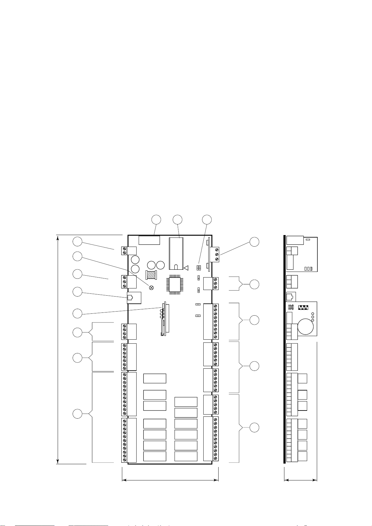
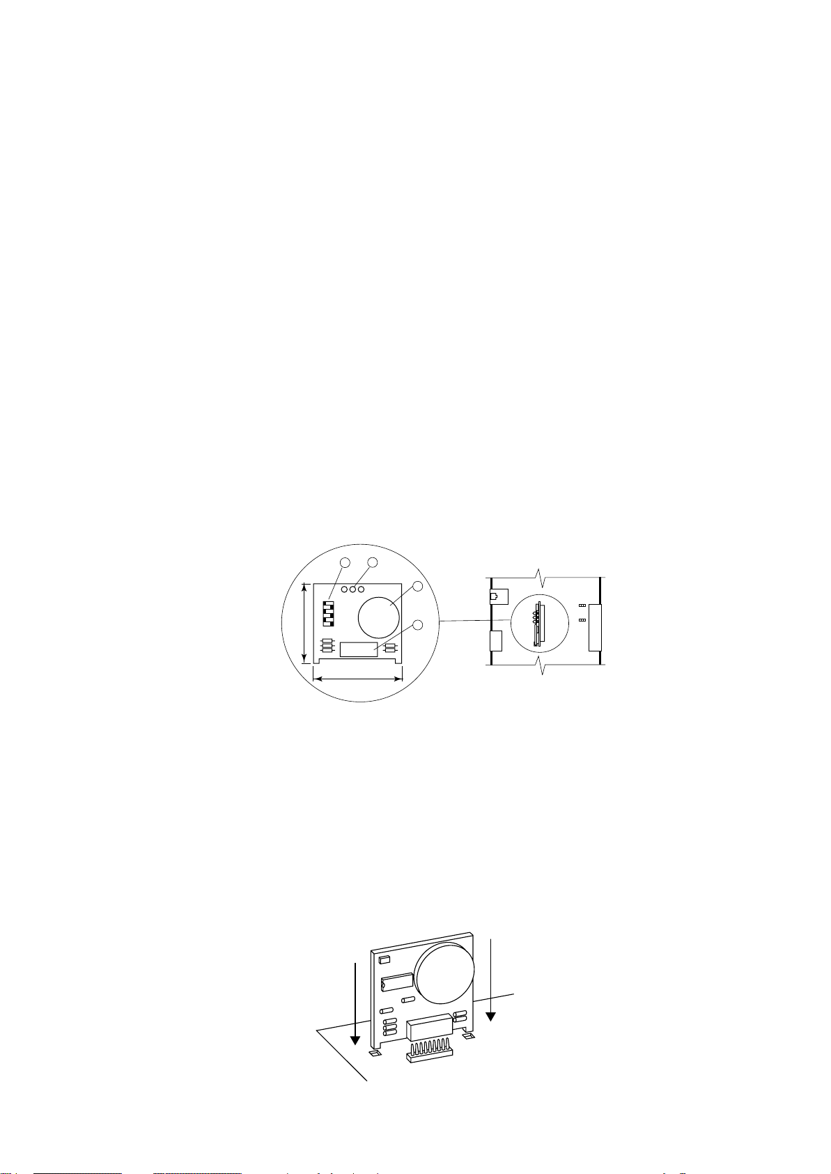
SCHEDE A MICROPROCESSORE - BOARD "A" E "B"
Il sistema di controllo può essere costituito da due schede
elettroniche; la BOARD "A" e la BOARD "B".
La BOARD "A" è la scheda principale ed è dotata di set di
morsetti estraibili necessari alla connessione verso i dispositivi controllati (ad esempio: valvole, compressori, ventilatori, ecc.).
Il programma di gestione è memorizzato su eprom mentre
i parametri impostati sono memorizzati su uno speciale
componente elettronico (Eeprom), che consente il mantenimento dei dati anche in caso di mancanza di alimentazione (senza il bisogno di una batteria di mantenimento).
La scheda BOARD "A" permette anche la connessione
alla rete locale LAN costituita da più schede e più terminali ed il collegamento verso la linea seriale di supervisione/
teleassistenza secondo lo standard RS485 e protocollo di
comunicazione RC-com.
Scheda BOARD "B" è identica alla precedente ed è dota-
ta di set di morsetti estraibili per la remotizzazione dei singoli allarmi e la gestione di alcuni componenti nelle unità
con doppio circuito frigorifero.
16 15
MICROPROCESSOR BOARDS - BOARD "A" AND "B"
The control system can be fitted with two electronic cards;
BOARD "A" and BOARD "B".
BOARD "A" is equipped with a set of plug-in connectors
necessary to connect the board to the controlled devices (e.g. valves, compressors, fans, etc.).
The program is written in the eprom, while the set
parameters are permanently stored (even in case of
power failure) into a special electronic component named
Eeprom.
The BOARD "A" can be linked to a LAN local network,
made by more boards and terminals, or to a supervisory/telemaintenance system via serial line through the
RS485 standard and the new RC-com communication
protocol.
BOARD "B" is equal to the previous one and is equipped
with a set of plug-in connectors for alarms remotization
and for the management of same components in unit with
double cooling circuit.
14
292
J17
J11
J20
J21
J22
J24
J19
FUSE
1
J9 J8
3
2
1
J29
J28
J15
J14
1
1
1
K11
K10
K9
1
K8
K7
K6
K13
K1
K2
K3
K4
K5
K12
RS485
3
2
1
3
2
1
3
1
2
1
321
321
1
1
1
1
1
B8
J1
+24Vcc
B7
B6
AVSS
B5
B4
AVSS
J2
B3
B2
AVSS
B1
IDCM2
ID10
ID9
J3
ID8
ID7
ID6
IDCM1
ID5
ID4
J4
ID3
ID2
ID1
C1
NO1
------
J5
C2
NO2
C3
NO3
-----C4
NO4
------
J6
C5
NO5
-----C12
NO12
13
12
11
10
9
1
G
2
3
G0
GND
RX/TX-
RX/TX+
4
5
VG0
6
7
8
VG1
Y1
Y0
ID11-230Vac
ID11-24Vac
ID11-R
----------ID12-R
ID12-24Vac
ID12-230Vac
NO11
C11
NC11
------
NO10
C10
NC10
-----NO9
C9
NC9
NO8
C8
-----NO7
C7
-----NO6
C6
------
NO13
C13
131
38
Fig. 1
8
RC GROUP - 149_ItEn.0102

MP2000 AIR CONDITIONERS
Sistema di controllo a microprocessore per condizionatori d'aria •
Air conditioners microprocessor control system
1. Connettore per alimentazione 24Vac o 24Vdc (+10% /
-15%) 50/60 Hz - 15VA.
2. LED giallo indicante presenza tensione.
3. Connettore a morsetti estraibili per rete LAN.
4. Connettore telefonico per connessione terminale.
5. Connettore per scheda indirizzamento "ADDR" fornita
di serie.
Scheda indirizzamento+orologio "ADDR+CK" a richiesta.
6. Uscite analogiche 0÷10Vdc optoisolate
• Y: Uscite analogiche 1 e 2, carico max 1kΩ (10mA).
• VG1: Alimentazione esterna per uscite analogiche
(24Vac o 24Vdc).
• VG0: Riferimento per l’alimentazione e per il segna-
le delle uscite analogiche Y0 e Y1.
7. Ingressi digitali optoisolati:
• ID11-230Vac, ID12-230Vac: Ingressi digitali 11 e 12
per segnali a 230Vac.
• ID11-24Vac, ID12-24Vac: Ingressi digitali 11 e 12 per
segnali a 24Vac o 24Vdc ±15%.
• ID11-R, ID12-R: riferimento comune per ingressi di-
gitali ID11 e ID12.
Evitare di portare segnali a 230Vac sul morsetto per
24Vac, pena danneggiamento della scheda stessa.
8. Uscite digitali 2500VA - 250Vac - 10A resistivi:
• NO: Contatto normalmente aperto.
• NC: Contatto normalmente chiuso.
• C: Contatto comune.
9. Uscite digitali 250Vac - 10A resistivi:
• NO: Contatto normalmente aperto.
• C: Contatto comune per il contatto.
10. Ingressi digitali optoisolati 24Vac o 24Vdc (10mA):
• ID: Ingressi digitali 1÷10.
• IDCM1: Riferimento comune ingressi digitali 1÷5.
• IDCM2: Riferimento comune ingressi digitali 6÷10.
11. Ingressi analogici:
• B: Ingresso analogico 1÷6.
• AVSS: riferimento comune degli ingressi analogici B.
• Da B1 a B4 accettano sonde NTC. B5 e B6 sono
selezionabili per sonde con segnale 0÷1Vdc o
4÷20mA tramite ponticelli.
12. Ingressi analogici:
• B: Ingresso analogico 7 e 8.
• +24Vdc: Alimentazione sonde attive e sensori di pres-
sione 4÷20mA (max 80mA).
• Selezionabili per sonde con segnale 0÷1Vdc o
4÷20mA tramite ponticelli.
13. Scheda porta seriale RS485 optoisolata (a richiesta).
14. Ponticelli per impostazioni:
• J8 in posizione 2-3.
• J9 in posizione 2-3.
• J14 selezione dell’ingresso analogico B5
1-2=4÷20mA, 2-3=0÷1Vdc.
• J15 selezione dell’ingresso analogico B6
1-2=4÷20mA, 2-3=0÷1Vdc.
• J28 selezione dell’ingresso analogico B7
1-2=4÷20mA, 2-3=0÷1Vdc.
• J29 selezione dell’ingresso analogico B8
1-2=4÷20mA, 2-3=0÷1Vdc.
15. Eprom contenente programma applicativo.
16. Fusibile 250Vac, 2A ritardato (2TA).
1. 24Vac or 24Vdc power supply connector (+10% / -15%)
50/60 Hz - 15VA.
2. Yellow LED for voltage presence indication.
3. Plug-in connector for LAN network.
4. Telephone-type connector for teminal connection.
5. Connector for address card "ADDR" (standardly supplied).
On request address+clock card "ADDR+CK".
÷
6. Analog outputs 0
• Y: Analog outputs 1 and 2, max load 1k
• VG1: External power supply for analog outputs (24Vac
or 24Vdc).
• VG0: Reference for power supply and analog outputs
signals Y0 and Y1.
7. Opto-insulated digital inputs:
• ID11-230Vac, ID12-230Vac: Digital inputs no. 11
and 12 for 230Vac signals.
• ID11-24Vac, ID12-24Vac: Digital inputs no. 11 and
12 for 24Vac or 24Vdc
• ID11-R, ID12-R: Common references for digital inputs ID11 and ID12.
Never connect the 230Vac signals to the 24Vac terminal; you damage the main board.
8. Digital outputs 2500VA - 250Vac - 10A resistive load:
• NO: Normally open contact.
• NC: Normally closed contact.
• C: Common contact.
9. Digital outputs 250Vac - 10A resistive load:
• NO: Normally open contact.
• C: Common contact.
10. Opto-insulated digital inputs 24Vac or 24Vdc (10mA):
• ID: Digital inputs 1
• IDCM1: Common reference for digital inputs 1
• IDCM2: Common reference for digital inputs 6
11. Analog inputs:
• B: Analogue input 1÷6.
• AVSS: Common reference of the analogue inputs B.
• From B1 to B4 preset to accept NTC sensors. B5 and
B6 selectable to accept either 4
signals through jumper.
12. Analog inputs:
• B: Analogue input 7 and 8.
• +24Vdc: Active probes and pressure probes 4
feeding (max 80 mA).
• Selectable to accept either 4÷20mA or 0÷1Vdc sig-
nals, through jumper.
13. Opto-insulated RS485 serial port (optional).
14. Jumpers for settings:
• J8 in position 2-3.
• J9 in position 2-3.
• J14 - B5 analog input selection
÷
20mA, 2-3=0÷1Vdc.
1-2=4
• J15 - B6 analog input selection
1-2=4÷20mA, 2-3=0÷1Vdc.
• J28 - B7 analog input selection
÷
20mA, 2-3=0÷1Vdc.
1-2=4
• J29 - B8 analog input selection
1-2=4÷20mA, 2-3=0÷1Vdc.
15. Eprom with application program.
16. 250Vac fuse, 2A delayed (2TA).
10Vdc opto-insulated
±
15% signals.
÷
10.
÷
20mA or 0÷1Vdc
Ω
(10mA).
÷
÷
5.
÷
10.
20mA
RC GROUP - 149_ItEn.0102
9
MP2000 AIR CONDITIONERS
Sistema di controllo a microprocessore per condizionatori d'aria •
Air conditioners microprocessor control system
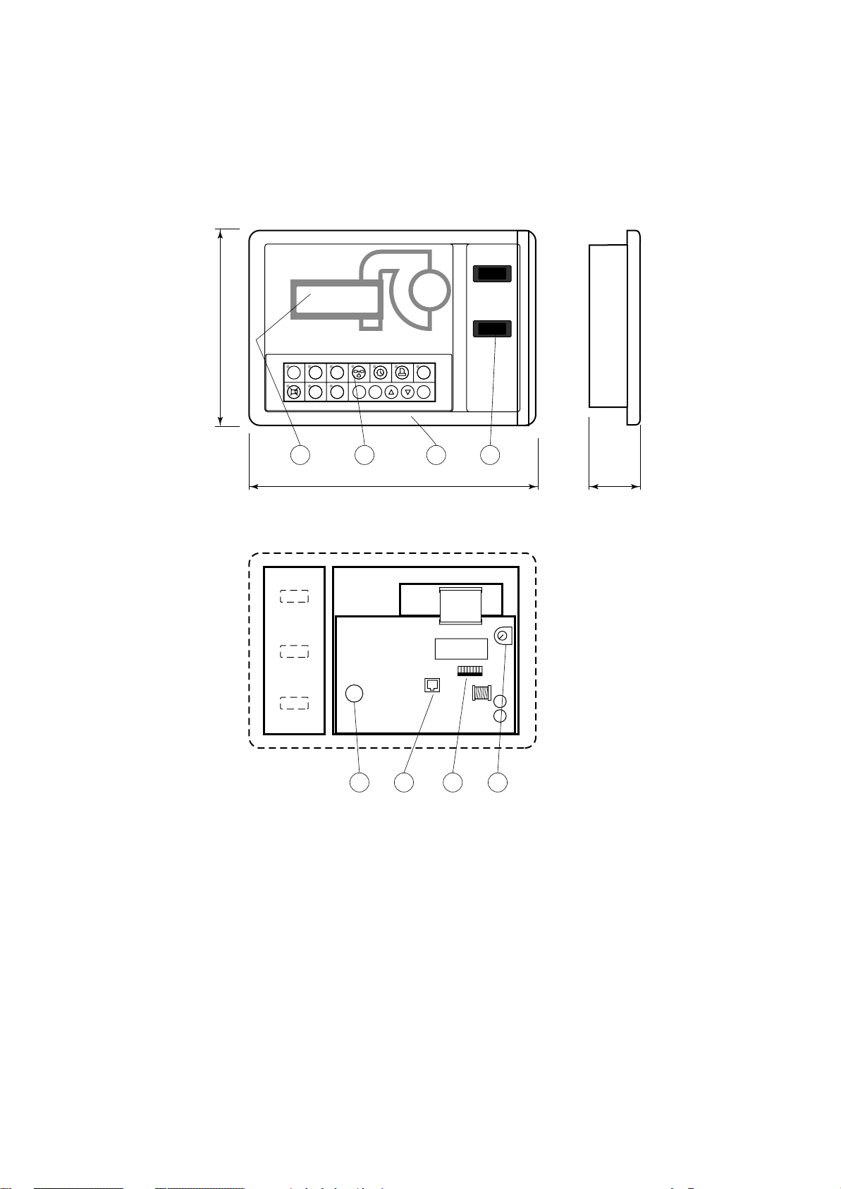
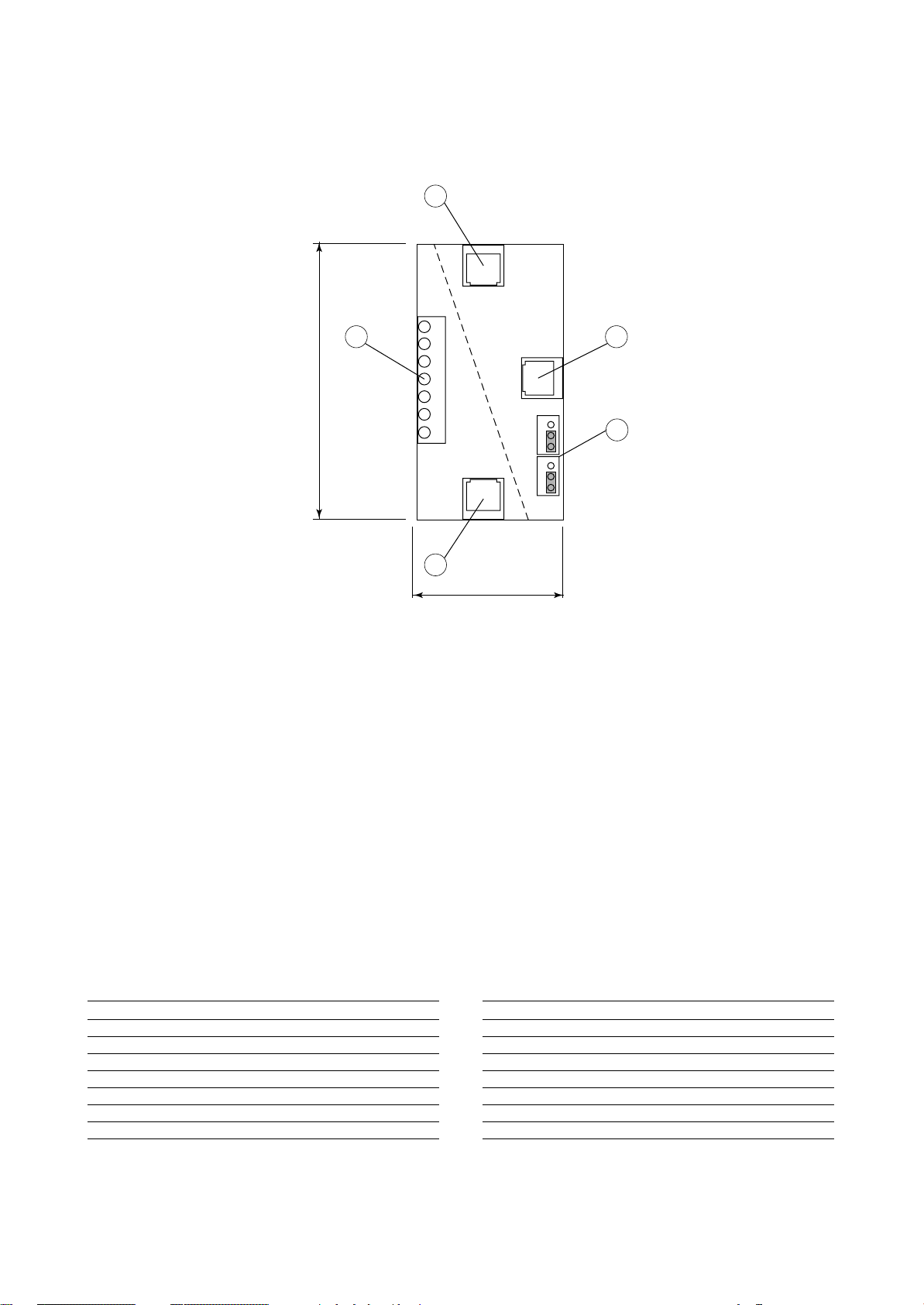
TERMINALE
Il terminale è dotato di display, tastiera e LED per rendere
possibile la programmazione dei parametri di controllo (set
points, differenziali, soglie di allarme) e le operazioni fondamentali da parte dell’utente (on/off, visualizzazione dei
valori controllati).
La connessione del
VISTA FRONTALE TERMINALE
TERMINAL FRONTAL VIEW
terminale alla scheda
BOARD "A" non è necessaria per il funzio-
MP2000
namento a regime
del controllore; può
essere utilizzata per
la programmazione
iniziale dei parametri
fondamentali e consente le seguenti funzioni:
185
HOME SET PRG
1
234
STATUS
ALARM
567
RC GROUP
E
MEMO
I
• la programmazione iniziale della
macchina con accesso protetto da
password per ga-
270
rantirne la sicurezza.
• la possibilità di modificare in qualsia-
VISTA POSTERIORE TERMINALE SENZA COPERCHIO
TERMINAL BACK VIEW WITHOUT COVER
si momento i parametri fondamentali
di funzionamento
protetti da
password.
• la visualizzazione
tramite display degli allarmi rilevati e
la loro segnalazione acustica per
mezzo di un
cicalino.
• la visualizzazione
tramite LED delle
funzioni attive.
• la visualizzazione
5 6 8
di tutte le grandezze misurate.
TERMINAL
The terminal is complete with display, keyboard and LED
indicators allowing you to easily set the main control
parameters (setpoints, differential zone, alarm thresholds)
and carry out the main working operations (on/off, display-
ing controlled variables).
Connection be-
MAN - O - AUT
tween terminal and
BOARD "A" is not
necessary in normal
working conditions.
SUMMER - WINTER
It is necessary only
for initial basic parameters program-
ON/OFF
ENTER
ming with the following functions:
• initial programming
procedure with access protected by a
1
43 2
password.
• possibility of
55
changing the basic
operation parameters any time, without stopping the program.
• indication of any
alarm condition via
acoustic and visual
signals (buzzer and
alarm messages appearing on the dis-
12345678
on
play).
• visualization of the
active functions by
means of LED indicators.
• visualization of the
measured variables.
7
Fig. 2
1. Terminale.
2. Tastiera terminale.
3. Display terminale, 4x20 caratteri.
4. Interruttori ausiliari unità.
5. Suoneria.
6. Connettore telefonico per connessione a scheda
BOARD "A".
7. Dip-switch per impostazione indirizzo rete LAN.
8. Potenziometro per regolazione contrasto display.
10
1. Terminal.
2. Terminal keyboard.
3. Terminal display, 4x20 characters.
4. Auxiliary unit switches.
5. Buzzer.
6. Telephone-type connector for connection to BOARD
"A".
7. Dip-switch for LAN network address setup.
8. Potentiometer for display contrast calibration.
RC GROUP - 149_ItEn.0102
MP2000 AIR CONDITIONERS
Sistema di controllo a microprocessore per condizionatori d'aria •
Air conditioners microprocessor control system
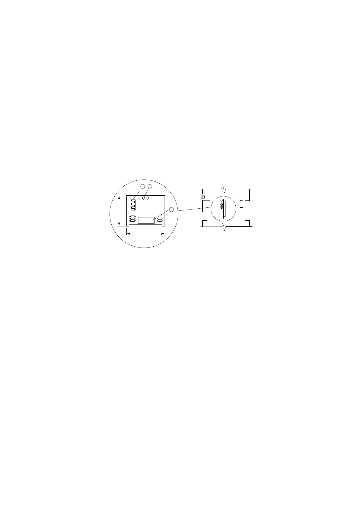
SCHEDA "ADDR"
SCHEDA INDIRIZZAMENTO
La scheda è installata di serie sulla BOARD "A" e sull'eventuale BOARD "B".
La scheda "ADDR" definisce il codice di indirizzamento
necessario al microprocessore per determinare la funzione e l'eventuale posizione nella rete LAN della scheda
BOARD su cui è installata.
Tramite i Dip-switch 1÷6 è possibile impostare il codice di
indirizzamento della scheda.
I LEDs "R" "G" "V" indicano:
"R"incompatibilità hardware (luce rossa intermittente).
incompatibilità software (luce rossa).
"G"trasmissione dati in corso (luce gialla intermittente).
"V" settaggio corretto per la rete LAN (luce verde).
Il LED verde rimane acceso anche se non è prevista la
rete LAN.
1
2
off
1
GV
R
6
39
"ADDR" BOARD
ADDRESS BOARD
This board is standardly installed on BOARD "A" or on the
eventual BOARD "B".
The "ADDR" board allows to fix the address code necessary to the microprocessor to determine the function and
the eventual position in the LAN network of the BOARD on
which it is installed.
÷
Through the Dip-switch 1
6 it is possible to set the board
address code.
The "R" "G" "V" LEDs show:
"R"hardware not compatible (blinking red light).
software not compatible (red light).
"G"data transmission (blinking yellow light).
"V" correct set for the LAN network (green light).
The green LED keeps lighting even if the LAN network
is not foreseen.
J19
3
1
J20
J15
J14
J2
50
1.LEDs "R" "G" "V".
2.Dip-switch per impostazione codice indirizzamento.
3.Connettore.
Fig. 3
1."R" "G" "V" LEDs.
2.Dip-switch for address setting.
3.Connector.
RC GROUP - 149_ItEn.0102
11
MP2000 AIR CONDITIONERS
Sistema di controllo a microprocessore per condizionatori d'aria •
Air conditioners microprocessor control system
SCHEDA "ADDR+CK"
SCHEDA INDIRIZZAMENTO + OROLOGIO
La scheda deve essere installata esclusivamente sulla
BOARD "A" e rimpiazza la scheda "ADDR".
La scheda è equipaggiata con i Dip-switch per l'impostazione dei codici di indirizzamento, con l'orologio a tempo
reale e relativa batteria al litio ricaricabile.
In mancanza di alimentazione, la batteria al litio ricaricabile mantiene attivo l'orologio per oltre un mese (tempo di
carica batteria 12h - 45 mA/h).
La funzione "ADDR" definisce il codice di indirizzamento
necessario al microprocessore per determinare la funzione e l'eventuale posizione nella rete LAN della scheda
BOARD su cui è installata.
Tramite i Dip-switch 1÷6 è possibile impostare il codice di
indirizzamento della scheda.
La funzione "CK" consente la visualizzazione di data ed
ora correnti, data ed ora degli allarmi intervenuti e l'abilitazione della funzione CHRONO (attivazione/spegnimento
unità su fasce orarie).
I LEDs "R" "G" "V" indicano:
"R"incompatibilità hardware (luce rossa intermittente).
incompatibilità software (luce rossa).
"G"trasmissione dati in corso (luce gialla intermittente).
"V" settaggio corretto per la rete LAN (luce verde).
Il LED verde rimane acceso anche se non è prevista la
rete LAN.
"ADDR+CK" BOARD
ADDRESS + CLOCK BOARD
This board must be installed on BOARD "A" only and
replaces the "ADDR" card.
The board is equipped with Dip-switch for the address code
sets and with a real time clock with rechargeable lithium
battery.
In case of power failure, the rechargeable lithium battery
will make the board work for more than one month (rechargeable time 12h - 45 mA/h).
The "ADDR" function allows to fix the address code necessary to the microprocessor to determine the function and
the eventual position in the LAN network of the BOARD on
which it is installed.
÷
Through the Dip-switch 1
6 it is possible to set the board
address code.
The "CK" function allows the current date and time display,
the date and time display of the intervened alarms and the
enabling of the CHRONO function (time-band units control
action).
The "R" "G" "V" LEDs show:
"R"hardware not compatible (blinking red light).
software not compatible (red light).
"G"data transmission (blinking yellow light).
"V" correct set for the LAN network (green light).
The green LED keeps lighting even if the LAN network
is not foreseen.
1
2
off
GV
R
1
6
39
50
Fig. 4
1.LEDs "R" "G" "V".
2.Dip-switch per impostazione codice indirizzamento.
3.Pila al litio per orologio.
4.Connettore.
INSTALLAZIONE SCHEDA
Istruzioni per il corretto montaggio della scheda
"ADDR+CK" sulla scheda BOARD "A":
• Togliere l’alimentazione al sistema prima di inserire/rimuovere la scheda.
• Verificare la posizione esatta prima dell'inserimento della scheda.
• La scheda deve essere infilata negli appositi fori che si trovano ai lati dei contatti.
• Assicurarsi che la scheda sia perfettamente verticale rispetto al connettore per
evitare di danneggiare i contatti.
• Il connettore a pettine deve essere inserito perfettamente fino in fondo.
3
4
J19
1
J20
J15
J14
J2
1.LEDs "R" "G" "V".
2.Dip-switch for LAN network address setting.
3.Lithium battery for real time clock.
4.Connector.
BOARDS INSTALLATION
Instruction for a correct installation of the board "ADDR+CK"
on BOARD "A":
• Switch OFF the system before mounting or removing
the board.
• Identify exactly where the board must be
positioned.
• Insert the board into its dedicated holes.
• When mounting the board make sure it is
perfectly vertical in relation to the main
card in order not to damage the contacts.
• The pin connector must be properly
plugged into the connector.
12
Fig. 5
RC GROUP - 149_ItEn.0102
MP2000 AIR CONDITIONERS
Sistema di controllo a microprocessore per condizionatori d'aria •
Air conditioners microprocessor control system
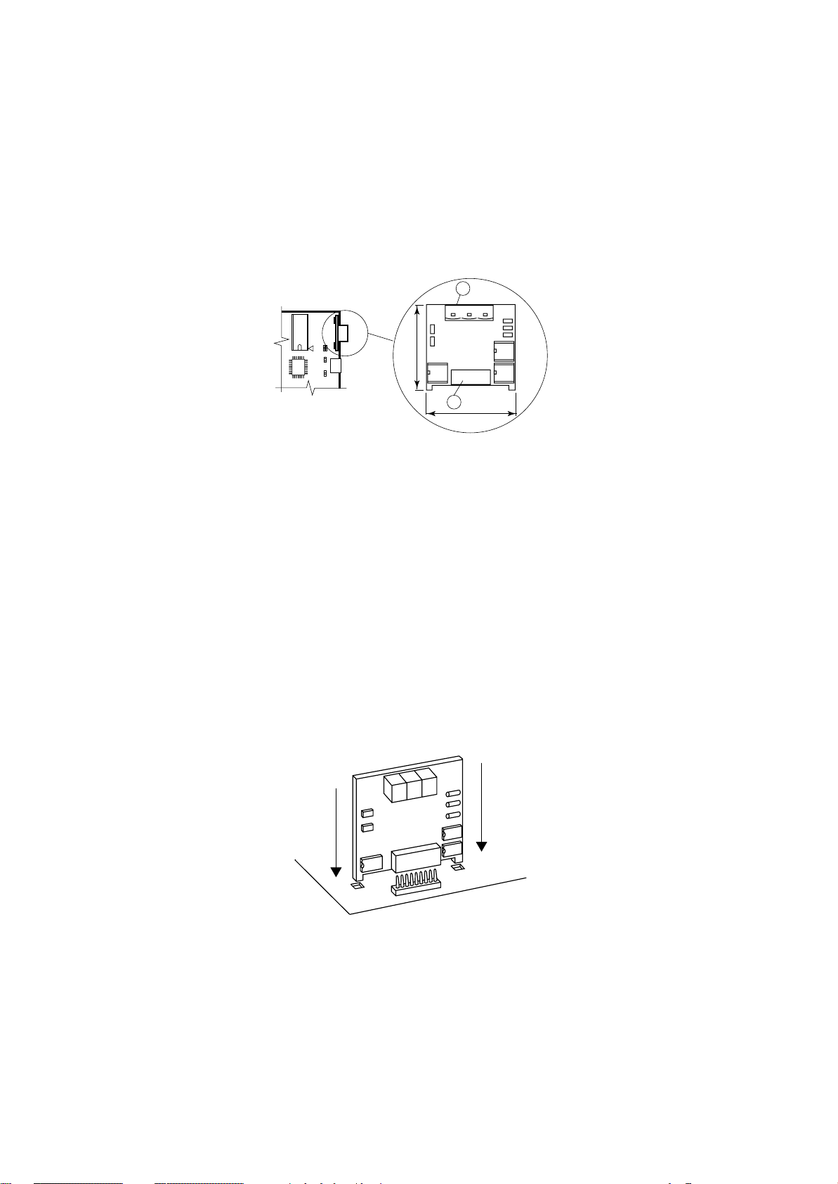
SCHEDA "T"
Questa scheda è essenzialmente un derivatore a T e trova
impiego nel collegamento al terminale remoto "T".
Come indicato in figura la scheda è
equipaggiata con 3 connettori telefonici e con una morsettiera.
Utilizzando la scheda "T" per il
collegamento al Terminale Remoto è necessario predisporre i ponticelli J14 - J15 in posizione 1-2 per
rendere l'alimentazione elettrica
diponibile su tutti i connettori (A-BC-M).
1.Connettore telefonico disponibile per collegamento Board "A" o
Terminale Remoto "T" o Terminale a bordo macchina.
2.Connettore telefonico disponibile per collegamento Board "A" o
Terminale Remoto "T" o Terminale a bordo macchina.
3.Morsettiera per connessione
scheda "T" del Terminale Remoto "T".
4.Connettore telefonico disponibile per collegamento Board "A" o
Terminale Remoto "T" o Terminale a bordo macchina.
5.Ponticelli di settaggio.
32
75
"T" BOARD
This board is essentially a T-derivator used for "T" remote
terminal connection.
1
C
0
1
2
3
M
4
5
6
4
A
35
B
J15
3
2
1
3
2
1
J14
As shown in the picture, the board
is equipped with 3 telephone connectors and terminals.
By using the "T" board for connection to a Remote Terminal, it
is necessary to set the J14-J15
jumpers on 1-2 position. In this
way the electrical feeding is available on all connectors (A-B-CM).
1. Available telephone connector
for Board "A" or "T" Remote Terminal or unit Terminal connec-
5
tion.
2. Available telephone connector
for Board "A" or "T" Remote Terminal or unit Terminal connection.
3. Terminals for "T" board on "T"
Remote Terminal.
4. Available telephone connector
for Board "A" or "T" Remote Terminal or unit Terminal connection.
5. Setting jumpers.
Fig. 6
SETTAGGIO PONTICELLI J14 - J15
Posizione 1 - 2
I tre connettori telefonici A - B - C ed il connettore a vite M
sono posti in parallelo. L'alimentazione è disponibile su
tutti i connettori.
Posizione 2 - 3
L'alimentazione elettrica presente sui connettori B - C è
separata da quella presente sui connettori A - M.
La connessione LAN non viene interrotta tra i vari connettori.
Nel caso i due ponticelli J14 - J15 siano posizionati in
modo differente il derivatore NON funziona.
Conn.M Conn.A-B-C
0 == Calza cavo schermato
1 1 +VRL = 30Vdc
2 2 GND
3 3 Rx- / Tx4 4 Rx+ / Tx+
5 5 GND
6 6 +VRL = 30Vdc
JUMPERS SETTING J14 - J15
Set 1 - 2
The three telephone connectors A - B - C and the screw
connector M are linked in parallel. The power supply is
available on all connectors.
Set 2 - 3
The electrical feeding of B - C connectors is separate from
the one of A - M connectors.
The LAN network is not interrupted among the several
connectors.
In case the two jumpers J14 - J15 are set in different
position, the T-derivator does NOT work.
Conn.M Conn.A-B-C
0 == Braiding of shielded wire
1 1 +VRL = 30Vdc
2 2 GND
3 3 Rx- / Tx4 4 Rx+ / Tx+
5 5 GND
6 6 +VRL = 30Vdc
Quando si usa un cavo schermato il contenitore metallico
del derivatore deve essere collegato a terra.
RC GROUP - 149_ItEn.0102
When a shielded cable is used, the metallic case of the T
derivator must be earthed.
13
MP2000 AIR CONDITIONERS
Sistema di controllo a microprocessore per condizionatori d'aria •
Air conditioners microprocessor control system
PORTA SERIALE RS485
La scheda deve essere installata sulla BOARD "A".
La porta seriale permette l'interfacciamento con una rete
RS485, la scheda garantisce l'optoisolamento del controllo rispetto alla rete seriale RS485.
Il baud-rate massimo è di 19.200 baud, impostabile via
software da tastiera.
Il collegamento all'MP2000 si ottiene posizionando la scheda nel corrispondente connettore a pettine.
RS485
J9 J8
J29
J1
J28
Fig. 7
1.Morsettiera estraibile
2.Connettore.
INSTALLAZIONE SCHEDA
Istruzioni per il corretto montaggio della scheda "RS485"
sulla scheda BOARD "A":
• Togliere l’alimentazione al sistema prima di inseri-
re/rimuovere la scheda.
• Verificare la posizione esatta prima dell'inserimento della scheda.
• La scheda deve essere infilata negli appositi fori che si
trovano ai lati dei contatti.
• Assicurarsi che la scheda sia perfettamente verticale rispetto al connettore per evitare di danneggiare i contatti.
• Il connettore a pettine deve essere inserito perfettamente
fino in fondo.
RS485 SERIAL PORT
This board must be installed on BOARD "A".
The serial port allows interface to a RS485 connection.
This card ensures the controller opto-insulation to the
connection network.
The max baud-rate is 19.200 baud settable via software.
The connection to the controller is obtained when you insert
the card into the relevant plug-in connector.
1
GND RX+
RX-
TX+
TX-
42
2
40
1.Plug-in connector
2.Connector.
BOARD INSTALLATION
Instruction for a correct installation of the board "RS485" on
BOARD "A":
• Switch OFF the system before mounting or removing
the board.
• Identify exactly where the board must be positioned.
• Insert the board into its dedicated holes.
• When mounting the board make sure it is perfectly vertical
in relation to the main card in order not to damage the
contacts.
• The pin connector must be properly plugged into the
connector.
14
Fig. 8
RC GROUP - 149_ItEn.0102
MP2000 AIR CONDITIONERS
Sistema di controllo a microprocessore per condizionatori d'aria •
Air conditioners microprocessor control system
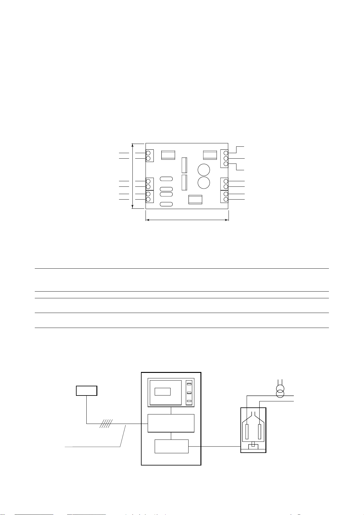
SCHEDA UMIDIFICATORE
Questa interfaccia è essenzialmente un convertitore di
segnale per permettere di controllare i parametri dell'eventuale umidificatore installato sull'unità quali: conducibilità
dell'acqua, livello acqua nel cilindro e assorbimento corrente.
L'alimentazione elettrica della scheda deve essere prelevata esclusivamente dal trasformatore di alimentazione
della scheda BOARD "A".
I sensori di rilevamento non hanno polarità.
La scheda umidificatore è installata all'interno del quadro
elettrico dell'unità in prossimità della BOARD.
67
T1
T2
C1
C2
J3
J2
L1
L2
J1
Sensore corrente (Ax0,2 = valore in Vac)
(vedi trasformatore amperometrico TA20/4)
Current sensor (Ax0,2 = valore in Vac)
(see amperometric transformer 20/4)
Sensore conducibilità
Conductivity sensor
Sensore livello
Level sensor
Fig. 9
HUMIDIFIER BOARD
This interface card is essentially a signal converter to allow
the parameters control of the humidifier eventually installed
on the unit, such as: water conductivity, water level in the
cylinder and current absorption.
It is compulsory to take electric feeding for this card from the
transformer of the BOARD "A".
The sensors do not have polarity.
The humidifier board is installed inside the unit electric box
close to the BOARD.
Uscita analogica 0÷1Vdc - Conducibilità
Analogical output 0÷1Vdc - Conductivity
Riferimento uscite analogiche
Analogical output reference
Uscita analogica 0÷1Vdc - Corrente
Analogical output 0÷1Vdc - Current
Alimentazione elettrica 24Vac
Power supply 24Vac
Uscita digitale alto livello acqua
High water level digital output
84
J6
B8
G0
B7
J5
G
G0
O1
O2
J4
CARATTERISTICHE UMIDIFICATORI
HUMIDIFIER CHARACTERISTICS
Modello Tensione Capacità Potenza Corrente
Model Voltage Capacity Power Current
kg/h kW A
L201MA 230.1.50 2 1,4 6,1
F401TA 230.3.50 3 2,2 5,5
F401TA 400.3.50 5 3,6 5,2
E401TA/1 230.3.50 8 5,8 14,5
E401TA/1 400.3.50 13 9,4 13,6
SCHEMA DI INSTALLAZIONE
Sensore Temperatura/Umidità
Temperature/Humidity sensor
Condizionatore
Air conditioner
TERMINAL
BOARD "A"
INSTALLATION DIAGRAM
Trasformatore amperometrico
Amperometric transformer
Cavo sez. > 0,5mm2
Cable sect. > 0,5 mm2
RC GROUP - 149_ItEn.0102
HUMIDIFIER
BOARD
Umidificatore
Humidifier
Fig. 10
15
MP2000 AIR CONDITIONERS
Sistema di controllo a microprocessore per condizionatori d'aria •
Air conditioners microprocessor control system
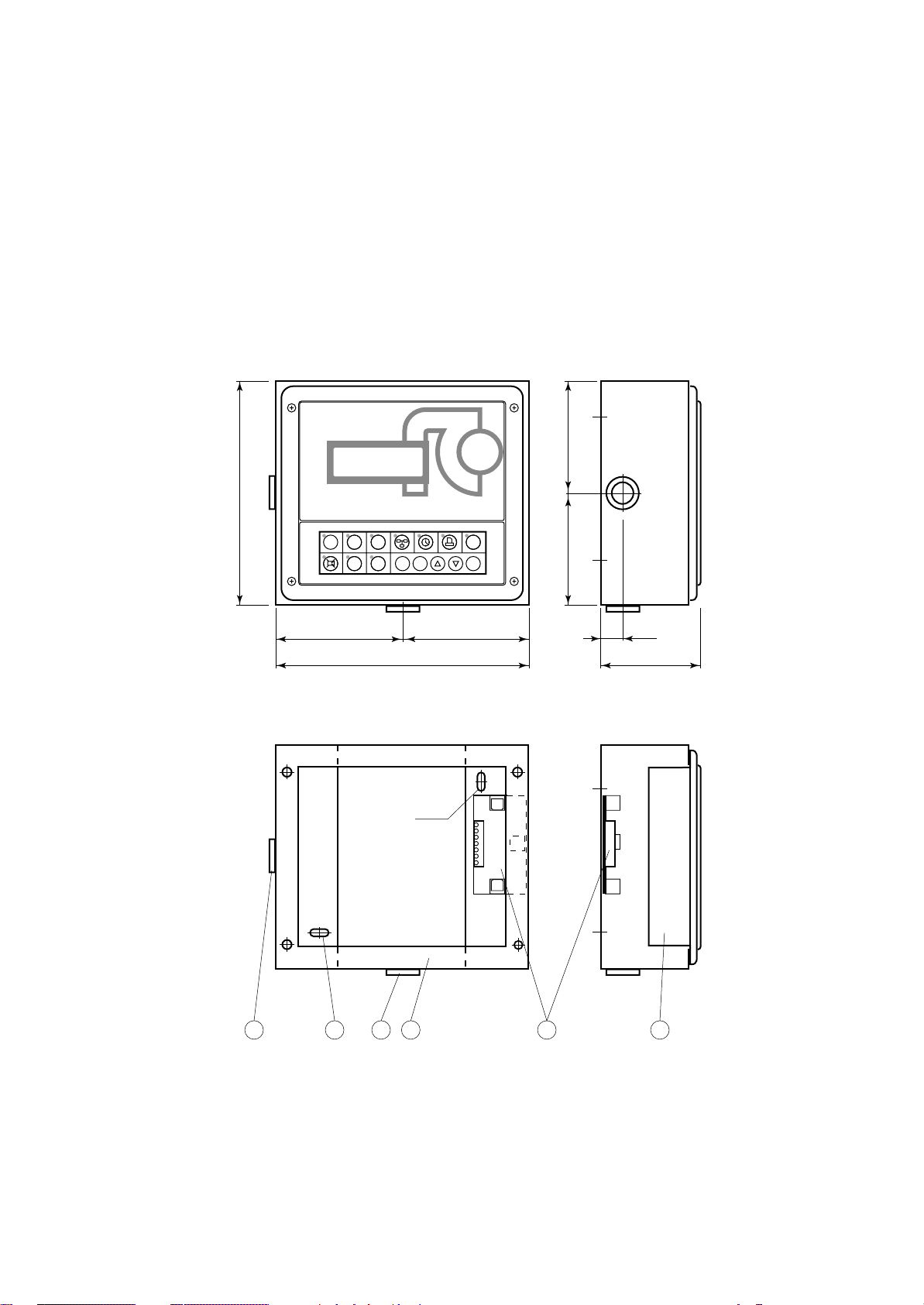
TERMINALE REMOTO "T"
Il terminale remoto "T" viene fornito in kit (kit terminale remoto "T") ed è composto da una scatola di contenimento
in lamiera verniciata contenente il TERMINALE e la scheda "T" per la connessione all'unità.
La scatola di contenimento è predisposta per il fissaggio a
parete e presenta un'apertura nella parte posteriore per il
passaggio del cavo di collegamento tra la scheda "T" e
l'unità.
Il terminale è dotato di display, tastiera e LED per rendere
possibile la programmazione dei parametri di controllo (set
points, differenziali,
soglie di allarme) e le
operazioni fondamentali da parte del-
VISTA CON TERMINALE
VIEW WITH TERMINAL
l’utente (on/off, visualizzazione dei valori
controllati).
MP2000
Come per il terminale a bordo macchina,
il terminale remoto
consente le seguenti
funzioni:
• la programmazione iniziale della
180
HOME SET PRG
1
234
STATUS
ALARM
567
RC GROUP
E
MEMO
I
macchina con accesso protetto da
password per garantirne la sicurezza.
• la possibilità di modificare in qualsia-
==
VISTA SENZA TERMINALE
VIEW WITHOUT TERMINAL
205
si momento i parametri fondamentali
di funzionamento
protetti da
password.
• la visualizzazione
tramite display degli allarmi rilevati e
5x10
la loro segnalazione acustica per
mezzo di un
cicalino.
• la visualizzazione
tramite LED delle
funzioni attive.
• la visualizzazione
di tutte le grandezze misurate.
"T" REMOTE TERMINAL
The "T" remote terminal is supplied in kit ("T" remote
terminal kit) and includes a painted steel sheet box contained the TERMINAL and the "T" board for the connection
to the unit.
The box has a wall mounting predisposition and a back side
opening to allows the connection between the "T" board
and the remote unit.
The terminal is complete with display, keyboard and LED
indicators allowing you to easily set the main control
parameters (setpoints, differential zone, alarm thresholds)
and carry out the
main working operations (on/off, displaying controlled variables).
As described on unit
==
terminal, the remote
terminal allows the
following functions:
• initial programming
procedure with ac-
ON/OFF
ENTER
cess protected by a
password.
• possibility of changing the basic operation parameters any
time, without stop-
20
90
ping the program.
• indication of any
alarm condition via
acoustic and visual
signals (buzzer and
alarm messages appearing on the display).
• visualization of the
active functions by
means of LED indicators.
• visualization of the
measured variables.
1. Terminale.
2. Scheda "T".
3. Fori 5x10 per fissaggio a parete.
4. Scatola di contenimento.
5. Passacavo in gomma 16MV
16
4 2 135 5
Fig. 11
1. Terminal.
2. "T" board.
3. 5x10 holes for wall mounting.
4. Containing box.
5. Rubber fairlead 16MV
RC GROUP - 149_ItEn.0102
MP2000 AIR CONDITIONERS
Sistema di controllo a microprocessore per condizionatori d'aria •
Air conditioners microprocessor control system
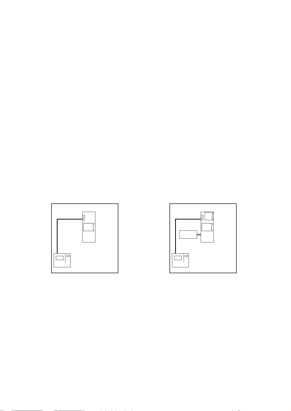
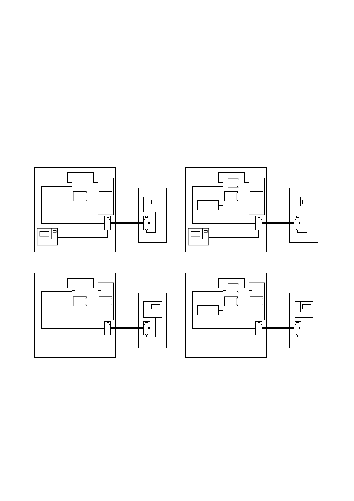
POSSIBILI CONFIGURAZIONI DEL SISTEMA MP2000
CONFIGURAZIONE CON BOARD "A" E TERMINALE A
BORDO MACCHINA
Questo tipo di configurazione è adatta per le seguenti unità:
- Condizionatori alimentati con acqua refrigerata
- Condizionatori equipaggiati con un compressore
- Condizionatori equipaggiati con due compressori su
unico circuito frigorifero.
Il sistema MP2000 comprende la scheda BOARD "A" con
la scheda "ADDR" ed il TERMINALE.
Con questa configurazione il sistema controlla totalmente
l'unità e visualizza sul display tutti gli stati di funzionamento
e gli eventuali allarmi intervenuti.
Per il corretto funzionamento del sistema è necessario
impostare i codici di indirizzamento, indicati tra parentesi
nella figura, sui dip-switch di ogni scheda:
- BOARD "A" codice "2"
- TERMINALE codice "1"
La remotizzazione degli allarmi è possibile solo tramite due
relè di Allarme Generale programmabili con contatto pulito.
A richiesta:
- Porta seriale "RS485"
- Scheda "ADDR+CK"
- Scheda "Umidificatore"
POSSIBLE CONFIGURATIONS OF THE
MP2000 SYSTEM
CONFIGURATION WITH BOARD "A" AND TERMINAL
ON UNIT
This configuration is suitable for the following units:
- Air conditioners with chilled water feeding,
- Air conditioners equipped with one compressor,
- Air conditioners equipped with two compressors working
on a single gas circuit.
The the MP2000 microprocessor control system includes
BOARD "A" with "ADDR" board and TERMINAL.
In this configuration, the system controls the unit showing
on the display all the unit working status and the eventual
intervened alarms.
For a correct system operation it is necessary to set the
address code, between brackets in the picture, on dipswitch of each board.
- BOARD "A" code "2"
- TERMINAL code "1"
The alarms remotization is possible only through two
General Alarm relays with voltage free contact.
On request:
- Serial port "RS485"
- Board "ADDR+CK"
- Board "Humidifier"
STANDARD
ADDR
BOARD
A
(2)
(1)
TERMINAL
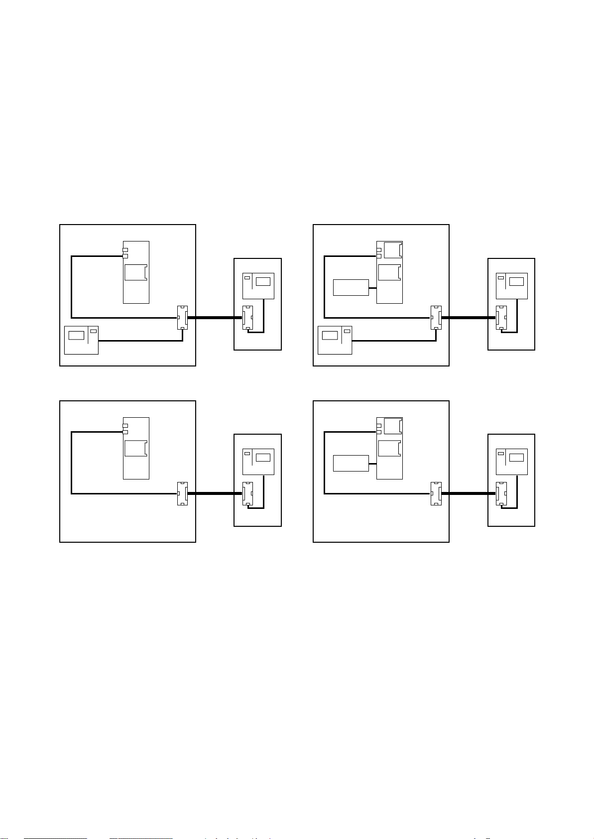
CONFIGURAZIONE CON BOARD "A" E TERMINALE A
BORDO MACCHINA E/O REMOTO "T"
Questa configurazione presenta le stesse caratteristiche
della precedente ma consente la gestione dell'unità anche
dal TERMINALE REMOTO "T".
Per il corretto funzionamento del sistema è necessario
impostare i codici di indirizzamento, indicati tra parentesi
nella figura, sui dip-switch di ogni scheda:
- BOARD "A" codice "2"
- TERMINALE codice "1"
- TERMINALE REMOTO "T" codice "15"
La remotizzazione degli allarmi è possibile solo tramite due
relè di Allarme Generale programmabili con contatto pulito.
La scheda "T" del condizionatore è fornita non installata in
quanto, in caso di rete LAN, deve essere posizionata
sull'unità più vicina al TERMINALE REMOTO "T".
Il TERMINALE REMOTO "T" e la seconda scheda "T" sono
RC GROUP - 149_ItEn.0102
CONDIZIONATORE
AIR CONDITIONER
Fig. 12
OPTIONAL
RS
485
CK
Umidif.
Humidif.
(1)
TERMINAL
ADDR
BOARD
A
(2)
CONDIZIONATORE
AIR CONDITIONER
CONFIGURATION WITH BOARD "A" AND TERMINAL
ON UNIT AND/OR "T" REMOTE
This configuration has the same characteristics of the
previous one, but allows the unit management also from
the "T" REMOTE TERMINAL.
For a correct system operation it is necessary to set the
address code, between brackets in the picture, on dipswitch of each board.
- BOARD "A" code "2"
- TERMINAL code "1"
- "T" REMOTE TERMINAL code "15"
The alarms remotization is possible only through two
General Alarm relays with voltage free contact.
The air conditioner "T" board is supplied not installed
because, in case of LAN network, it has to be positioned on
the unit closest to the "T" REMOTE TERMINAL.
The "T" REMOTE TERMINAL and the second "T" board
17
MP2000 AIR CONDITIONERS
Sistema di controllo a microprocessore per condizionatori d'aria •
Air conditioners microprocessor control system
installati nel box di contenimento per installazione a parete.
Il cavo di collegamento tra le due schede "T" è a cura del
Cliente (max 200m).
A richiesta:
- Porta seriale "RS485"
- Scheda "ADDR+CK"
- Scheda "Umidificatore"
- Detrazione TERMINALE - unità priva di TERMINALE e
controllata dal TERMINALE REMOTO "T".
STANDARD OPTIONAL
Terminale remoto "T"
"T" Remote terminal
TERMINAL
(15)
Scheda T
T board
(1)
TERMINAL
ADDR
BOARD
A
(2)
Scheda T
T board
CONDIZIONATORE
AIR CONDITIONER
are installed in the wall mounting box.
The connection cable between the two "T" boards is by
Customer care (200m max).
On request:
- Serial port "RS485"
- Board "ADDR+CK"
- Board "Humidifier"
- TERMINAL removal - unit without TERMINAL and controlled only by "T" REMOTE TERMINAL.
Terminale remoto "T"
"T" Remote terminal
TERMINAL
(15)
Scheda T
T board
Umidif.
Humidif.
(1)
TERMINAL
RS
485
CK
ADDR
BOARD
A
(2)
Scheda T
T board
CONDIZIONATORE
AIR CONDITIONER
OPTIONAL OPTIONAL
ADDR
BOARD
A
(2)
Scheda T
T board
CONDIZIONATORE
AIR CONDITIONER
Terminale remoto "T"
"T" Remote terminal
TERMINAL
(15)
Scheda T
T board
Umidif.
Humidif.
RS
485
CK
ADDR
BOARD
A
(2)
CONDIZIONATORE
AIR CONDITIONER
Fig. 13
Scheda T
T board
Terminale remoto "T"
"T" Remote terminal
TERMINAL
(15)
Scheda T
T board
18
RC GROUP - 149_ItEn.0102
MP2000 AIR CONDITIONERS
Sistema di controllo a microprocessore per condizionatori d'aria •
Air conditioners microprocessor control system
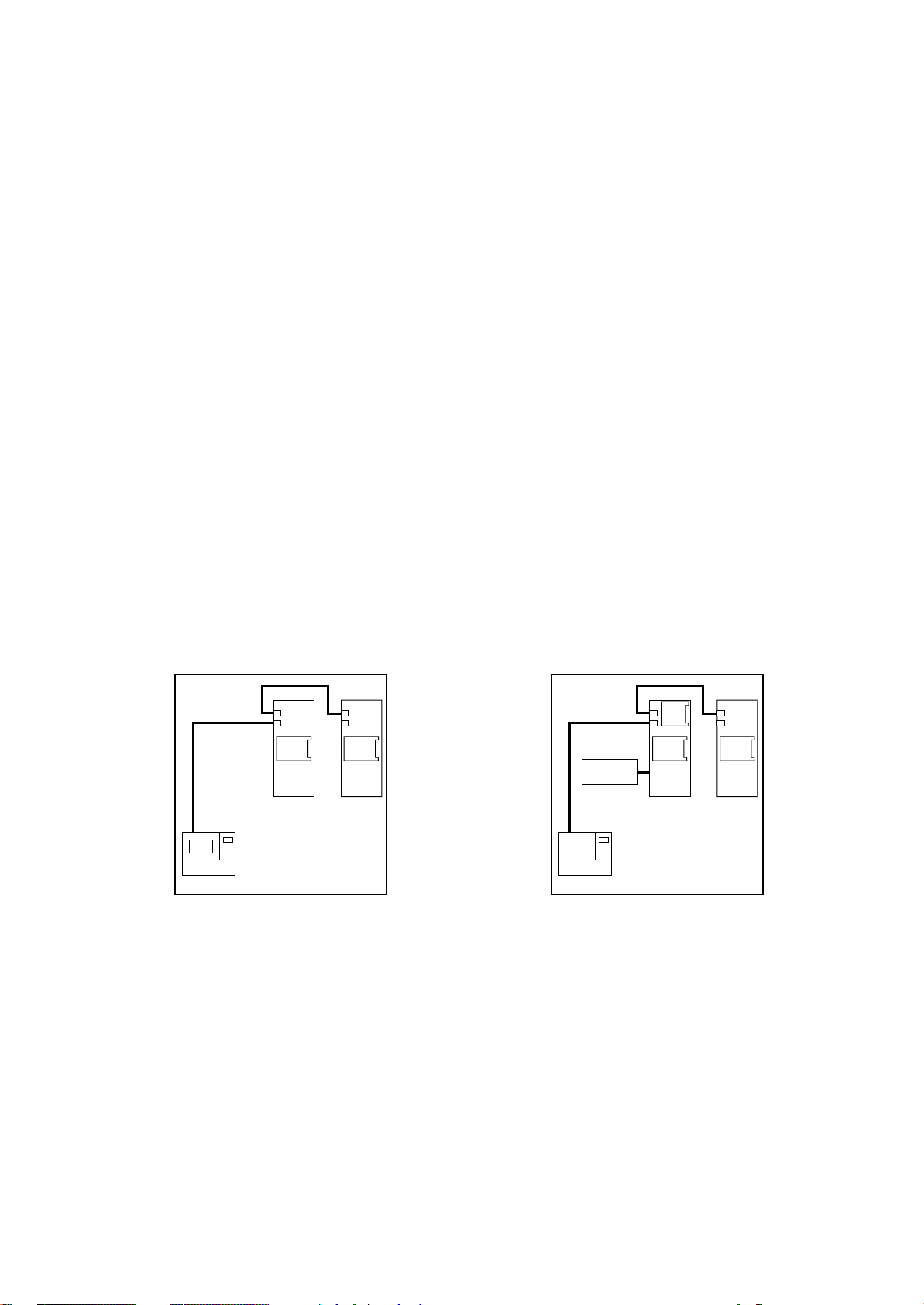
CONFIGURAZIONE CON BOARD "A" E "B" E TERMINALE A BORDO MACCHINA
Questo tipo di configurazione è necessaria per le unità
equipaggiate con due compressori e doppio circuito frigorifero.
A richiesta per tutte le altre tipologie di unità:
- Condizionatori alimentati con acqua refrigerata
- Condizionatori equipaggiati con un compressore
- Condizionatori equipaggiati con due compressori su
unico circuito frigorifero.
Il sistema MP2000 comprende le schede BOARD "A" e "B",
entrambe con la scheda "ADDR" ed il TERMINALE.
Con questa configurazione il sistema controlla totalmente
l'unità e visualizza sul display tutti gli stati di funzionamento
e gli eventuali allarmi intervenuti.
Per il corretto funzionamento del sistema è necessario
impostare i codici di indirizzamento, indicati tra parentesi
nella figura, sui dip-switch di ogni scheda:
- BOARD "A" codice "2"
- BOARD "B" codice "3"
- TERMINALE codice "1"
La remotizzazione degli allarmi è possibile tramite due relè
di Allarme Generale programmabili con contatto pulito
presenti sulla BOARD "A" e tramite specifici relè con
contatto pulito presenti sulla BOARD "B".
A richiesta:
- Porta seriale "RS485" solo per BOARD "A"
- Scheda "ADDR+CK" solo per BOARD "A"
- Scheda "Umidificatore"
CONFIGURATION WITH BOARD "A" AND "B" AND
TERMINAL ON UNIT
This configuration is suitable for units equipped with two
compressors working on two gas circuit.
This configuration is available on request for all other units:
- Air conditioners with chilled water feeding,
- Air conditioners equipped with one compressor,
- Air conditioners equipped with two compressors working
on a single gas circuit.
The MP2000 microprocessor control system includes
BOARD "A" and "B", both with "ADDR" board and TERMINAL.
In this configuration the system controls the unit showing
on the display all the unit working status and the eventual
intervened alarms.
For a correct system operation it is necessary to set the
address code, between brackets in the picture, on dipswitch of each board.
- BOARD "A" code "2"
- BOARD "B" code "2"
- TERMINAL code "1"
The alarms remotization is possible through two General
Alarm relays with voltage free contact on BOARD "A" and
through specific relays with voltage free contacts on BOARD
"B".
On request:
- Serial port "RS485" - only for BOARD "A"
- Board "ADDR+CK" - only for BOARD "A"
- Board "Humidifier"
STANDARD
ADDR
BOARD
B
(3)
(1)
TERMINAL
ADDR
BOARD
A
(2)
CONDIZIONATORE
AIR CONDITIONER
Fig. 14
CONFIGURAZIONE CON BOARD "A" E "B" E TERMINALE A BORDO MACCHINA E/O REMOTO "T"
Questa configurazione presenta le stesse caratteristiche
della precedente ma consente la gestione dell'unità anche
dal TERMINALE REMOTO "T".
Per il corretto funzionamento del sistema è necessario
impostare i codici di indirizzamento, indicati tra parentesi
nella figura, sui dip-switch di ogni scheda:
- BOARD "A" codice "2"
- BOARD "B" codice "3"
- TERMINALE codice "1"
- TERMINALE REMOTO codice "15"
La remotizzazione degli allarmi è possibile tramite due relè
di Allarme Generale programmabili con contatto pulito
presenti sulla BOARD "A" e tramite specifici relè con
contatto pulito presenti sulla BOARD "B".
OPTIONAL
RS
485
Umidif.
Humidif.
(1)
TERMINAL
CK
ADDR
BOARD
A
(2)
CONDIZIONATORE
AIR CONDITIONER
ADDR
BOARD
B
(3)
CONFIGURATION WITH BOARD "A" AND "B" AND
TERMINAL ON UNIT AND/OR "T" REMOTE
This configuration has the same characteristics of the
previous one, but allows the unit management also from
the "T" REMOTE TERMINAL.
For a correct system operation it is necessary to set the
address code, between brackets in the picture, on dipswitch of each board.
- BOARD "A" code "2"
- BOARD "B" code "3"
- TERMINAL code "1"
- REMOTE TERMINAL code "15"
The alarms remotization is possible through two General
Alarm relays with voltage free contact on BOARD "A" and
through specific relays with voltage free contacts on BOARD
"B".
RC GROUP - 149_ItEn.0102
19
MP2000 AIR CONDITIONERS
Sistema di controllo a microprocessore per condizionatori d'aria •
Air conditioners microprocessor control system
La scheda "T" del condizionatore è fornita non installata in
quanto, in caso di rete LAN, deve essere posizionata
sull'unità più vicina al TERMINALE REMOTO "T".
Il TERMINALE remoto e la seconda scheda "T" sono
installati nel box di contenimento per installazione a parete.
Il cavo di collegamento tra le due schede "T" è a cura del
Cliente (max 200m).
A richiesta:
- Porta seriale "RS485" - solo per BOARD "A"
- Scheda "ADDR+CK" - solo per BOARD "A"
- Scheda "Umidificatore"
- Detrazione TERMINALE - unità priva di TERMINALE e
controllata dal TERMINALE REMOTO "T".
STANDARD OPTIONAL
Terminale remoto "T"
"T" Remote terminal
TERMINAL
(15)
Scheda T
T board
(1)
TERMINAL
ADDR
BOARD
A
(2)
ADDR
BOARD
(3)
Scheda T
T board
B
CONDIZIONATORE
AIR CONDITIONER
The air conditioner "T" board is supplied not installed
because, in case of LAN network, it has to be positioned on
the unit closest to the "T" REMOTE TERMINAL.
The remote TERMINAL and the second "T" board are
installed in the wall mounting box.
The connection cable between the two "T" boards is by
Customer care (200m max).
On request:
- Serial port "RS485" - only for BOARD "A"
- Board "ADDR+CK" - only for BOARD "A"
- Board "Humidifier"
- TERMINAL removal - unit without TERMINAL and controlled only by "T" REMOTE TERMINAL.
Terminale remoto "T"
"T" Remote terminal
TERMINAL
(15)
Scheda T
T board
Umidif.
Humidif.
(1)
TERMINAL
RS
485
CK
ADDR
BOARD
A
(2)
ADDR
BOARD
(3)
Scheda T
T board
B
CONDIZIONATORE
AIR CONDITIONER
OPTIONAL OPTIONAL
(3)
Scheda T
T board
ADDR
BOARD
B
ADDR
BOARD
A
(2)
CONDIZIONATORE
AIR CONDITIONER
Terminale remoto "T"
"T" Remote terminal
TERMINAL
(15)
Scheda T
T board
Umidif.
Humidif.
RS
485
CK
ADDR
BOARD
A
(2)
CONDIZIONATORE
AIR CONDITIONER
Fig. 15
ADDR
BOARD
(3)
Scheda T
T board
Terminale remoto "T"
"T" Remote terminal
TERMINAL
B
(15)
Scheda T
T board
20
RC GROUP - 149_ItEn.0102
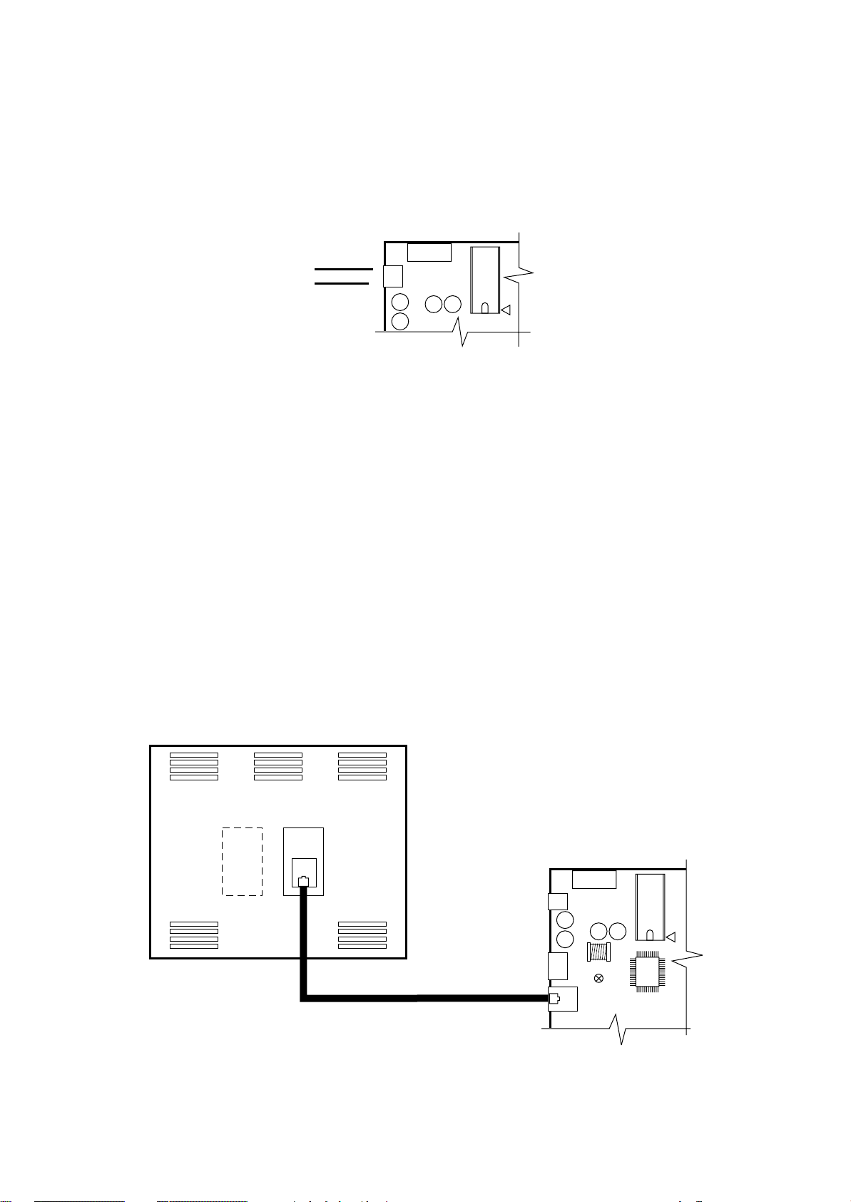
MP2000 AIR CONDITIONERS
Sistema di controllo a microprocessore per condizionatori d'aria •
Air conditioners microprocessor control system
CONNESSIONI ELETTRICHE
ALIMENTAZIONE ELETTRICA
24Vac o 24Vdc (+10% -15%) 50/60 Hz tramite trasformatore.
15VA per alimentazione di ogni scheda BOARD.
1,5VA per alimentazione ingressi digitali ID.
G
24V
CONNESSIONE TRA TERMINALE A BORDO MACCHINA E SCHEDA BOARD "A"
La connessione tra il TERMINALE e la scheda BOARD
"A" viene effettuata tramite cavo telefonico a 6 vie fornito
con l'unità.
Per effettuare il collegamento basta inserire il connettore
telefonico nel morsetto J19 della scheda BOARD "A" e nel
connettore del TERMINALE .
Inserire a fondo il connettore fino ad avvertire lo scatto del
serraggio. Per estrarre il connettore basta premere leggermente sul fermo in plastica sporgente e sfilare il cavo.
La connessione consente l'alimentazione elettrica del TERMINALE (30Vdc) e la trasmissione dati.
La scheda BOARD "A" può funzionare anche senza TERMINALE.
Non scollegare e poi ricollegare il TERMINALE alla
BOARD "A" senza aver atteso circa 5 secondi (qualora
l’operazione venga eseguita a macchina accesa).
J17
G0
Fig. 16
ELECTRIC CONNECTIONS
ELECTRIC FEEDING
24Vac or 24Vdc (+10% -15%) 50/60 Hz through transformer.
15VA for each BOARD feeding.
1,5VA for digital ID inlets feeding.
FUSE
1
CONNECTION BETWEEN TERMINAL ON UNIT AND
BOARD "A"
The connection between TERMINAL and BOARD "A" is
performed by means of a 6-way telephone-type cable
supplied with the unit.
The connection is carried out by plugging the telephone
connector into the connector J19 of the BOARD "A" and
into the connector B of the TERMINAL.
Plug the connector until a click is heard.
To unplug the connector, push gently the prominent plastic
tab and remove the cable.
The connection allows the TERMINAL electrical feeding
(30Vdc) and data transmission.
The BOARD "A" can operate also in absence of terminal
unit.
Anyway, when the system is ON, allow at least 5
seconds between disconnection and following connection of the two units.
VISTA POSTERIORE TERMINALE
TERMINAL BACK VIEW
Fig. 17
MAX 3m
J17
J11
FUSE
1
J19
RC GROUP - 149_ItEn.0102
21
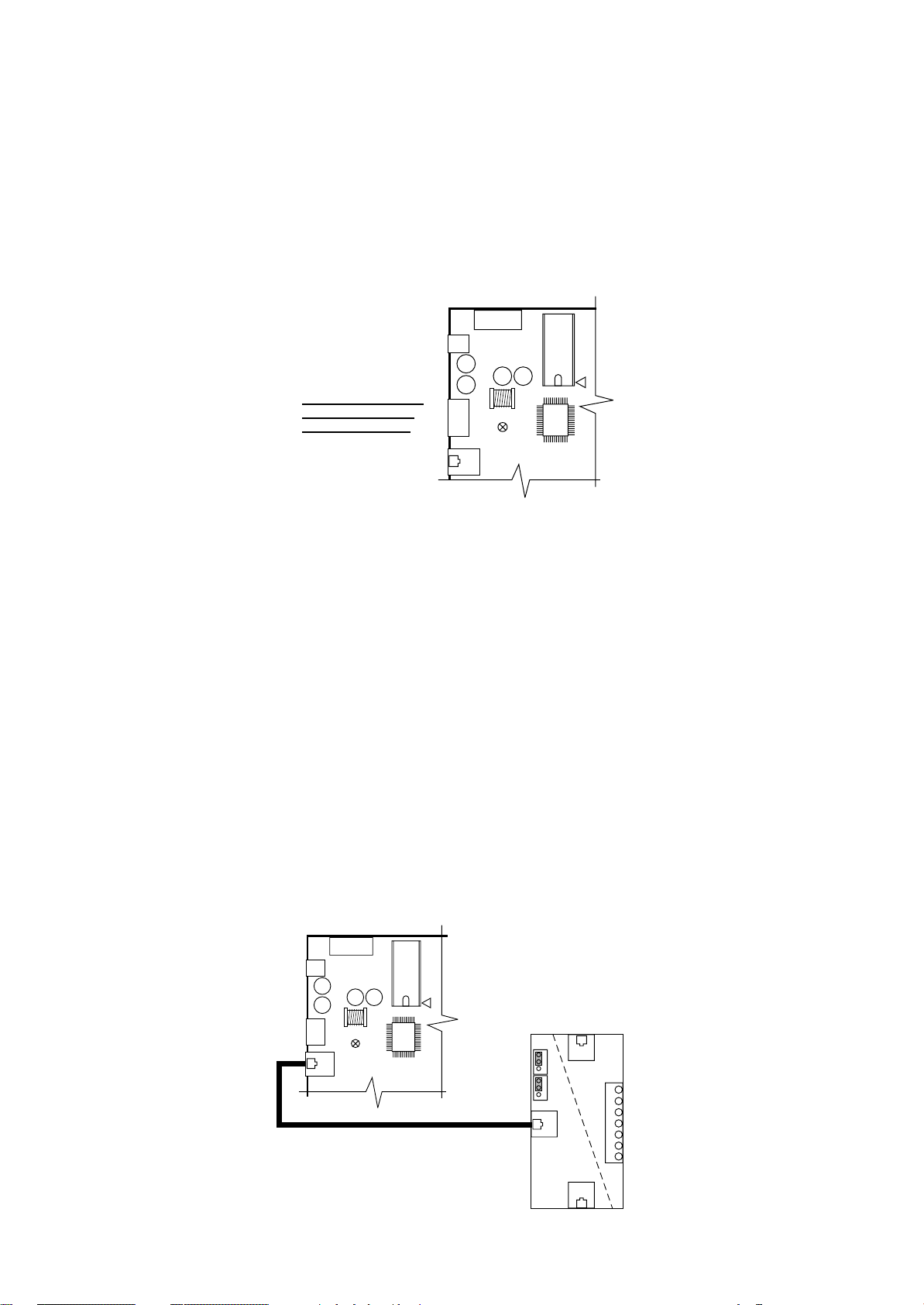
MP2000 AIR CONDITIONERS
Sistema di controllo a microprocessore per condizionatori d'aria •
Air conditioners microprocessor control system
CONNESSIONE TRA BOARD "A" E BOARD "B"
La connessione tra la scheda BOARD "A" e la scheda
BOARD "B" è realizzata in fabbrica con cavo tripolare sui
connettori J11.
La connessione consente lo scambio di informazioni tra le
2 schede.
Per questo tipo di collegamento è utilizzato un cavo elettri-
2
co con sezione di 0,5 mm
.
Non utilizzare il connettore per la connessione seriale.
GND
RX/TX-
RX/TX+
Fig. 18
CONNESSIONE TRA BOARD "A" E TERMINALE REMOTO "T" (max 200m)
La connessione tra la scheda BOARD "A" ed il TERMINALE REMOTO "T" consente l'alimentazione elettrica del
terminale remoto (30Vdc) e lo scambio di informazioni.
La scheda "T" del condizionatore è fornita non installata in
quanto, in caso di collegamento LAN, deve essere posizionata sull'unità più vicina al TERMINALE REMOTO "T".
La connessione interna all'unità tra BOARD "A" e scheda
"T" è da realizzarsi in cantiere con cavo telefonico a 6 vie
(Cavo fornito con "kit Terminale Remoto "T"). E' necessario
predisporre i ponticelli J14 - J15 della scheda "T" in posizione 1-2 per rendere l'alimentazione elettrica diponibile su
tutti i connettori (A-B-C-M).
Inserire a fondo il connettore fino ad avvertire lo scatto del
serraggio. Per estrarre il connettore basta premere leggermente sul fermo in plastica sporgente e sfilare il cavo.
Non scollegare e poi ricollegare il TERMINALE alla
BOARD "A" senza aver atteso circa 5 secondi (qualora
l’operazione venga eseguita a macchina accesa).
CONNECTION BETWEEN BOARD "A" AND BOARD "B"
The connection between BOARD "A" and BOARD "B" is
performed in factory with a three-pole cable on connector
J11.
The connection allows communication exchange between
the 2 cards.
For this connection an electric cable with section of 0,5mm
is utilized.
Don't use the connector for serial connection.
FUSE
1
J17
J11
J19
CONNECTION BETWEEN BOARD "A" AND "T" REMOTE TERMINAL (max 200m)
The connection between BOARD "A" and "T" REMOTE
TERMINAL allows the remote terminal electrical feeding
(30Vdc) and communication exchange.
The air conditioner "T" board is supplied not installed
because, in case of LAN network, it has to be positioned on
the unit closest to the "T" REMOTE TERMINAL.
The connection between BOARD "A" and "T" board has to
be effectuated with a 6-way telephone-type cable (the
cable is supplied with "T Remote Terminal kit"). It is
necessary to set the J14-J15 jumpers of the "T" card on 12 position. In this way the electrical feeding is available on
all connectors (A-B-C-M).
Plug the connector throughly until a click is heard.
To unplug the connector, push gently the prominent plastic
tab and remove the cable.
Anyway, when the system is ON, allow at least 5
seconds between disconnection and following connection of the two units.
2
22
GND
RX/TX-
RX/TX+
FUSE
1
G
J17
G0
J11
J19
J14
A
J15
BM
6
5
4
3
2
1
0
C
Fig. 19
RC GROUP - 149_ItEn.0102

MP2000 AIR CONDITIONERS
Sistema di controllo a microprocessore per condizionatori d'aria •
Air conditioners microprocessor control system
La connessione tra scheda "T" a bordo macchina e scheda
"T" del TERMINALE REMOTO "T" è a cura del Cliente.
Per questo tipo di collegamento utilizzare un cavo scher-
2
mato a 3 coppie intrecciate con sezione di 0,5 mm
(tipo
AWG20) per una lunghezza massima complessiva di 200m.
Lo schermo del cavo deve essere collegato sul morsetto
"0" della scheda "T".
J14
1
2
3
1
2
3
J15
BM
A
6
5
4
3
2
1
0
+VRL = 30Vdc
GND
Rx+ / Tx+
Rx– / Tx–
GND
+VRL = 30Vdc
C
The connection between the unit "T" card and the "T" card
of the "T" REMOTE TERMINAL is by Customer care.
For this connection please use a three twisted-pair shielded
2
cable with section of 0,5mm
(type AWG20) with max
length of 200m.
The shield must be connected to the "0" terminal of the "T"
card.
COPPIA 1 -
COPPIA 2 -
COPPIA 3 -
CALZA -
SHIELD
PAIR 1
PAIR 2
PAIR 3
Fig. 20
La connessione tra la scheda "T" del TERMINALE REMOTO "T" ed il relativo TERMINALE è realizzata con cavo
telefonico a 6 vie (Cavo fornito con kit "Terminale Remoto"). E' necessario predisporre i ponticelli J14 - J15 della
scheda "T" in posizione 1-2 per rendere l'alimentazione
elettrica diponibile su tutti i connettori (A-B-C-M).
Inserire a fondo il connettore fino ad avvertire lo scatto del
serraggio.
Per estrarre il connettore basta premere leggermente sul
fermo in plastica sporgente e sfilare il cavo.
VISTA POSTERIORE TERMINALE REMOTO "T"
"T" REMOTE TERMINAL BACK VIEW
J14
J15
The connection between "T" card and "T" REMOTE TERMINAL is performed by means of a 6-way telephone-type
cable (the cable is supplied with "Remote Terminal" kit).
It is necessary to set the J14-J15 jumpers of the "T" card on
1-2 position. In this way the electrical feeding is available on
all connectors (A-B-C-M).
Plug the connector throughly until a click is heard.
To unplug the connector, push gently the prominent plastic
tab and remove the cable.
A
6
5
4
BM
3
2
1
0
+VRL = 30Vdc
GND
Rx+ / Tx+
Rx– / Tx–
GND
+VRL = 30Vdc
COPPIA 1
PAIR 1
COPPIA 2
PAIR 2
COPPIA 3
PAIR 3
RC GROUP - 149_ItEn.0102
C
Fig. 21
23
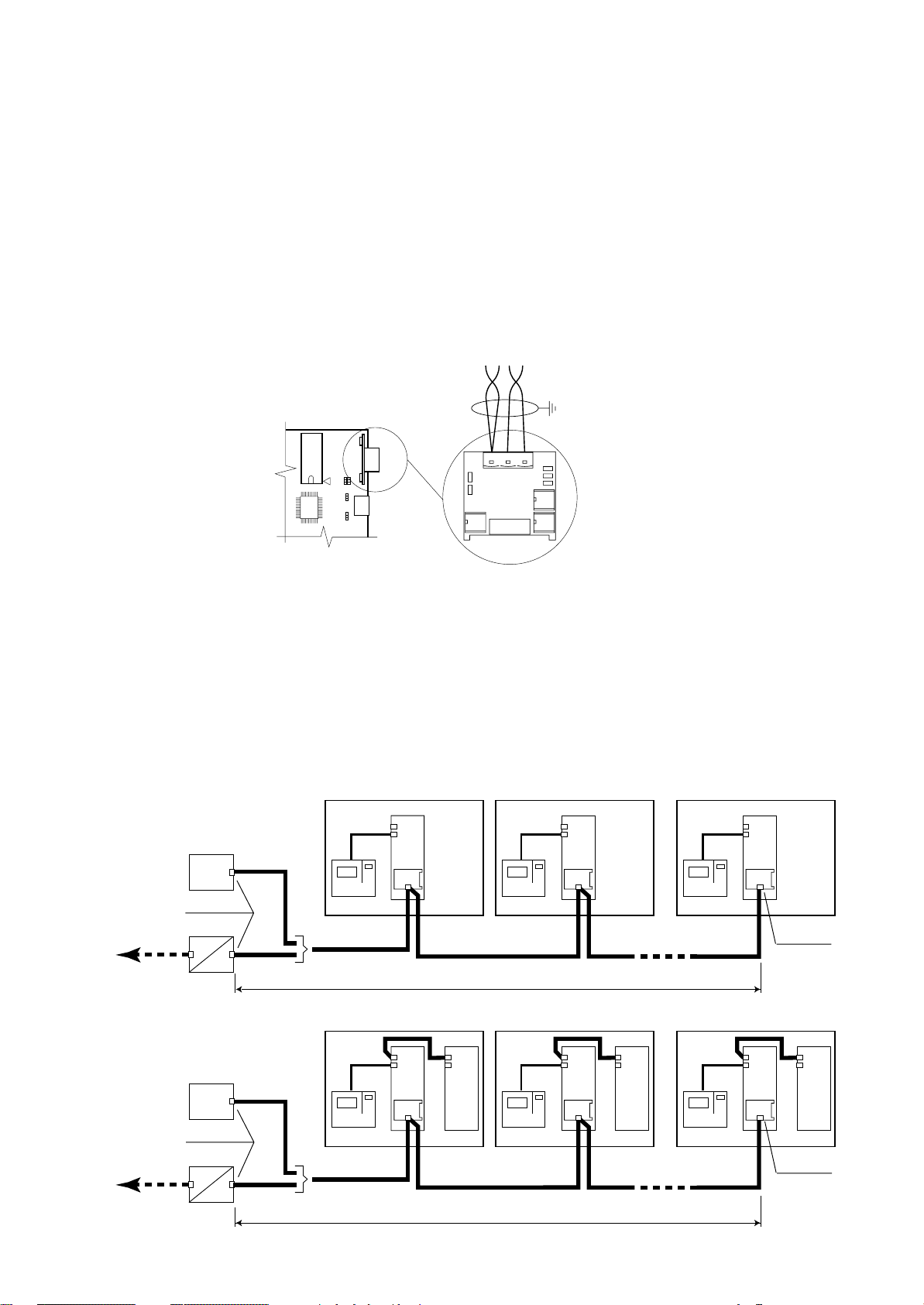
MP2000 AIR CONDITIONERS
Sistema di controllo a microprocessore per condizionatori d'aria •
Air conditioners microprocessor control system
CONNESSIONE SERIALE RS485
La connessione è a cura del Cliente.
La connessione RS485 deve essere realizzata secondo
le normative ISO/IEC 8482 - 1993 (Information Technology
- Telecommunication and information exchange between
systems - Twisted-pair multipoint interconnections).
La scheda è installata sulla BOARD "A" e per questo tipo
di collegamento utilizzare un cavo schermato a 2 coppie
intrecciate con sezione di 0,22 mm
2
(tipo AWG24). Una
sola estremità dello schermo del cavo deve essere collegata a terra.
RC GROUP declina ogni responsabilità per una non
corretta esecuzione del collegamento.
COPPIA 1
RS485
J9 J8
J29
J1
J28
Fig. 22
SERIAL CONNECTION RS485
Connection is by Customer care.
The RS485 connection must be performed according to
ISO/IEC 8482 - 1993 (Information Technology - Telecommunication and information exchange between systems Twisted-pair multipoint interconnections).
This board is installed on BOARD "A" and for this connection please use a two twisted-pair shielded cable with
section of 0,22mm
2
(type AWG24).
Only one shielded-end must be connected to ground.
RC GROUP is not responsible for any wrong connection.
GND RX+
TX+
COPPIA 2
PAIR 2
RXTX-
PAIR 1
Collegamento seriale con protocollo di comunicazione "RC-com" per massimo 32 unità collegate in multipunto.
- Collegamento diretto:
La linea seriale RS485 è collegata direttamente ad un
sistema di supervisione locale.
- Collegamento con GATEWAY-MODEM:
Il collegamento prevede la connessione via modem ad
un supervisore remoto.
Estensione complessiva massima della linea seriale 1.200m.
SISTEMA SUPERVISIONE
SUPERVISION SYSTEM
RS232
GATEWAY - MODEM
RC-com protocol
Protocollo RC-com
SISTEMA SUPERVISIONE
SUPERVISION SYSTEM
Inizio linea
Start line
RS485
RS485
RS485
UNITA' 1 •
TERMINAL
Protocollo RC-com
RC-com protocol
UNITA' 1 •
UNIT 1
BOARD
A
UNIT 1
BOARD
A
Serial connection with "RC-com" communication protocol for max 32 units in multipoint connection.
- Direct connection:
The RS485 serial line is directly connected to a local
supervision system.
- Connection with GATEWAY-MODEM:
Connection via modem to a remote supervision system.
Max length of the serial line 1.200m.
UNITA' 32 •
TERMINAL
UNITA' 32 •
RS485
MAX 1.200m
BOARD
B
UNITA' 2 •
TERMINAL
UNITA' 2 •
UNIT 2
BOARD
A
RS485
MAX 32 UNITA'
MAX 32 UNITS
UNIT 2
BOARDABOARD
B
UNIT 32
BOARD
A
UNIT 32
BOARD
A
RS485
Fine linea
End line
BOARD
B
RC-com protocol
Protocollo RC-com
24
Inizio linea
Start line
RS232
GATEWAY - MODEM
RS485
TERMINAL
Protocollo RC-com
RC-com protocol
Fig. 23
RS485
MAX 1.200m
TERMINAL
RS485
TERMINAL
MAX 32 UNITA'
MAX 32 UNITS
RC GROUP - 149_ItEn.0102
RS485
Fine linea
End line
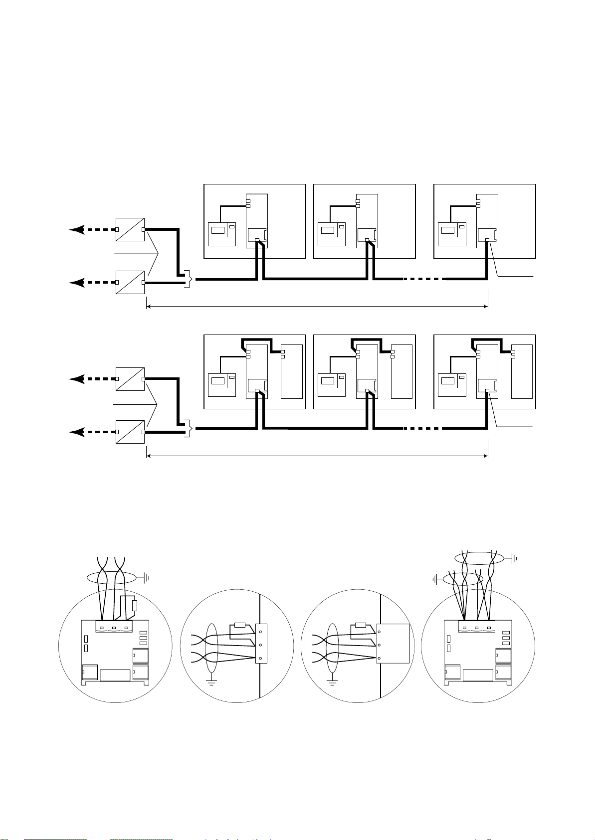
MP2000 AIR CONDITIONERS
Sistema di controllo a microprocessore per condizionatori d'aria •
Air conditioners microprocessor control system
Collegamento seriale con protocollo di comunicazione MODBUS - JBUS per massimo 16 unità collegate in
multipunto.
Collegamento con GATEWAY-MODBUS per la traduzione
del protocollo RC-Com in MODBUS/JBUS e connessione
ad un supervisore locale.
Estensione complessiva massima della linea seriale 1.200m.
GATEWAY - MODBUS
RS485
RS232
MODBUS/JBUS protocol
Protocollo MODBUS/JBUS
GATEWAY - MODBUS
GATEWAY - MODBUS
RS485
Inizio linea
Start line
RS485
RS485
RS485
UNITA' 1 •
TERMINAL
Protocollo RC-com
RC-com protocol
UNITA' 1 •
UNIT 1
BOARD
A
UNIT 1
BOARD
A
RS485
MAX 1.200m
BOARD
B
Serial connection with MODBUS - JBUS communication protocol for max 16 units in multipoint connection.
Connection with GATEWAY-MODBUS for RC-com protocol translation into MODBUS/JBUS protocol and connection to a local supervision system.
Max length of the serial line 1.200m.
UNITA' 2 •
TERMINAL
UNITA' 2 •
UNIT 2
BOARD
A
UNIT 2
BOARD
A
RS485
MAX 16 UNITA'
MAX 16 UNITS
BOARD
B
UNITA' 16 •
TERMINAL
UNITA' 16 •
UNIT 16
BOARD
A
UNIT 16
BOARD
A
RS485
Fine linea
End line
BOARD
B
RS232
MODBUS/JBUS protocol
Protocollo MODBUS/JBUS
GATEWAY - MODBUS
Inizio linea
Start line
RS485
TERMINAL
Protocollo RC-com
RC-com protocol
Fig. 24
Connessione tra MP2000 e GATEWAY
Connessione tra MP2000 e SUPERVISORE
Per la connessione è necessario prevedere una resistenza
terminale di 120Ω all'inizio ed alla fine della linea.
COPPIA 1
PAIR 1
GND RX+
TX+
COPPIA 2
PAIR 2
RXTX-
120Ω
120Ω
RX-
5
TX-
4
RX+
TX+
1
GND
RS485
MAX 1.200m
TERMINAL
RS485
TERMINAL
MAX 16 UNITA'
MAX 16 UNITS
RS485
Fine linea
End line
Connection between MP2000 and GATEWAY
Connection between MP2000 and SUPERVISOR
Ω
For the connections it is necessary to install a 120
terminal
resistance at the beginning and at the end of the line.
120Ω
RX- / TX-
RX+ / TX+
GND
GND RX+
TX+
RXTX-
Connessione di fine linea
Connection of end line
Connessione Gateway (inizio linea)
Gateway connection (start line)
Fig. 25
Per il GATEWAY e le relative connessioni fare riferimento
al relativo manuale di istruzione.
RC GROUP - 149_ItEn.0102
Connessione Supervisore (inizio linea)
Supervisor connection (start line)
Come doppiare i cavi
How to twin the cables
For the GATEWAY connections please refer to the relative
instruction manual.
25
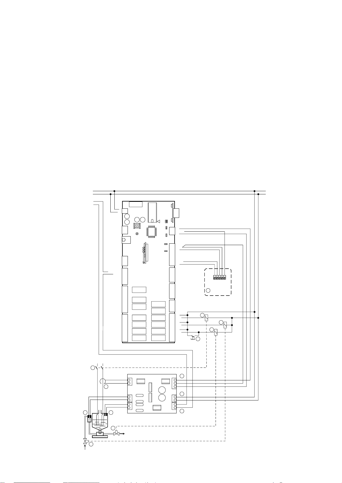
MP2000 AIR CONDITIONERS
Sistema di controllo a microprocessore per condizionatori d'aria •
Air conditioners microprocessor control system
CONNESSIONE SISTEMA DI UMIDIFICAZIONE
Il sistema di umidificazione prevede i seguenti collegamenti:
1 Collegamento della sonda combinata di temperatura/
umidità alla BOARD "A".
2 Collegamento alimentazione elettrica della scheda
umidificatore.
3 Collegamento trasformatore amperometrico di corrente
umidificatore alla scheda umidificatore.
4 Collegamento sensore di conducibilità acqua alla
scheda umidificatore.
5 Collegamento sensore di livello acqua alla scheda
umidificatore.
6 Collegamento uscita digitale livello acqua dalla scheda
umidificatore alla scheda BOARD "A" (24Vac).
7 Collegamento uscite analogiche di conducibilità acqua
e corrente umidificatore dalla scheda umidificatore alla
scheda BOARD "A".
8 Pulsante per scarico acqua manuale.
9 Relè per comando scarico acqua.
10 Relè per comando carico acqua.
11 Teleruttore umidificatore.
24V
24V
RX/TX-
RX/TX+
ID11-230Vac
ID11-24Vac
ID11-R
----------ID12-R
ID12-24Vac
ID12-230Vac
NO11
NC11
NO10
NC10
NO13
GND
VG0
VG1
------
-----NO9
NC9
NO8
-----NO7
-----NO6
------
FUSE
1
G
J17
G0
J11
J19
1
J20
Y1
Y0
1
J21
1
C11
J22
C10
C9
1
C8
C7
J24
C6
C13
K11
K10
K13
J14 = 2-3
J28 = 2-3
J29 = 2-3
K9
K8
K7
K6
K1
K2
K3
K4
K5
K12
J9 J8
J29
J28
HUMIDIFICATION SYSTEM CONNECTION
The humidification system needs the following connections:
1 Connection of the combined temperature/humidity sen-
sor to BOARD "A".
2 Connection of the electric feeding for the humidifier
card.
3 Connection of the humidifier amperometric transformer
to the humidifier card.
4 Connection of the water conductivity sensor to the
humidifier card.
5 Connection of the water level sensor to the humidifier
card.
6 Connection of the water level digital output from hu-
midifier card to BOARD "A" (24Vac).
7 Connection of the water conductivity and humidifier
current analog outputs from humidifier card to BOARD
"A".
8 Push button for manual water drain
9 Relay for water drain
10 Relay for water fill
11 Humidifier contactor
RS485
3
3
2
2
1
1
3
2
1
B8
J1
+24Vdc
B7
3
1
2
1
J15
321
B6
AVSS
J14
B5
321
B4
AVSS
J2
B3
B2
AVSS
B1
1
IDCM2
ID10
ID9
J3
ID8
ID7
1
ID6
IDCM1
ID5
ID4
J4
ID3
ID2
ID1
1
C1
NO1
------
J5
C2
NO2
1
C3
NO3
-----C4
NO4
------
J6
C5
NO5
-----C12
NO12
1
11
8
M
+ (G)
H (%rH)
NTC (°C)
NTC (°C)
1
10
9
26
230/400V
11
3
4 5
10
J3
T1
T2
J2
C1
C2
L1
L2
J1
J6
7
B8
G0
B7
J5
2
G
G0
O1
O2
J4
6
9
Fig. 26
RC GROUP - 149_ItEn.0102
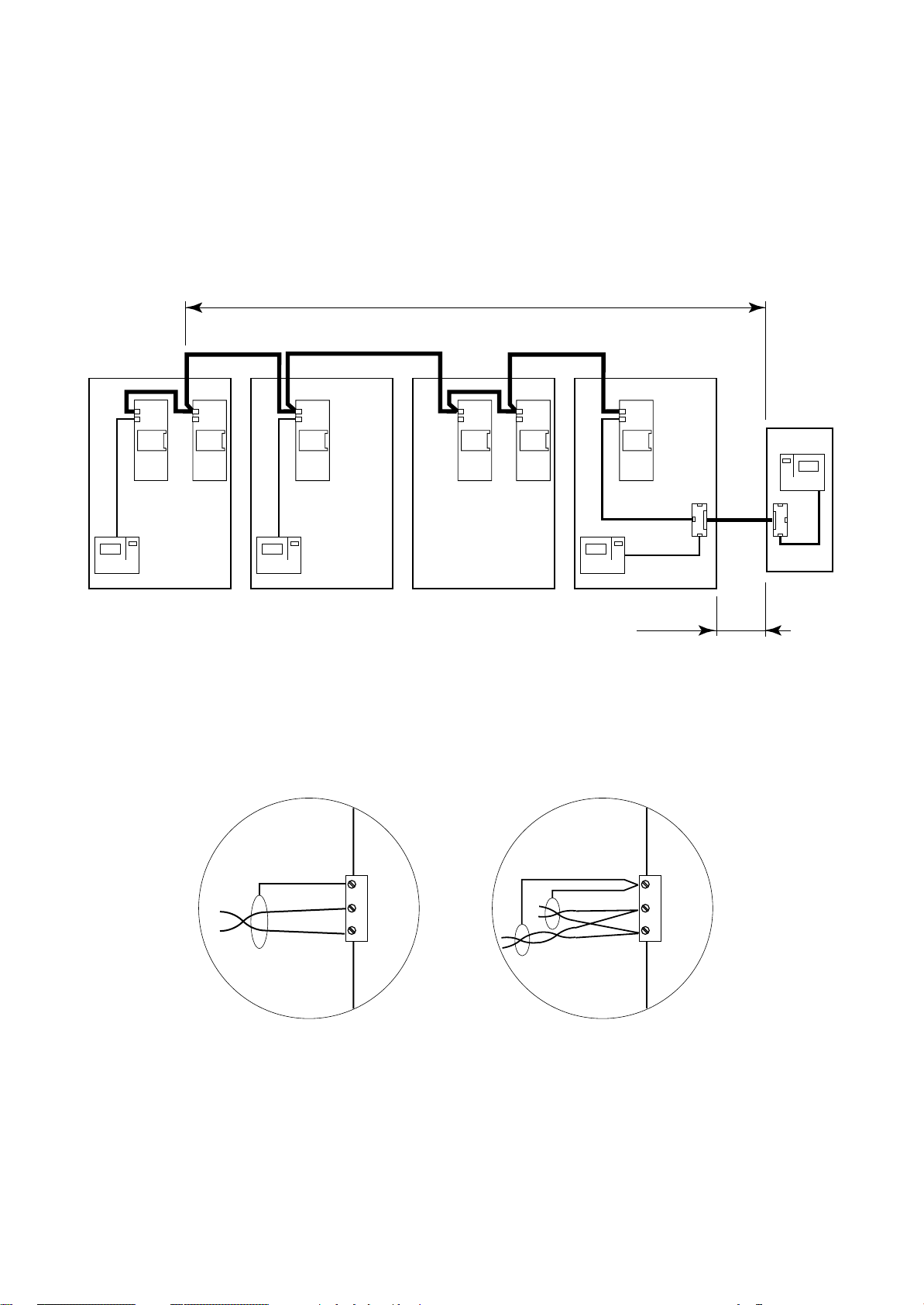
MP2000 AIR CONDITIONERS
Sistema di controllo a microprocessore per condizionatori d'aria •
Air conditioners microprocessor control system
CONNESSIONE RETE LAN
La connessione è a cura del Cliente.
Per questo tipo di collegamento utilizzare un cavo scher-
2
mato ad 1 coppia intrecciata con sezione di 0,5 mm
(tipo
AWG20) da collegarsi al morsetto J11 della scheda BOARD.
ATTENZIONE! Rispettare la polarità; l'RX/TX+ della
scheda deve essere collegato al rispettivo RX/TX+ della
successiva e così anche per l'RX/TX-.
ADDR ADDR ADDR ADDR ADDR
BOARD
UNIT 1
B
BOARD
A
TERMINAL TERMINAL
UNITA' 2 •
UNIT 2
BOARD
TERMINAL
UNITA' 1 •
ADDR
A
LAN CONNECTION
Connection is by Customer care.
For this connection please use a single twisted-pair shielded
cable with section of 0,5mm
cable to the J11 terminal of the BOARD card.
ATTENTION to the polarity; the RX/TX+ of the BOARD
must be connected to the RX/TX+ of the next one and so
on for the RX/TX-.
MAX 500m
BOARDABOARD
UNITA' 3 •
UNIT 3
2
(type AWG20). Connect the
"T" REMOTE
B
BOARD
A
UNITA' 4 •
MAX 200m
T
UNIT 4
TERMINAL
T
Fig. 27
La figura indica una configurazione tipo completa di Terminale Remoto "T" che può anche non essere presente nella
rete LAN.
J11
GND
RX/TX-
RX/TX+
Connessione della scheda
Card connection
Fig. 28
RC GROUP declina ogni responsabilità per una non
corretta esecuzione del collegamento.
In the picture is show a complete configuration with "T"
Remote Terminal that can not be present in a LAN network.
J11
GND
RX/TX-
RX/TX+
Come doppiare i cavi
How to twin the cables
RC GROUP is not responsible for any wrong connection.
RC GROUP - 149_ItEn.0102
27
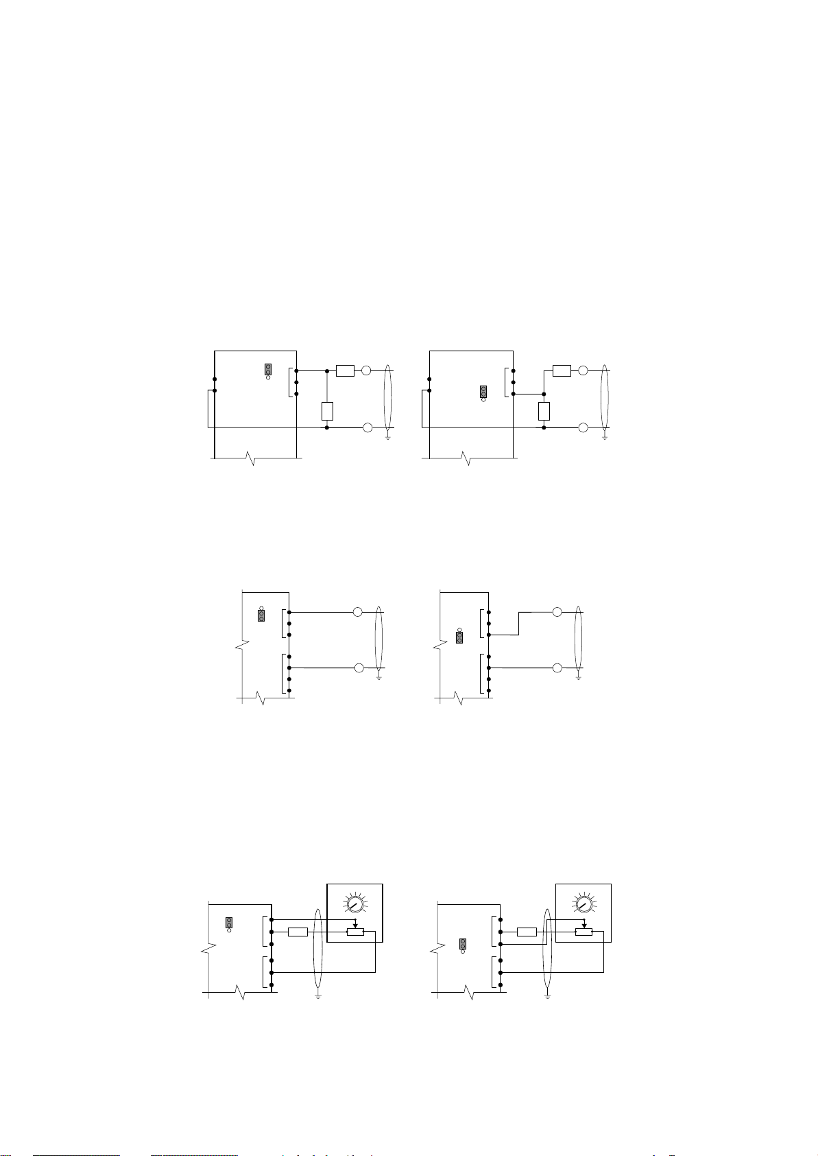
MP2000 AIR CONDITIONERS
Sistema di controllo a microprocessore per condizionatori d'aria •
Air conditioners microprocessor control system
COLLEGAMENTO PER SISTEMA DI COMPENSAZIONE SET POINT TEMPERATURA
La connessione è a cura del Cliente; utilizzare un cavo
schermato ad 1 coppia intrecciata con sezione di 0,5 mm
(tipo AWG20).
Collegamento per sistema di compensazione set point
temperatura automatico (segnale in tensione).
Il segnale di compensazione proviene da un sistema esterno (sonde attive o sistema di supervisione) e può essere
collegato a più unità contemporaneamente.
In base al segnale installare le resistenze da 0,5÷1W, non
fornite, come indicato in figura e predisporre il ponticello
J28 per l'ingresso B7 o il ponticello J29 per l'ingresso B8.
Segnale R1 R2
÷1V -- --
0
0÷5V 330Ω 1300Ω
÷10V 330Ω 3000Ω
0
0÷20V 330Ω 6200Ω
BOARD
G
G0
J29
B8
3
2
1
J1
+
R2
0÷1V
0÷5V
0÷10V
R1
0÷20V
–
Fig. 29
Collegamento per sistema di compensazione set point
temperatura automatico (segnale in corrente).
Il segnale di compensazione proviene da un sistema esterno (sonde attive o sistema di supervisione) e può essere
collegato ad una sola unità.
BOARD
B8
3
J29
2
1
J1
+
0÷20mA
CONNECTION OF THE TEMPERATURE SET POINT
COMPENSATION SYSTEM
Connection is by Customer care.
2
For this connection please use a single twisted-pair shielded
cable with section of 0,5mm
2
(type AWG20).
Connection for automatic temperature set point compensation (voltage signal).
The compensation signal coming from an external system
(active sensor or supervision system) and it is possible a
multipoint connection with more units.
÷
According to the signal type install two 0,5
1W resistances,
not furnished, as shown in the picture and predisposition of
the J28 jumper, for inlet B7, or J29 jumper for inlet B8.
BOARD
G
G0
J28
J1
3
2
1
R2
B7
0÷1V
0÷5V
0÷10V
R1
0÷20V
Signal R1 R2
+
÷
1V -- --
0
0÷5V 330Ω1300
0÷10V 330Ω3000
–
0÷20V 330Ω6200
Ω
Ω
Ω
Connection for automatic temperature set point compensation (current signal).
The compensation signal coming from an external system
(active sensor or supervision system) and it is possible a
single connection with one units.
BOARD
J1
3
J28
B7
2
1
+
0÷20mA
AVSS
J2
–
Fig. 29a
Collegamento per sistema di compensazione set point
temperatura manuale.
Vengono utilizzati un potenziometro da 1KOhm ed una
resistenza da 23KOhm collegati come indicato.
Predisporre il ponticello J28 per l'ingresso B7 o il ponticello
J29 per l'ingresso B8 su 2-3 per segnale in tensione.
Il sistema prevede il collegamento di un potenziometro per
ogni unità.
Fig. 30
24
25
23
BOARD
J29
3
2
1
B8 (0÷1V)
+V
J1
23KΩ 23KΩ
AVSS
J2
26
27
22
2
1KΩ
3
1
Separare quanto più possibile i cavi dei segnali dai
cavi dei carichi induttivi e di potenza per evitare possibili disturbi elettromagnetici.
RC GROUP declina ogni responsabilità per una non
corretta esecuzione del collegamento.
AVSS
J2
–
Connection for manual temperature set point compensation.
Connect a remote 1KOhm potentiometer and a 23Kohm
resistance as per following wiring diagram.
Set the J28 jumper, for inlet B7, or J29 jumper for inlet B8
on 2-3 for voltage signal.
The system provides the connection of one potentimeter
for each unit.
24
25
23
BOARD
J28
+V
J1
B7 (0÷1V)
3
2
1
AVSS
J2
26
27
22
2
1KΩ
3
1
Separate as much as possible the signal cables from
the inductive load and power cables, to avoid any
electromagnetic noise.
RC GROUP is not responsible for any wrong connection.
28
RC GROUP - 149_ItEn.0102
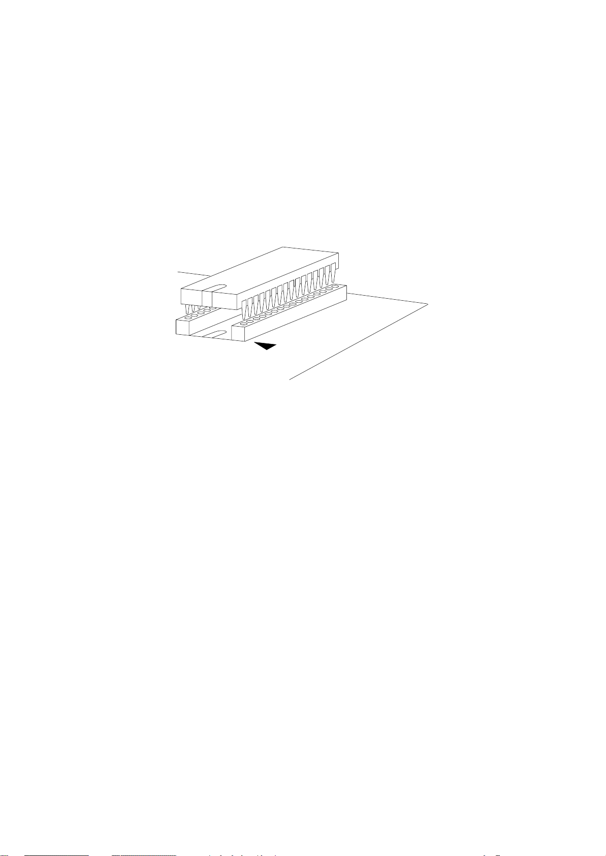
MP2000 AIR CONDITIONERS
Sistema di controllo a microprocessore per condizionatori d'aria •
Air conditioners microprocessor control system
INSERIMENTO DELLA EPROM
Prima di inserire/rimuovere la Eprom togliere l’alimentazione alla scheda.
Per un corretto funzionamento del sistema la Eprom
deve essere inserita nell’apposito zoccolo sulla
BOARD "A" e "B" facendo attenzione che la “tacca”
sulla superficie della Eprom sia nella direzione della
“tacca” di riferimento serigrafata sulla scheda.
Inserire la Eprom sul relativo zoccolo, controllando che
tutti i piedini siano inseriti correttamente nelle loro sedi,
quindi effettuare il MEMORY RESET come indicato nel
relativo capitolo.
INSTALLATION OF THE EPROM
Switch off the system before connecting/disconnecting the Eprom.
When mounting the Eprom into its socket on the
BOARD "A" and "B", pay attention to align the notch on
the surface of the eprom with the corresponding notch
on the socket.
Connect the Eprom into its socket and check that all pins
are correctly inserted, than make the MEMORY RESET as
indicated to the relative chapter.
Fig. 31
Nel rimuovere l’Eprom prestare attenzione a non toccare i
componenti SMD montati sulla scheda nello spazio interno allo zoccolo.
NOTA SU COME MANIPOLARE LE EPROM E LE SCHEDE ELETTRONICHE
I danneggiamenti elettrici che si verificano sui compo-
nenti elettronici avvengono quasi sempre a causa delle
scariche elettrostatiche indotte dall’Operatore.
È quindi necessario adottare adeguati accorgimenti per
queste categorie di componenti, ed in particolare:
• prima di maneggiare qualsiasi componente elettronico o scheda, toccare una messa a terra (una scarica
di 10.000V, tensione molto facile da raggiungere con
l’elettricità statica, produce un arco di circa 1cm).
• i materiali devono rimanere per quanto possibile all’interno delle loro confezioni originali. Utilizzare un imballo antistatico ed evitare di toccare il retro della scheda con le mani.
• evitare nel modo più assoluto di utilizzare sacchetti in
plastica, polistirolo o spugne non antistatiche.
• estrarre dalle confezioni antistatiche originali solo una
Eprom alla volta.
• evitare di toccare con le mani i piedini dell’Eprom, afferrando il componente sulle zone che ne sono prive.
When removing the Eprom do not touch the SMD electronic components mounted on the board in the internal
space of the socket. Don’t touch them with any hardware
tool.
NOTE ON HOW USING THE EPROM AND THE ELECTRONIC CARDS
Electrical damages of the electronic components are
usually due to electrostatic charges induced by the Operator.
It is therefore necessary to pay attention to these components and specially to following:
• before using any electronic component or card, touch a
ground reference (a discharge of 10.000V, very common
due to the static electricity, causes an arc of about 1cm).
• materials should be left as long as possible inside their
original packaging. Handle the boards carefully, without
touching their rear part with the hands.
• do not use plastic bags, polystyrene or non-antistatic
sponges.
• take out of the original antistatic packaging one Eprom at
a time.
• do not touch the pins of the Eprom.
RC GROUP - 149_ItEn.0102
29
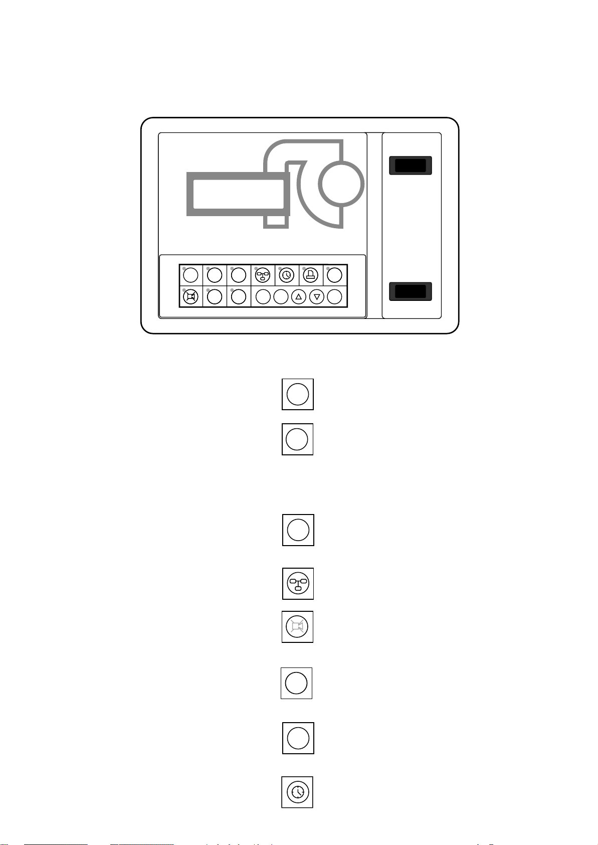
MP2000 AIR CONDITIONERS
Sistema di controllo a microprocessore per condizionatori d'aria •
Air conditioners microprocessor control system
FUNZIONI DELLA TASTIERA E PROGRAMMAZIONE
MP2000
RC GROUP
HOME SET PRG
1
234
MEMO
E
Fig. 32
STATUS
ALARM
567
KEYBOARD FUNCTIONS AND PROGRAMMING
ON/OFF
I ENTER
MAN - O - AUT
SUMMER WINTER
Vengono visualizzate temperatura e umidità ambiente (se presente la sonda), la presenza eventuale di allarmi e lo stato dell’unità.
Visualizzazione del set point di temperatura con
possibilità di variazione. Per variare il set point
premere: tasto ENTER, tasti FRECCIA e tasto
ENTER per conferma dati. Dopo aver inserito
la password e premendo per 3 secondi, è possibile resettare gli allarmi ed attivare la funzione MANUAL.
Dopo aver inserito la password si accede all’elenco dei parametri "SERVICE": set point,
banda di temperatura, pressione, soglie di allarme, allarme generale.
Da un Terminale condiviso permette di accedere ai parametri delle eventuali unità connesse
in rete LAN.
Tacita la suoneria e visualizza l'allarme; premendo un tasto FRECCIA, vengono visualizzati tutti gli allarmi eventualmente presenti.
Vengono visualizzati i valori degli ingressi/uscite analogici e gli stati degli ingressi/uscite digitali. Dopo aver inserito la password, è possibile
calibrare le sonde.
HOME
SET
PRG
ALARM
STATUS
The room temperature and humidity (if the sensor is scheduled), the possible alarms presence
1
and the unit working status are displayed.
The temperature set point is displayed with the
possibility of changing it. To change it press:
2
ENTER key, ARROW key and ENTER key for
data confirmation. After having inserted the password and by pressing for 3 seconds, it is possible to reset the alarms and to activate the
MANUAL function.
After having inserted the password, the list of
"SERVICE" parameters is available: set point,
3
temperature band, pressure, alarm thresholds,
general alarm.
From a shared Terminal, the parameters of the
eventual other units connected in LAN network
4
are displayed.
Switch off buzzer and show the alarm; by pressing an ARROW key the eventual present alarms
5
are displayed.
The analogic inlets/outlets values and the digital
inlets/outlets are displayed. After having inserted
6
the password, it is possible to calibrate the
sensors.
Vengono visualizzati gli ultimi 10 allarmi, le ore
di funzionamento, il numero di avviamenti dei
principali componenti ed è possibile resettare
le ore di funzionamento dei vari contatori.
Permette la visualizzazione/programmazione
dell'orologio datario e la gestione della funzione CHRONO (se presente la scheda CK).
30
MEMO
The last 10 intervened alarms, the working
hours and the number of start-up of the main
7
components are displayed. It is possible to reset
the working hours of the various hourmeters.
By pressing this key, it is possible to display/set
the clock and the CHRONO function managing
(if CK card is present).
RC GROUP - 149_ItEn.0102
 Loading...