


N4032

Stacking Dell Networking Switches: N4032,
N4032F, N4064, N4064F
Dell Engineering
February 2014
A Dell Deployment and Configuration Guide

Date
Description
Author(s)
February 2014
Initial Release
Victor Teeter
Revisions
THIS PAPER IS FOR INFORMATIONAL PURPOSES ONLY, AND MAY CONTAIN TYPOGRAPHICAL ERRORS AND
TECHNICAL INACCURACIES. THE CONTENT IS PROVIDED AS IS, WITHOUT EXPRESS OR IMPLIED WARRANTIES OF
ANY KIND.
© 2014 Dell Inc. All rights reserved. Reproduction of this material in any manner whatsoever without the express written
permission of Dell Inc. is strictly forbidden. For more information, contact Dell.
PRODUCT WARRANTIES APPLICABLE TO THE DELL PRODUCTS DESCRIBED IN THIS DOCUMENT MAY BE FOUND AT:
http://www.dell.com/learn/us/en/19/terms-of-sale-commercial-and-public-sector Performance of network reference
architectures discussed in this document may vary with differing deployment conditions, network loads, and the like. Third party
products may be included in reference architectures for the convenience of the reader. Inclusion of such third party products does
not necessarily constitute Dell’s recommendation of those products. Please consult your Dell representative for additional
information.
Trademarks used in this text:
Dell™, the Dell logo, Dell Boomi™, Dell Precision™ ,OptiPlex™, Latitude™, PowerEdge™, PowerVault™, PowerConnect™,
OpenManage™, EqualLogic™, Compellent™, KACE™, FlexAddress™, Force10™ and Vostro™ are trademarks of Dell Inc. Other
Dell trademarks may be used in this document. Cisco Nexus®, Cisco MDS®, Cisco NX-0S®, and other Cisco Catalyst® are registered
trademarks of Cisco System Inc. EMC VNX®, and EMC Unisphere® are registered trademarks of EMC Corporation. Intel®, Pentium®,
Xeon®, Core® and Celeron® are registered trademarks of Intel Corporation in the U.S. and other countries. AMD® is a registered
trademark and AMD Opteron™, AMD Phenom™ and AMD Sempron™ are trademarks of Advanced Micro Devices, Inc. Microsoft®,
Windows®, Windows Server®, Internet Explorer®, MS-DOS®, Windows Vista® and Active Directory® are either trademarks or
registered trademarks of Microsoft Corporation in the United States and/or other countries. Red Hat® and Red Hat® Enterprise
Linux® are registered trademarks of Red Hat, Inc. in the United States and/or other countries. Novell® and SUSE® are registered
trademarks of Novell Inc. in the United States and other countries. Oracle® is a registered trademark of Oracle Corporation and/or
its affiliates. Citrix®, Xen®, XenServer® and XenMotion® are either registered trademarks or trademarks of Citrix Systems, Inc. in the
United States and/or other countries. VMware®, Virtual SMP®, vMotion®, vCenter® and vSphere® are registered trademarks or
trademarks of VMware, Inc. in the United States or other countries. IBM® is a registered trademark of International Business
Machines Corporation. Broadcom® and NetXtreme® are registered trademarks of Broadcom Corporation. Qlogic is a registered
trademark of QLogic Corporation. Other trademarks and trade names may be used in this document to refer to either the entities
claiming the marks and/or names or their products and are the property of their respective owners. Dell disclaims proprietary
interest in the marks and names of others.
2 Stacking Dell Networking Switches: N4032, N4032F, N4064, N4064F

Table of contents
Revisions ............................................................................................................................................................................................. 2
1 Introduction ................................................................................................................................................................................ 4
1.1 Stacking and management............................................................................................................................................ 5
1.2 Simplified firmware updates for stack members ....................................................................................................... 5
1.3 Dell Networking 8100 Support ..................................................................................................................................... 5
1.4 Stacking and redundancy .............................................................................................................................................. 5
1.5 Nonstop forwarding on the stack ................................................................................................................................ 6
1.6 Hot add/delete and firmware synchronization ......................................................................................................... 6
1.7 Meta-data considerations.............................................................................................................................................. 6
1.8 How a Master is selected ............................................................................................................................................... 7
1.9 How to select a Master during initial stack setup ...................................................................................................... 9
2 Stacking scenarios .................................................................................................................................................................... 11
2.1.1 QSFP+ quad-breakout cables .................................................................................................................................... 12
2.2 Creating a Stack ............................................................................................................................................................ 13
2.2.1 Command-line interface method .................................................................................................................. 14
2.2.2 Web interface method ..................................................................................................................................... 17
2.2.3 Automatic firmware updates for new members joining the stack ........................................................... 21
2.3 Adding new member units to a stack ........................................................................................................................ 23
2.3.1 Command-line interface method .................................................................................................................. 23
2.3.2 Web interface method ..................................................................................................................................... 27
2.4 Updating firmware on a stack ..................................................................................................................................... 31
2.4.1 Command-line interface method .................................................................................................................. 31
2.4.2 Web interface method ..................................................................................................................................... 33
2.5 Removing member units ............................................................................................................................................. 39
2.5.1 Command-line interface method .................................................................................................................. 39
2.5.2 Web interface method ..................................................................................................................................... 45
3 Managing the standby unit ..................................................................................................................................................... 55
3.1.1 Command-line interface method .............................................................................................................................. 55
3.1.2 Web interface method ................................................................................................................................................. 56
4 Appendix A – Commands used in this document ............................................................................................................. 59
5 Appendix B - Network switch versions ............................................................................................................................... 60
3 Stacking Dell Networking Switches: N4032, N4032F, N4064, N4064F
2 864
1 753
10 161412
9 151311
18 242220
17 232119 ACTLNK
19 21 23
20 22 24
17
18
11 13 15
12 14 16
9
10
3 5 7
4 6 8
1
2
ACTLNK
ACT
LNK
ACT
LNK
7 9 151311 17 232119 25 312927 33 393735 41 474543 ACTLNK
1 2
2 864 10 161412 18 242220 26 323028 34 403836 42 484644
ACT
LNK
ACT
LNK
1 2
7
4 6 82
11 13 15
12 14 16
9
10
43 45 47
44 46 48
41
42
ACTLNK19 21 23
20 22 24
17
18
27 29 31
28 30 32
25
26
35 37 39
36 38 40
33
34
1 Introduction
Most Dell switches today include a stacking feature that allows multiple switches to operate as a single
unit. These stacks include up to twelve Dell Networking N4032/N4032F/N4064/N4064F switches in any
combination, using up to four links between stack members. Any Ethernet port type on the front panel
can be used in creating these links, including SFP+, QSFP+, and 10GbaseT.
A single switch in the stack (known as the Master switch) manages all the units in the stack using a single
IP address, which allows the user to access every port in the stack from this one address. This IP address is
copied from the Master to the Standby when the Standby is created. If for any reason the Master fails, the
Standby takes over as Master keeping the IP address of the stack the same. This allows continuous
management of the stack.
The
new
Master unit also continues to use the
disruptions to the network. When a failed Master re-joins the stack, it does so as a member (not a Master)
unless a new Master has not had time to be elected.
Note: Dell N4032, N4032F, N4064, and N4064F series switches can be mixed in any combination within
a stack.
original Master
unit’s MAC addresses, which helps to reduce
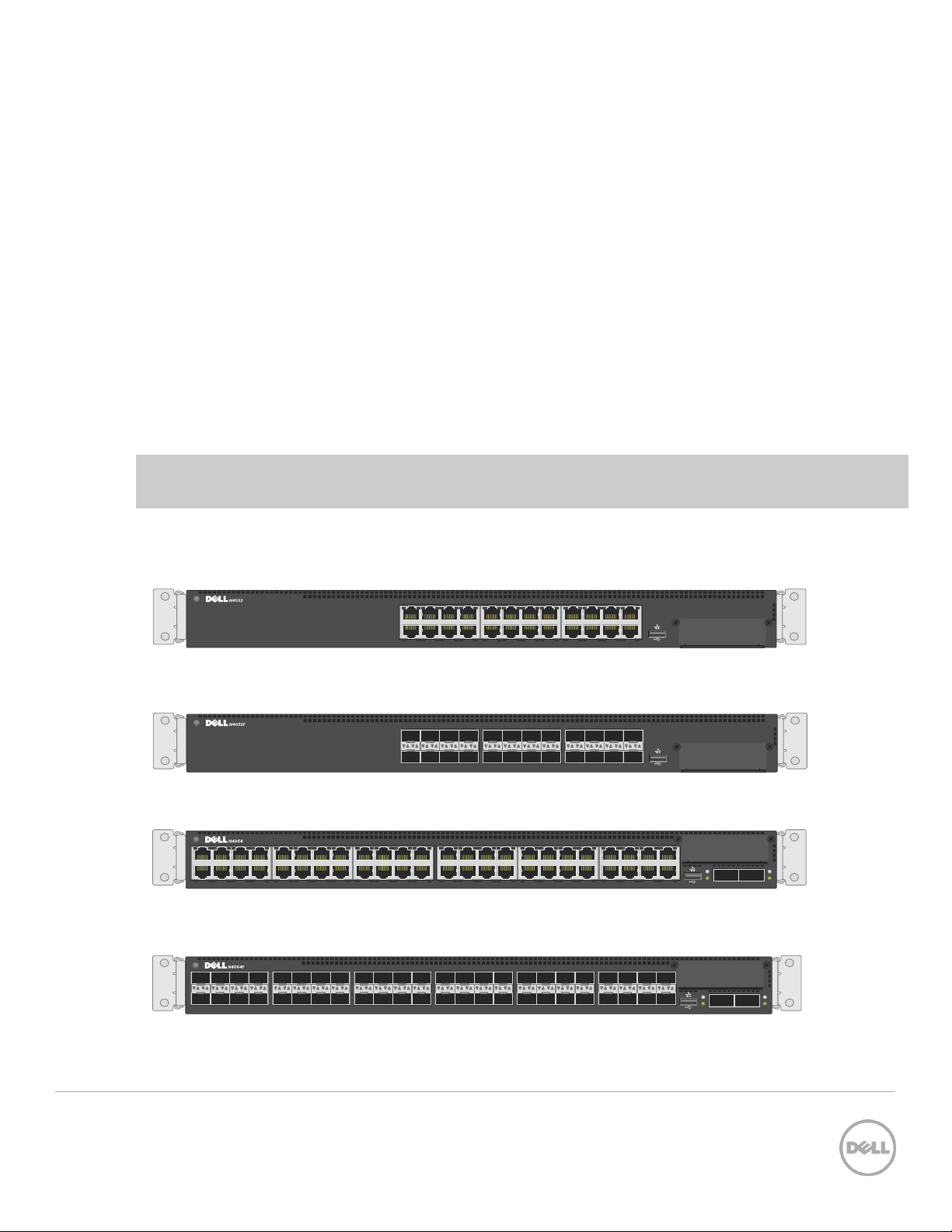
This document provides an easy to use step-by-step guide on how to configure stacking for the Dell
N4032 (Figure 1), N4032F (Figure 2), N4064 (Figure 3) and the N4064F (Figure 4).
Dell N4032 Figure 1
Dell N4032F Figure 2
Dell N4064 Figure 3
Dell N4064F Figure 4
4 Stacking Dell Networking Switches: N4032, N4032F, N4064, N4064F

1.1 Stacking and management
An important advantage of stacking is that it provides a consolidated interface for management of multiple
switches that are linked together. One switch acts as the Master through which the entire stack is
managed through various interfaces (Web, CLI, and SNMP). After a stack is deployed in the network,
operators can easily add units to the stack as their port requirements increase, with minimal administrative
overhead. Additional stack members can immediately use existing configuration information such as
routing and switching configurations, VLANs, ACLs, port profiles, and security certificates.
1.2 Simplified firmware updates for stack members
When switches are stacked, only the Master needs to be updated with new firmware. All other members
of the stack will receive the firmware from the Master at that same time, reducing effort normally required
when updating individual switches. Also, when a switch is added to a stack, if it is running a different
version of firmware than the active version on the Master, the backup firmware on the new member is
automatically updated to match the Master, the backup version of firmware on the new member is then
activated, and the new member is rebooted.
1.3 Dell Networking 8100 Support
Dell Networking 81xx/81xxF switches can be stacked with Dell Networking N4000 switches, but only if all
switches in the stack are running 6.0.0.8 firmware or later, and all switches in the stack are running the
same firmware revision. The firmware must be applied to the switches before they are added to the stack.
Dell Networking N4000 switches cannot be downgraded to 5.x.x.x releases like the 81xx can. Refer to the
N4xxx Release Notes for more information.
1.4 Stacking and redundancy
By connecting a cable from the last switch in a stack back to the first switch, the operator makes sure that
a stack has the protection of redundant paths for control and data traffic, including support for Link
Aggregation Group (LAGs) configured across multiple switches. This means that any single point of failure
(a switch or a stack cable failure) does not affect the overall operation of the remaining stack elements.
This type of topology is known as a ring, or loop topology. Without the final cable(s) connecting the two
ends of the stack, the topology is a daisy-chain, which can cause multiple masters and ip address conflicts
on the network when a middle switch or link goes down. It is therefore recommended to always use a
ring topology when stacking.
Note: Ring topologies are highly recommended for resiliency and fault tolerance over the daisy-chain.
5 Stacking Dell Networking Switches: N4032, N4032F, N4064, N4064F
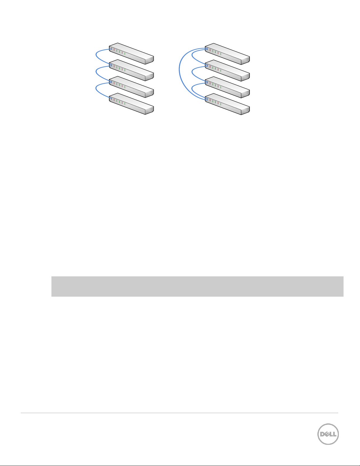
Daisy Chain topology
Ring (loop) topology
1.5 Nonstop forwarding on the stack
The Nonstop Forwarding (NSF) feature allows the forwarding plane of stack units to continue to forward
packets while the control and management planes restart as a result of a power failure, hardware failure,
or software fault on the stack Master and allows the standby switch to quickly takeover as the Master.
1.6 Hot add/delete and firmware synchronization
Units can be added and removed to and from the stack without cycling the power on the stack. When
adding a unit, the Stack Firmware Synchronization feature automatically synchronizes the firmware version
with the version running on the stack Master. The synchronization operation may result in either an
upgrade or a downgrade of firmware on the mismatched stack member. In addition, the running-config
on the member is updated to match the Master switch. The startup-configurations on the standby and
member switches are not updated to match the Master switch. The hardware configuration of every
switch is updated to match the Master switch (unit number, slot configuration, stack member number, and
so on).
Note: Auto-downgrade of a stack is enabled by default. To avoid accidentally downgrading a stack, be
sure to disable auto-downgrade (CLI command: no boot auto-copy-sw allow-downgrade)
1.7 Metadata considerations
When creating a stack, the configuration information is metadata that is part of the hardware configuration
applied at boot time before the switch firmware is started (and before the startup configuration is read).
The stack information shown in the startup and running configurations is simply copies of the stack
configuration for the user’s knowledge. The actual stack information used by the switch
is stored in the startup configuration.
A
stack member
the configuration that says
Since these are stack-capable devices, an un-stacked device is still considered a stack of one. Here is an
example configuration of a device that is
6 Stacking Dell Networking Switches: N4032, N4032F, N4064, N4064F
configuration is always present on stacking capable switches, so there always is a line in
stack
and a second line that says
not
stacked.
member
is not
that which
even if there are no devices stacked.

console#show run
!Current Configuration:
!System Description "N4064F, 6.0.1.3, Linux 2.6.32.9”
!System Software Version 6.0.1.3
!Cut-through mode is configured as disabled
!
configure
slot 1/0 5 ! N4064F
slot 1/1 8 ! Dell 10GBase-T Card
stack
member 1 4 ! N4064F
exit
interface out-of-band
ip address 172.25.194.24 255.255.0.0 172.25.194.254
exit
interface vlan 1
exit
username "admin" password dec68e453164a2 privilege 15 encrypted
line telnet
enable authentication enableList
exit
snmp-server engineid local 800002a203001ec9ddad5b
exit
Notice there is only
then there would be multiple member lines in the configuration, such as:
stack
member 1 1 ! N4064F
member 2 2 ! N4064F
member 3 3 ! N4032F
Note: A single stack member configuration is always present on stack-capable switches even if they are
not part of an actual stack. The single switch is considered a
one
member line in the configuration. If there were multiple members in the stack
1.8 How a Master is selected
A Master is elected or re-elected based on the following considerations, in order:
1. The switch is currently the Master.
2. The switch has the higher MAC address.
3. A unit is selected as standby by the administrator, and a fail over action is manually initiated or
occurs due to a Master unit failure.
stack of one
.
7 Stacking Dell Networking Switches: N4032, N4032F, N4064, N4064F

Note: The terms Master and Manager/Management Unit are often used interchangeably in regards to
stacking.
In most cases, a switch that is added to an existing stack becomes a stack member, and not the
Management Unit. When a switch is added to the stack, one of the following scenarios takes place
regarding the management status of the new switch:
- If the switch has the Management Unit function enabled but another Master unit is already active, then
the switch changes its configured Management Unit value to disabled.
- If the Management Unit function is unassigned and there is another Management Unit in the system,
then the switch changes its configured Management Unit value to disabled.
- If the Management Unit function is enabled or unassigned and there is no other Management Unit in
the system, then the switch becomes Management Unit.
- If the Management Unit function is disabled, the unit remains a non-Management Unit.
- If the entire stack is powered OFF and ON again, the unit that was the Management Unit before the
reboot remains the Management Unit after the stack resumes operation.
A Unit number for the switch can be manually set. To avoid unit-number conflicts, one of the following
scenarios takes place when adding a new member to the stack:
- If the switch has a unit number that is already in use, then the unit added to the stack changes its
configured unit number to the lowest unassigned unit number.
- If the switch added does not have an assigned unit number, then the switch sets its configured unit
number to the lowest unassigned unit number.
- If the unit number is configured and there are no other devices using the unit number, then the switch
starts using the configured unit number.
- If the switch detects that the maximum number of units already exist in the stack making it unable to
assign a unit number, then the switch sets its unit number to unassigned and does not participate in
the stack.
After the stack is created, the show switch command displays the roles of each switch.
console#show switch
Management Standby Preconfig Plugged-in Switch Code
SW Status Status Model ID Model ID Status Version
--- ---------- --------- ---------- ------------- ---------- --------1 Mgmt Sw Ν4032 Ν4032 ΟΚ 6.0.1.3
2 Stack Mbr Oper Stby N4032F N4032F OK 6.0.1.3
8 Stacking Dell Networking Switches: N4032, N4032F, N4064, N4064F
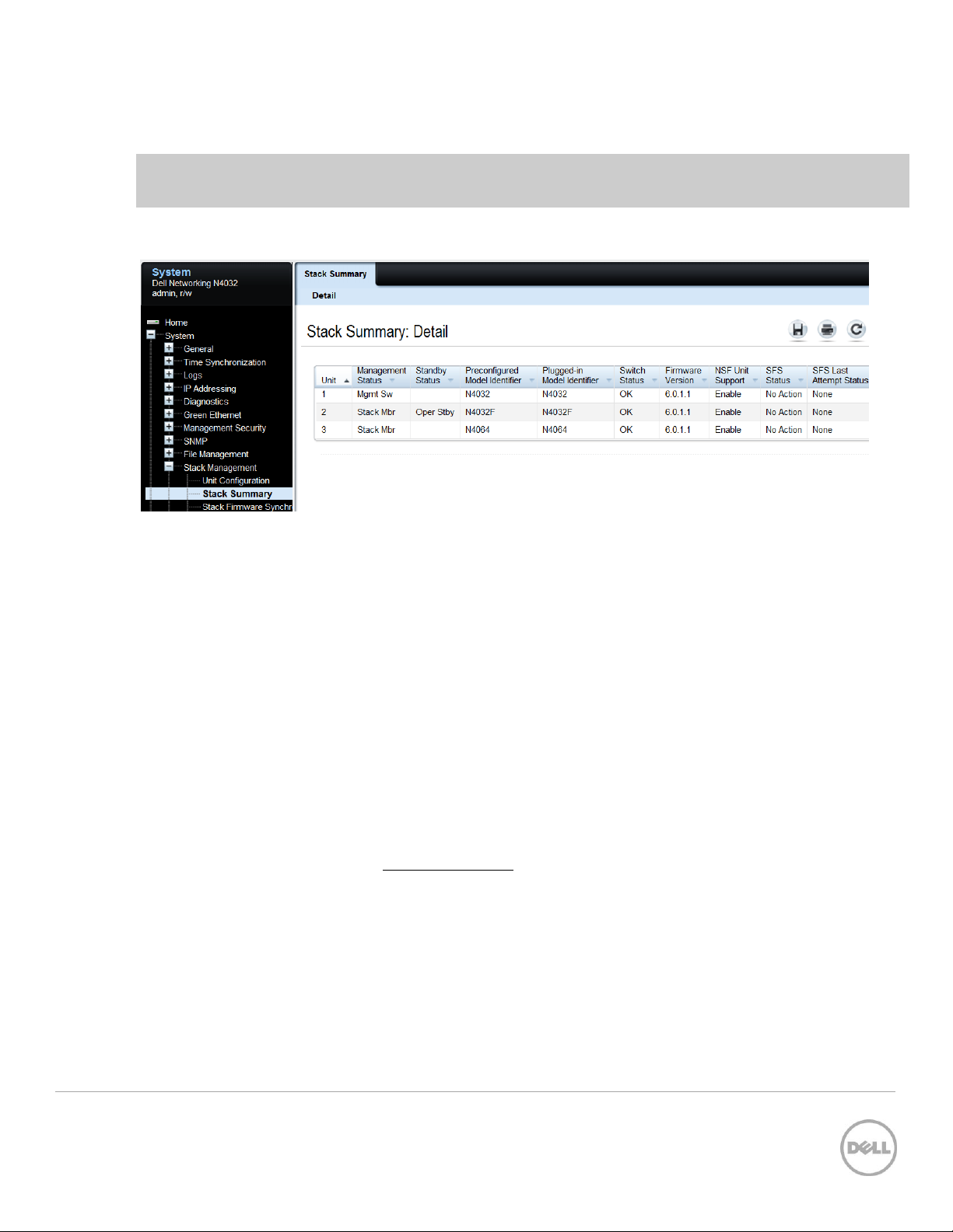
3 Stack Mbr N4064 N4064 OK 6.0.1.3
Note that in this example Switch 1 is the Master (Mgmt Sw) and Switch 2 is the Standby (Oper Stby) ready
to take over as Master in the event the Master fails.
To find the same information from the Web UI go to System > Stack Management > Stack Summary.
1.9 How to select a Master during initial stack setup
After creating a stack it is easy to go into the settings on the Master and select any of the members to take
its place as Master. The former Master becomes a regular stack member automatically.
To select a particular physical unit to be Master during initial setup, simply boot it up
powering on any of the other switches. All subsequent members added to the stack will join as regular
stack members.
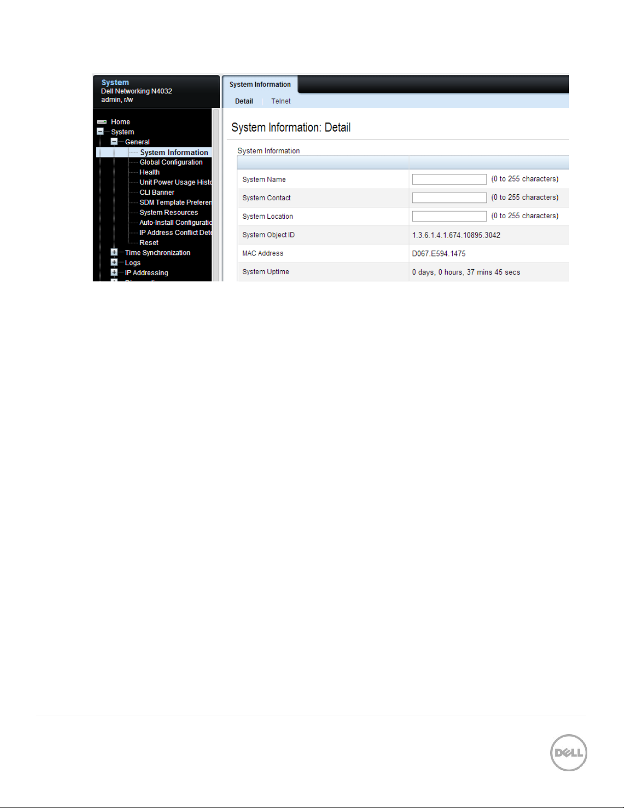
When simultaneously booting two or more switches to initially create a stack, the Master is chosen based
on the highest MAC address. To find the MAC address of an individual switch prior to creating a stack,
type show system from a CLI prompt:
console#show system
System Description: Dell Ethernet Switch
System Up Time: 0 days, 00h:12m:53s
Burned In MAC Address: D067.E594.1475
Or from the Web UI, go to the System > General > System Information page:
completely
before
9 Stacking Dell Networking Switches: N4032, N4032F, N4064, N4064F
10 Stacking Dell Networking Switches: N4032, N4032F, N4064, N4064F
10GBASE -T MODULE
LNK ACT
QSFP+ MODULE
ACT
LNK
ACT
LNK
10G SFP+ MODULE
LNK ACT
2 Stacking scenarios
The following sections present examples in a variety of areas concerning stacking the Dell N4000
switches and provides step-by-step guidance using the CLI and Web UI, with screen shots as a visual
guide. Consult the table of contents above for a list of examples covered in this document.
Each scenario in this document assumes that all Dell switches are using the same firmware revision. It is
also recommended that all devices are using the latest firmware version.
Note: Upgrade the firmware to the latest revision on the units before stacking them.
Unless mentioned otherwise, all scenarios below assume the switches are using the static ports that are
hard-wired into the switches, and that no modules are installed providing additional ports. However, ports
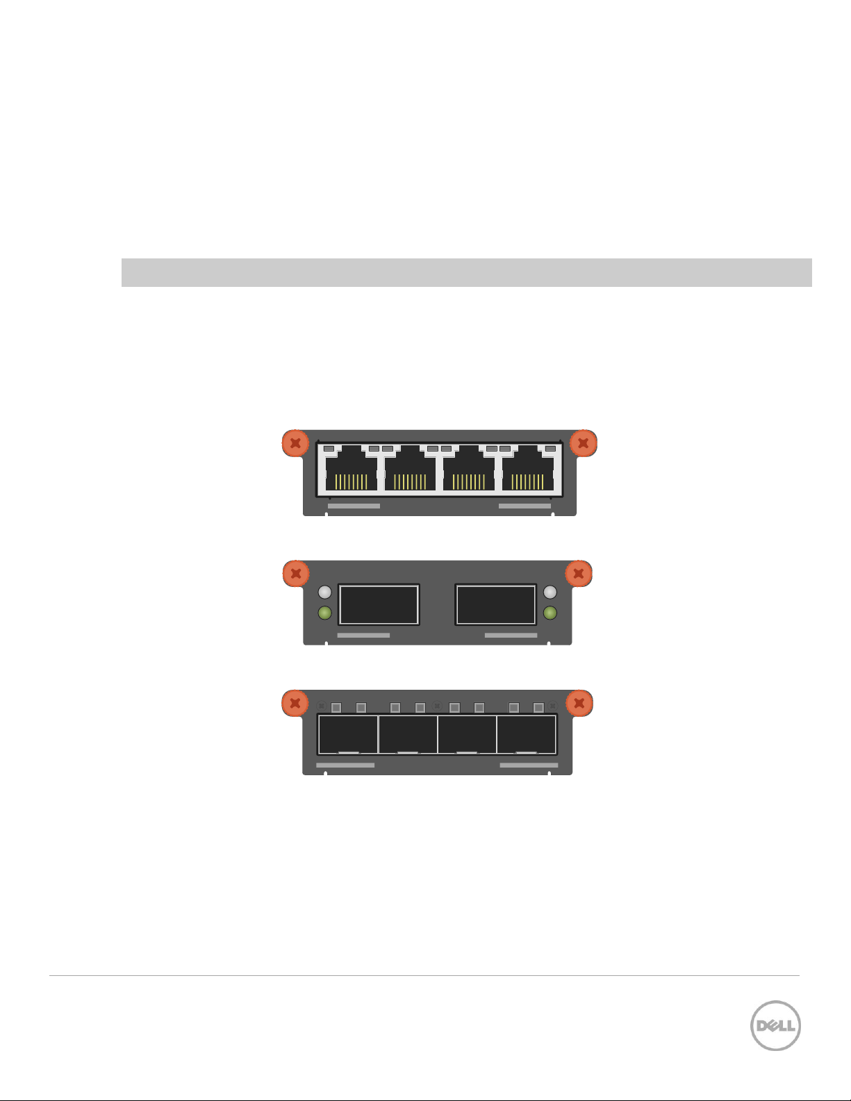
from an installed expansion module are supported and may be used for stacking. The following expansion
modules are supported for stacking in Dell N4000 switches:
10Gbase-T four-port expansion module for the Dell Networking N4xxx and N4xxxF Figure 5
40G QSFP+ two-port expansion module for the Dell Networking N4xxx and N4xxxF Figure 6
10G SFP+ four-port expansion modules for the Dell Networking N4xxx and N4xxxF Figure 7
With an expansion module installed, the command show switch stack-ports shows the link status,
link speed, and stack mode for each port in the module.
11 Stacking Dell Networking Switches: N4032, N4032F, N4064, N4064F
2 864
1 753
10 161412
9 151311
18 242220
17 232119 ACTLNK
QSFP+ MODULE
ACT
LNK
ACT
LNK
19 21 23
20 22 24
17
18
11 13 15
12 14 16
9
10
3 5 7
4 6 8
1
2
ACTLNK
QSFP+ MODULE
ACT
LNK
ACT
LNK
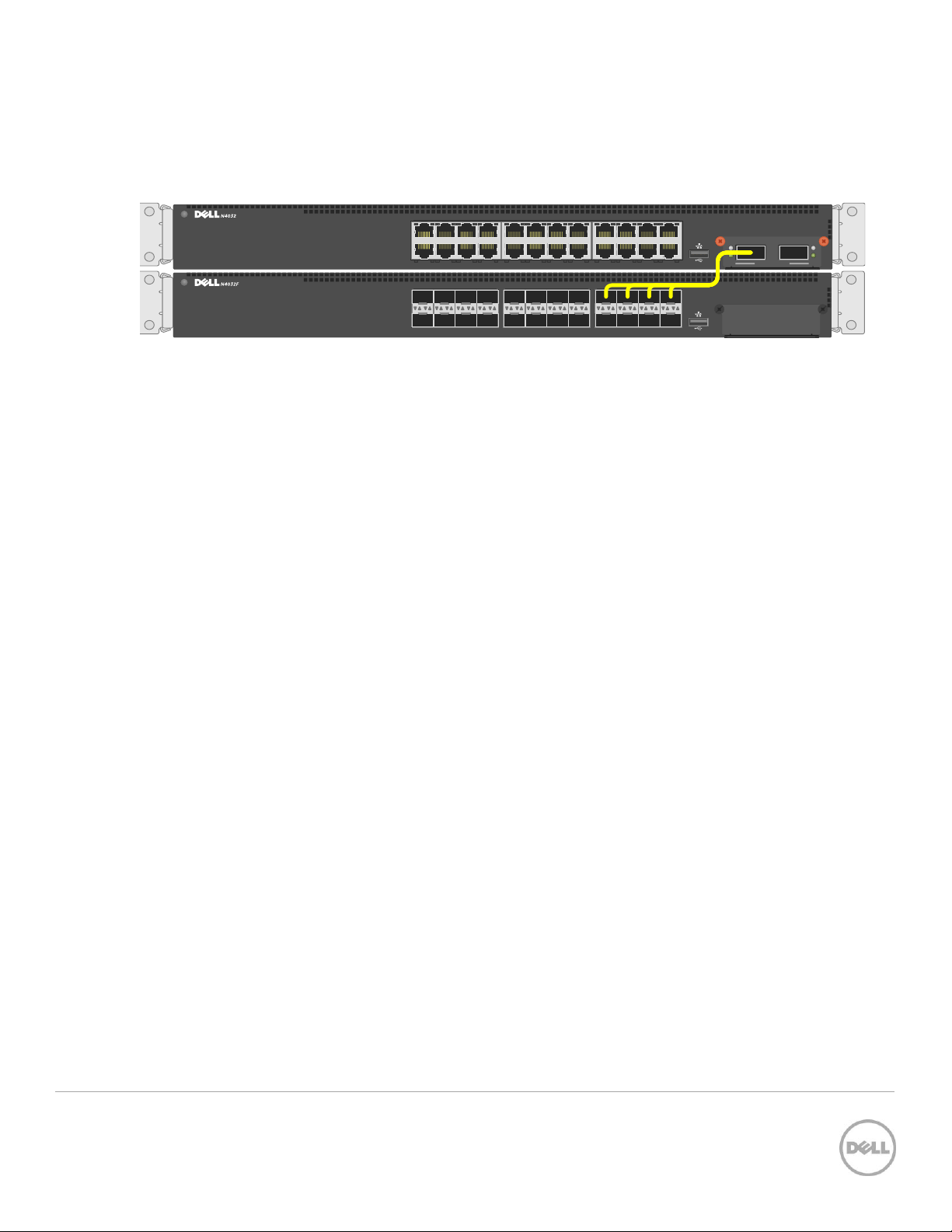
2.1.1 QSFP+ quad-breakout cables
QSFP+ quad-breakout cables may also be used for stacking. This allows a 40G QSFP+ port to connect to
four 10G SFP+ ports on the adjacent switch. When a breakout cable is used, the connections are
considered to be four links taking up four ports.
QSFP+ quad-breakout cable may be used for stacking Figure 8
To use a QSFP+ quad-breakout cable to stack two peers, the QSFP+ port must be set to port mode 4x10G
and reloaded before setting it to stack mode (described in the next section). From the interface
configuration CLI prompt, use the hardware profile command to set the port to this mode. The
command is:
console(config-if-Fo1/0/1)#hardware profile portmode 4x10g
This command will not take effect until the switch is rebooted.
When the portmode changes on a port, so do the interface names. For example, a QSFP+ port may be
named
Fo1/0/1
when in 40G mode but takes on a new identity as
Te1/1/1 through Te1/0/4
when changed
to 10G mode. Therefore, if it is desired to use the QSFP+ quad-breakout cable, be sure to set the port
mode to 4x10G and reload the switch
before
setting the ports to stack mode since configuration settings
on one port mode does not translate to the other portmode.
Also, when in port mode 4x10G it is required that all four of the breakout ports be moved from Ethernet
mode to Stack mode to use them for stacking.
12 Stacking Dell Networking Switches: N4032, N4032F, N4064, N4064F
19 21 23
20 22 24
17
18
11 13 15
12 14 16
9
10
3 5 7
4 6 8
1
2
ACTLNK
QSFP+ MODULE
ACT
LNK
ACT
LNK
2 864
1 753
10 161412
9 151311
18 242220
17 232119 ACTLNK
QSFP+ MODULE
ACT
LNK
ACT
LNK
ACT
LNK
ACT
LNK
7 9 151311 17 232119 25 312927 33 393735 41 474543 ACTLNK
1 2
2 864 10 161412 18 242220 26 323028 34 403836 42 484644
ACT
LNK
ACT
LNK
7 9 151311 17 232119 25 312927 33 393735 41 474543 ACTLNK
1 2
2 864 10 161412 18 242220 26 323028 34 403836 42 484644
ACT
LNK
ACT
LNK
1 2
7
4 6 82
11 13 15
12 14 16
9
10
43 45 47
44 46 48
41
42
ACTLNK19 21 23
20 22 24
17
18
27 29 31
28 30 32
25
26
35 37 39
36 38 40
33
34
ACT
LNK
ACT
LNK
1 2
7
4 6 82
11 13 15
12 14 16
9
10
43 45 47
44 46 48
41
42
ACTLNK19 21 23
20 22 24
17
18
27 29 31
28 30 32
25
26
35 37 39
36 38 40
33
34
2.2 Creating a Stack
Examples below provide steps on how to create a stack. Graphics shown in this section only depict some
of the possibilities of how to cable together members of a stack.
Note: While the cable pictures below come before the configuration steps, it is important not to cable
the stack until instructed to do so.
Cabling is one of the last steps and comes after configuring all switches used in the stack; however, it is
necessary to know exactly each port that is going to be cabled to configure each switch correctly.
The Dell N4000 series switches can be stacked up to twelve high, supporting up to 672x10G ports when
two 40G ports on each unit are configured as stacking ports. The stack can contain any combination of
Dell N4000 and Dell N4000F switches.
Switches can be stacked using anywhere from one to eight Ethernet ports on the front panel, which
includes 40Gb QSFP+ ports, 10Gb SFP+ fiber ports, and 10Gb baseT copper ports. Each of these default
to Ethernet mode and must be reconfigured as stacking ports in order to stack.
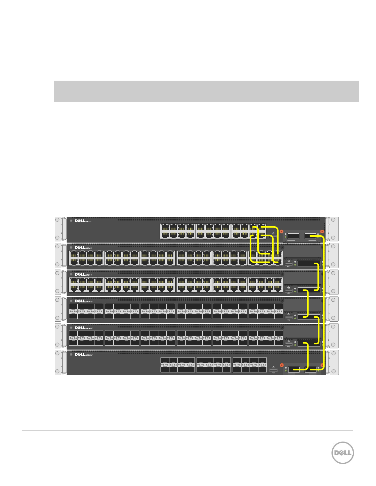
This scenario shows steps to create a stack. Figure 9 shows one example of connectivity between stack
members.
Stacking Dell N4000 series switches using 40G and 10G stack links Figure 9
Notice the top two switches are stacked together using four cables plugged into 10G ports. For each
remaining switch in the stack, one cable from a 40G stacking port on a switch is connected to a 40G
13 Stacking Dell Networking Switches: N4032, N4032F, N4064, N4064F
19 21 23
20 22 24
17
18
11 13 15
12 14 16
9
10
3 5 7
4 6 8
1
2
ACTLNK
ACT
LNK
ACT
LNK
1 2
7
4 6 82
11 13 15
12 14 16
9
10
43 45 47
44 46 48
41
42
ACTLNK19 21 23
20 22 24
17
18
27 29 31
28 30 32
25
26
35 37 39
36 38 40
33
34
ACT
LNK
ACT
LNK
1 2
7
4 6 82
11 13 15
12 14 16
9
10
43 45 47
44 46 48
41
42
ACTLNK19 21 23
20 22 24
17
18
27 29 31
28 30 32
25
26
35 37 39
36 38 40
33
34
stacking port on the next switch. This process is repeated until all of the devices are connected. To
complete the ring topology for the stack, one stacking port on the last switch is connected to a stacking
port on the first switch. See the Ring vs. daisy-chain topology section for more information on ring
topologies.
Things to consider when cabling a stack together:
Only use interfaces with the same bandwidth to stack between members. It is not supported to mix 40G
QSFP+ ports with 10G SFP+ or 10Gbase-T ports on a switch when stacking. It is okay however to use one
interface type between two stack members, then a different interface type between two other stacking
members as shown in Figure 9.
A QSFP+ port is counted as one port when stacking. Therefore if stacking only two switches together, all
QSFP+ ports (including those on an expansion module) can be used to stack between them when in 40G port
mode.
Up to eight ports may be used on any switch for stacking purposes.
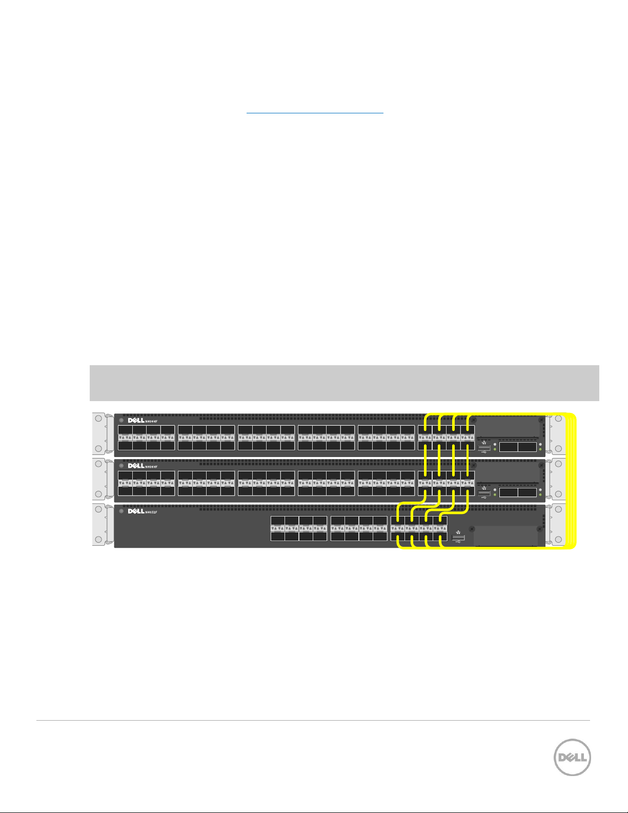
Connecting additional cables in parallel increases the stacking bandwidth. Up to eight ports can be
connected in parallel when only stacking two switches. When stacking three or more switches, up to 4
cables can be connected in parallel between members. It is recommended to have the same bandwidth
between the stack members. It is also recommended to connect the stack in a ring topology for
resiliency. Figure 10 shows an example of connecting four stack ports between each stacking peer.
Note: In a stack of three or more switches, Dell strongly recommends connecting the stack in a ring
topology so that each switch is connected to two other switches.
Stacking Dell N4000/N4000F series switches using multiple stack links Figure 10
2.2.1 Command-line interface method
Make sure all switches are at the same firmware version prior to configuring the stack, or use the Stack
Firmware Synchronization (boot auto-copy-fw) feature to synchronize all firmware during the stack
setup process to that of the Master. The boot auto-copy-fw command is explained below in this
example.
14 Stacking Dell Networking Switches: N4032, N4032F, N4064, N4064F

Connect power to all switches to be stacked. Performing the command show switch stack-ports will
provide information on the unit number for the switch, which is used in the stacking commands. It also
shows Interfaces of the switch that may be used for stacking and whether they are in Ethernet or Stacking
mode.
console#show switch stack-ports
Configured Running
Stack Stack Link Link
Interface Mode Mode Status Speed (Gb/s)
---------- ---------- ---------- ---------- -----------Te1/0/1 Ethernet Ethernet Link Down Unknown
Te1/0/2 Ethernet Ethernet Link Down Unknown
Te1/0/3 Ethernet Ethernet Link Down Unknown
.
.
.
Te1/0/22 Ethernet Ethernet Link Down Unknown
Te1/0/23 Ethernet Ethernet Link Down Unknown
Te1/0/24 Ethernet Ethernet Link Down Unknown
Fo1/1/1 Ethernet Ethernet Link Down 40
Fo1/1/2 Ethernet Ethernet Link Down 40
Te1/1/1 Ethernet Ethernet Detach 10
Te1/1/2 Ethernet Ethernet Detach 10
Te1/1/3 Ethernet Ethernet Detach 10
Te1/1/4 Ethernet Ethernet Detach 10
Te1/1/5 Ethernet Ethernet Detach 10
Te1/1/6 Ethernet Ethernet Detach 10
Te1/1/7 Ethernet Ethernet Detach 10
Te1/1/8 Ethernet Ethernet Detach 10
The example above shows a Dell N4032F with a QSFP+ two-port expansion module installed. The two
40G QSFP+ ports are represented by interfaces
stacking in the example below.
F01/1/1
and
F01/1/2
. We will use these two interfaces for
Notice that Configured Stack Mode and the Running Stack Mode are currently both Ethernet. Perform the
following commands to convert each desired port to Stack mode.
console#config
console(config)#stack
console(config-stack)#stack-port fortygigabitethernet 1/1/1 stack
console(config-stack)#stack-port fortygigabitethernet 1/1/2 stack
console(config-stack)#show switch stack-ports
Configured Running
Stack Stack Link Link
Interface Mode Mode Status Speed (Gb/s)
---------- ---------- ---------- ---------- -----------Te1/0/1 Ethernet Ethernet Link Down Unknown
Te1/0/2 Ethernet Ethernet Link Down Unknown
15 Stacking Dell Networking Switches: N4032, N4032F, N4064, N4064F

Te1/0/3 Ethernet Ethernet Link Down Unknown
.
.
.
Te1/0/23 Ethernet Ethernet Link Down Unknown
Te1/0/24 Ethernet Ethernet Link Down Unknown
Fo1/1/1 Stack Ethernet Link Down 40
Fo1/1/2 Stack Ethernet Link Down 40
The Configured Stack Mode is now
changes to Stack upon reloading the switch, as instructed below.
Save the configuration to the Startup-Configuration.
console#copy running-config startup-config
This operation may take a few minutes.
Management interfaces will not be available during this time.
Are you sure you want to save? (y/n) y
Configuration Saved!
Follow these steps to complete the process:
1. Apply the same method to the remaining switches. Do not forget to configure the stacking ports on
the last and first switch to create a ring topology if desired.
2. Once the switches have been configured,
3. While powered off,
4. Select the switch to be the Master switch and power up that switch only allowing a few minutes to
boot up completely.
5. Verify the switch is up by logging into the CLI.
6. Once the Master is up, power up the second switch in line.
7. Allow the second switch 30 seconds to boot up, then power up the third switch.
8. Continue to power up each switch allowing 30 seconds between powering switches. This allows each
adjacent switch to be active before the next one. Failure to wait may result in another switch
becoming the Master.
cable all of the switches together using the stack ports that were configured.
Stack
, but the Running Stack Mode is still
remove power from all switches
Ethernet
.
. The Running Mode
All subsequent switches will enter the stack as Member Units. Stack Member units serial ports and
management IP addresses are not accessible for managing those devices. Only the Master’s management
ports can be used to monitor and configure ports in the stack.
16 Stacking Dell Networking Switches: N4032, N4032F, N4064, N4064F
2.2.1.1 Validation
After the entire stack is created, it can be validated with the show switch command from the Master
switch:
console#show switch
Management Standby Preconfig Plugged-in Switch Code
SW Status Status Model ID Model ID Status Version
--- ---------- --------- ----------- ----------- -------- ------1 Mgmt Sw N4064F N4064F OK 6.0.1.1
2 Stack Mbr Oper Stby N4064 N4064 OK 6.0.1.1
3 Stack Mbr N4032 N4032 OK 6.0.1.1
The show switch stack-ports command can also be used to see all of the ports that have been added to
the stack as well as which ones are being used for stacking. To view only ports that are configured for
stacking, use the command show switch stack-ports | include Stack.
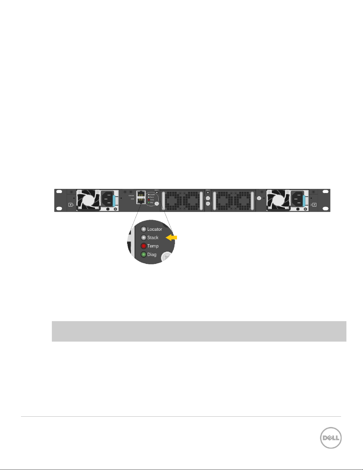
Figure 11 shows the Stack LED that is located on the back panel of every Dell N4000 series switch.
Stacking LED for the Dell N4000/N4000F series switch Figure 11
When the switch is the Master of a stack, the LED glows solid blue. If it is a stack member only, it glows a
solid amber. When in stand-alone mode, the LED is off.
Note: Each stack members’ role (including the Master and Standby) can be defined any time after the
initial stack is created.
2.2.2 Web interface method
Make sure all switches are at the same firmware version prior to configuring the stack, or use the Stack
Firmware Synchronization (boot auto-copy-fw) feature to synchronize all firmware during the stack
setup process to that of the Master. The boot auto-copy-fw command is explained below in this
example.
17 Stacking Dell Networking Switches: N4032, N4032F, N4064, N4064F
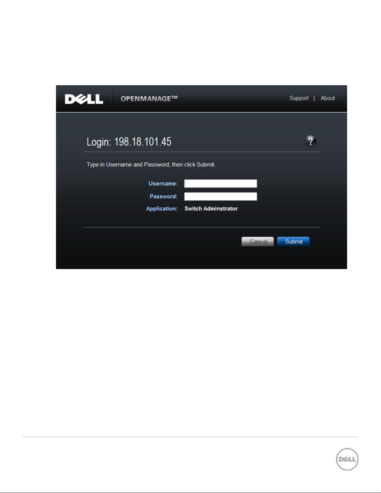
Select a switch to be Master of the stack and for managing all ports and member units with the stack.
Login to the Web UI for this switch by entering the IP address of the switch into a supported Web browser.
A username and password is required and should be setup beforehand on each switch. See the switch
User Guide for more information regarding username, password, and Web access.
After login, the first screen to appear is the Home screen, which shows the current stacking member
number. Before stacking, the single member has the Stack number of 1 (one).
18 Stacking Dell Networking Switches: N4032, N4032F, N4064, N4064F
 Loading...