


 Loading...
Dell Storage MD1400 Enclosures
Hardware Owner's Manual

Notes, Cautions, and Warnings
NOTE: A NOTE indicates important information that helps you make better use of your computer.
CAUTION: A CAUTION indicates either potential damage to hardware or loss of data and tells you how to avoid the problem.
WARNING: A WARNING indicates a potential for property damage, personal injury, or death.
Copyright © 2014 Dell Inc. All rights reserved. This product is protected by U.S. and international copyright and intellectual property laws. Dell™ and the Dell logo are trademarks of Dell Inc. in the United States and/or other jurisdictions. All other marks and names mentioned herein may be trademarks of their respective companies.
2014 - 09
Rev. A00
Contents |
|
1 About your enclosure........................................................................................... |
5 |
Front-panel features and indicators..................................................................................................... |
5 |
Front-bezel features and indicators..................................................................................................... |
6 |
Hard disk drive indicator patterns......................................................................................................... |
7 |
Back-panel features and indicators...................................................................................................... |
8 |
Enclosure Management Module........................................................................................................... |
8 |
Enclosure failover when two EMMs are installed........................................................................... |
9 |
EMM thermal shutdown.................................................................................................................. |
9 |
Power indicator codes........................................................................................................................ |
10 |
Other information you may need....................................................................................................... |
10 |
2 Installing enclosure components.................................................................... |
12 |
Recommended tools........................................................................................................................... |
12 |
Front bezel (optional).......................................................................................................................... |
12 |
Removing the front bezel.............................................................................................................. |
12 |
Installing the front bezel................................................................................................................ |
13 |
Hard disk drives.................................................................................................................................... |
13 |
Safety: Models AMT, E03J, and E04J............................................................................................ |
13 |
Removing a hard disk drive blank................................................................................................. |
13 |
Installing a hard disk drive blank................................................................................................... |
14 |
Removing a hard disk drive........................................................................................................... |
14 |
Installing a hard disk drive............................................................................................................. |
15 |
Removing a hard disk drive from a hard disk drive carrier........................................................... |
15 |
Installing a hard disk drive into a hard disk drive carrier.............................................................. |
16 |
Enclosure Management Module ........................................................................................................ |
16 |
Removing an EMM blank............................................................................................................... |
17 |
Installing an EMM blank................................................................................................................. |
17 |
Removing an EMM......................................................................................................................... |
17 |
Installing an EMM........................................................................................................................... |
18 |
AC power supply unit or cooling fan module.................................................................................... |
19 |
Removing an AC power supply unit or cooling fan module....................................................... |
19 |
Installing an AC power supply unit or cooling fan module......................................................... |
20 |
About DC power supply units............................................................................................................ |
20 |
Power indicator codes.................................................................................................................. |
20 |
DC power supply module back panel features............................................................................ |
22 |
Removing and installing the DC power supply unit..................................................................... |
22 |
Control panel...................................................................................................................................... |
28 |
Removing the control panel......................................................................................................... |
28 |
Installing the control panel........................................................................................................... |
29 |
Backplane............................................................................................................................................ |
29 |
Removing the backplane.............................................................................................................. |
29 |
Installing the backplane................................................................................................................. |
31 |
3 Troubleshooting your enclosure..................................................................... |
32 |
Safety first—for you and your enclosure............................................................................................ |
32 |
Troubleshooting enclosure startup failure......................................................................................... |
32 |
Troubleshooting loss of communication........................................................................................... |
32 |
Troubleshooting external connections.............................................................................................. |
32 |
Troubleshooting power supply unit or cooling fan module............................................................. |
32 |
Troubleshooting enclosure cooling problems.................................................................................. |
33 |
Troubleshooting Enclosure Management Modules.......................................................................... |
34 |
Troubleshooting hard disk drives....................................................................................................... |
34 |
Troubleshooting enclosure connections........................................................................................... |
35 |
Troubleshooting a wet enclosure...................................................................................................... |
35 |
Troubleshooting a damaged enclosure............................................................................................. |
35 |
4 Getting help......................................................................................................... |
37 |
Contacting Dell.................................................................................................................................... |
37 |
Documentation feedback................................................................................................................... |
37 |
1
About your enclosure
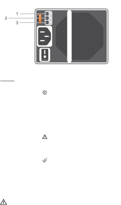
Front-panel features and indicators
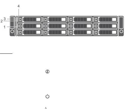
Figure 1. Front-panel features and indicators
Item |
Indicator, |
Icon |
Description |
|
Button, or |
|
|
|
Connector |
|
|
|
|
|
|
1 |
System |
|
The system identification button on the front control panel can |
|
identification |
|
be used to locate a particular enclosure within a rack. When |
|
button |
|
the button is pressed, the system status indicators on the |
|
|
|
control panel and the EMM blink blue until the button is |
|
|
|
pressed again. |
2 |
Power LED |
|
The power LED lights when at least one power supply unit is |
|
|
|
supplying power to the enclosure. |
3 |
Enclosure status |
|
The enclosure status LED glows when the enclosure power is |
|
LED |
|
on. |
|
|
|
Glows solid blue during normal operation. |
|
|
|
Blinks blue when a host server is identifying the enclosure or |
|
|
|
when the system identification button is pressed. |
|
|
|
Blinks amber or remains solid amber for a few seconds and |
|
|
|
then turns off when the EMMs are starting or resetting. |
|
|
|
Blinks amber for an extended time when the enclosure is in a |
|
|
|
warning state. |
|
|
|
Remains solid amber when the enclosure is in the fault state. |
4 |
Hard disk drives |
|
Up to 12 3.5-inch SAS hot-swappable hard disk drives. |
5

Front-bezel features and indicators
Figure 2. Front-bezel features and indicators
Item |
Indicator, Button, or |
Icon |
Description |
|
Connector |
|
|
|
|
|
|
1 |
Enclosure status LED |
|
The enclosure status LED lights when the enclosure |
|
|
|
power is on. |
|
|
|
Lights solid blue during normal operation. |
|
|
|
Blinks blue when a host server is identifying the |
|
|
|
enclosure or when the system identification button is |
|
|
|
pressed. |
|
|
|
Blinks amber or remains solid amber for a few seconds |
|
|
|
and then turns off when the EMMs are booting or |
|
|
|
resetting. |
|
|
|
Blinks amber for an extended time when the enclosure |
|
|
|
is in a warning state. |
|
|
|
Remains solid amber when the enclosure is in the fault |
|
|
|
state. |
2 |
Power LED |
|
The power LED lights when at least one power supply |
|
|
|
unit (PSU) is supplying power to the enclosure. |
3 |
Latch |
|
The latch is used to remove the bezel from the |
|
|
|
enclosure. |
6
Hard disk drive indicator patterns
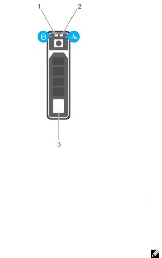
Figure 3. Hard disk drive indicators |
|
|
|
1. |
hard disk drive activity indicator (green) |
2. |
hard disk drive status indicator (green and |
|
|
|
amber) |
3.hard disk drive
Hard disk drivestatus indicator pattern (RAID |
Condition |
Only) |
|
|
|
Blinks green two times per second |
Identify hard disk drive or preparing for removal |
Off |
Hard disk drive ready for insertion or removal |
|
NOTE: The hard disk drive status indicator |
|
remains off until all hard disk drives are |
|
initialized after system power is turned on. |
|
Hard disk drives are not ready for insertion or |
|
removal during this time. The Dell PowerEdge |
|
RAID controller PERC H830 and 12Gb SAS |
|
HBA may take up to a minute to discover and |
|
initialize all the hard disk drives. |
Blinks green, amber, and off |
Hard disk drive predicted failure |
Blinks amber four times per second |
Hard disk drive failed |
Blinks green slowly |
Hard disk drive rebuilding |
Steady green |
Hard disk drive online |
7
Hard disk drivestatus indicator pattern (RAID |
Condition |
Only) |
|
|
|
Blinks green for three seconds, amber for three |
Rebuild aborted |
seconds, and turns off in six seconds. |
|
Back-panel features and indicators
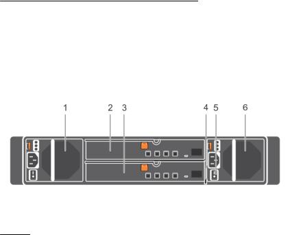
Figure 4. Back-panel features and indicators
Item |
Indicator, Button, or Connector |
Description |
|
|
|
1 |
Power supply unit or cooling fan |
600 W power supply. |
|
module (PS1) |
|
|
|
For more information, see Power indicator codes. |
2 |
Primary enclosure management |
The EMM provides: |
|
module (EMM 0) |
• a data path between the enclosure and the host server. |
|
|
|
3 |
Secondary EMM (EMM 1) |
• enclosure management functions for your enclosure. |
4 |
Information tag |
A slide-out label panel, which allows you to record Service |
|
|
Tag. |
5 |
Power switches (2) |
The power switch controls the power supply output to the |
|
|
enclosure. |
6 |
Power supply unit or cooling fan |
600 W power supply. |
|
module (PS 2) |
|
|
|
For more information, see Power indicator codes. |
Enclosure Management Module
Each EMM provides the following data path and enclosure management functions for your enclosure:
•Monitoring and controlling enclosure environment elements such as temperature, fan, power supply units, and enclosure LEDs.
•Controlling access to hard disk drives.
•Communicating enclosure attributes and states to the host server.
8
NOTE: At least one EMM must be installed in the enclosure. If only one EMM is installed in the enclosure, it must be installed in the primary EMM bay and a blank must be installed in the secondary EMM bay. See Installing an EMM blank .
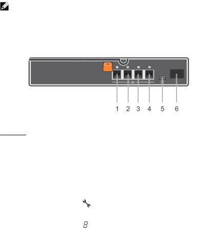
Figure 5. Enclosure Management Module
Item |
Indicator, |
Icon |
Description |
|
Button, or |
|
|
|
Connector |
|
|
|
|
|
|
1,2,3,4 |
SAS port (Input or |
|
Provides SAS connections for cabling the host or an upchain |
|
Output) |
|
expansion enclosure and to the next down chain expansion |
|
|
|
enclosure in a daisy chain.(Single Port, Redundant, and Multi- |
|
|
|
chain Configuration) |
5 |
USB Mini-B (serial |
|
For engineering use only. |
|
debug port) |
|
|
6 |
7-Segment |
|
Display the enclosure location in SAS Chain. |
|
Display |
|
|
Enclosure failover when two EMMs are installed
If two EMMs are installed, a certain degree of failover is offered. Control and monitoring of the enclosure elements can be transferred from one EMM to another in the event of an EMM failure. A failover occurs whenever network communication is ended between an EMM and its peer.
In the event of a peer EMM failure, the surviving EMM activates the amber status LED of the failed EMM. The surviving EMM then takes over the responsibility of enclosure management, which includes monitoring and control of the enclosure LEDs, power supply units, and fans.
EMM thermal shutdown
If critical internal temperatures are reached, the enclosure turns off automatically through either a thermal shutdown command issued by the EMM firmware or through a command from Dell OpenManage Server Administrator.
9
Power indicator codes
Figure 6. Power indicator codes
Item |
LED |
Icon |
Color |
State |
|
|
|
|
|
1 |
DC power |
|
Green |
• ON — Normal operation. Power supply is connected |
|
|
|
|
to DC power and the power switch is on. The power |
|
|
|
|
supply module is supplying DC power to the array. |
|
|
|
|
• OFF — Indicates any one of the following: |
|
|
|
|
– The power switch is off. |
|
|
|
|
– The power supply module is not connected to |
|
|
|
|
power. |
|
|
|
|
– There is a fault condition. |
2 |
Power supply |
|
Yellow |
• ON — Fault detected. |
|
module fault |
|
|
• OFF — OK. |
|
|
|
|
• Blinks briefly when power is first turned on to the |
|
|
|
|
power supply module. |
3 |
AC power |
|
Green |
• ON — Power supply module is connected to a |
source of AC power irrespective of whether or not a power switch is on.
• OFF — Power supply module is completely disconnected from any source of AC power.
Other information you may need
WARNING: See the safety and regulatory information that shipped with your system. Warranty information may be included within this document or as a separate document.
•The rack documentation included with your rack solution describes how to install your system into a rack.
•The Getting Started Guide provides an overview of system features, setting up your system, and technical specifications.
10
•The OpenManage Server Administrator documentation provides information about managing your storage solution using the storage management service within the server administrator.
•The Dell PowerEdge RAID Controller (PERC) H830 and Dell 12Gb SAS HBA User’s Guide provides information about configuring RAID.
•Any media that ships with your system that provides documentation and tools for configuring and managing your system, including those pertaining to the operating system, system management software, system updates, and system components that you purchased with your system.
NOTE: Always check for updates on dell.com/support/manuals and read the updates first because they often supersede information in other documents.
11

2
Installing enclosure components
Recommended tools
You may need the following items to perform the procedures in this section:
•Key to the system keylock
•#2 Phillips screwdriver
•Wrist grounding strap
Front bezel (optional)
Removing the front bezel
1.Using the system key, unlock the front bezel (if locked).
2.Lift the release latch next to the keylock.
3.Pull the left end of the bezel away from the front panel.
4.Unhook the right end of the bezel and pull the bezel away from the system.
Figure 7. Removing and installing the front bezel
1. |
keylock |
2. |
front bezel |
12
Loading...