


 Loading...
Dell™ Networking™ X1000
and X4000 Series Switches
Getting Started Guide
Panduan Pengaktifan

Dell™ Networking™ X1000
and X4000 Series Switches
Getting Started Guide
Regulatory Models: X1008, X1008P, X1018, X1026, X4012, X1018P, X1026P, X1052, X1052P

Notes, Cautions, and Warnings
NOTE: A NOTE indicates important information that helps you make better use of your device.
CAUTION: A CAUTION indicates either potential damage to hardware or loss of data and tells you how to avoid the problem.
WARNING: A WARNING indicates a potential for property damage, personal injury, or death.
____________________
Copyright © 2014 Dell Inc. All rights reserved. This product is protected by U.S. and international copyright and intellectual property laws.
Dell™ and the Dell logo are trademarks of Dell Inc. in the United States and/or other jurisdictions. All other marks and names mentioned herein may be trademarks of their respective companies.
P/N RF9YW |
Rev. A00 |
Welcome
This document provides basic information to install and start running the following Dell Networking X-series switches: X1008/X1008P, X1018/X1018P, X1026/X1026P, X1052/X1052P and X4012.
The switch is delivered from the factory in Unmanaged Mode to avoid unauthorized access to the switch. To use the switch in Managed Mode, press the Mode button for at least seven seconds. The MGMT LED will illuminate when in Managed Mode. To switch back to Unmanaged Mode, repeat the process.
These Dell networking devices are ideal for the small to medium business that requires high performance network connectivity along with advanced web management features. The management features are designed to minimize administrative management effort, while enhancing and improving network traffic control.
For the latest documentation and software updates, go to dell.com/support.
Safety Environmental and Regulatory Information (SERI) is included in the printed documentation.
Package Contents
While unpacking the device, make sure that the following items are included:
•The ordered network switch
•AC power cable (and power brick only for the X1008 and X1008P)
•Console micro-USB serial cable
•Self-adhesive rubber pads (for desk or shelf installation on select systems)
•Installation kit
•Safety Environmental and Regulatory Information document
•Placemat
•This Getting Started Guide
Getting Started Guide |
|
3 |
|

X1000 and X4000 Series Switches Summary
Table 1-1. X1000 and X4000 Series Switches Summary
Marketing Model |
Power Supply Unit |
Regulatory Model |
Regulatory Type |
Name |
|
Number |
Number |
|
|
|
|
X1008 |
External, 24W |
E08W |
E08W001 |
X1008P |
External, 150W |
E09W |
E09W001 |
X1018 |
Internal, 40W |
E10W |
E10W001 |
X1026 |
Internal, 40W |
E10W |
E10W002 |
X4012 |
Internal, 100W |
E10W |
E10W003 |
X1018P |
Internal, 280W |
E11W |
E11W001 |
X1026P |
Internal, 450W |
E11W |
E11W002 |
X1052 |
Internal, 100W |
E12W |
E12W001 |
X1052P |
Internal, 525W |
E12W |
E12W002 |
|
|
|
|
Mounting the Device
Rack Installation
WARNING: Read the safety information in SERI as well as the safety information for other switches that connect to or support the switch.
WARNING: Disconnect all cables from the switch before mounting the switch in a rack or cabinet.
CAUTION: When mounting multiple switches into a rack, mount the switches from the bottom up.
Install the switch in a rack with brackets as follows (52 port switches have a ready rail kit):
1Place the supplied rack-mounting bracket on one side of the switch making sure the mounting holes on the switch line up to the mounting holes on the rack mounting bracket.
4 |
|
Getting Started Guide |
|

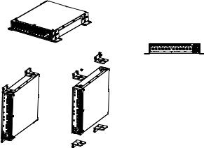
Figure 1-1. Bracket Installation for Rack Mounting
2Insert the supplied screws into the rack mounting holes and tighten with a screwdriver.
3Repeat the process for the rack-mounting bracket on the other side of the switch.
4Insert the switch into the rack, making sure the rack-mounting holes on the switch line up to the mounting holes on the rack.
5Secure the switch to the rack with the rack screws (not provided). Fasten the lower pair of screws before the upper pair of screws. Make sure that the ventilation holes are not obstructed.
Flat Surface Installation
The switch can be installed on a flat surface if it is not installed on a rack. The surface must be able to support the weight of the switch and the switch cables.
1Attach the self-adhesive rubber pads (provided with the switch) on each marked location on the bottom of the chassis.
2Set the switch on a flat surface, while leaving two inches (5.08 cm) on each side and five inches (12.7 cm) at the back.
3Make sure that the switch has proper ventilation.
Getting Started Guide |
|
5 |
|
Wall Installation
To mount the switch on a wall:
1Make sure that the mounting location meets the following requirements:
•The surface of the wall must be capable of supporting the switch.
•Allow at least two inches (5.1 cm) space on the sides for proper ventilation and five inches (12.7 cm) at the back for power cable clearance.
•The location must be ventilated to prevent heat buildup.
2Place the supplied wall-mounting bracket on one side of the switch, verifying that the mounting holes on the switch line up to the mounting holes on the wall-mounting bracket.
Figure 1-2. Bracket Installation for Wall Mounting
3Insert the supplied screws into the wall-mounting bracket holes and tighten with a screwdriver.
4Repeat the process for the wall-mounting bracket on the other side of the switch.
5Place the switch on the wall in the location where the switch is being installed.
6On the wall mark the locations where the screws to hold the switch must be prepared.
6 |
|
Getting Started Guide |
|

7On the marked locations, drill the holes and place all plugs (not provided) in the holes.
8Secure the switch to the wall with screws (not provided). Make sure that the ventilation holes are not obstructed.
Starting and Configuring the Switch
Management Modes
The Dell Networking X1008/18/26 and equivalent PoE versions have a Mode push button that toggles between Managed and Unmanaged Modes. The MGMT LED is on when the switch is in Managed Mode and is off when in Unmanaged Mode. To configure the switch while in Managed Mode, see the following sections.
NOTE: Release notes and user documentation can be downloaded from dell.com/support.
Connecting the Switch to the Network
CAUTION: Do not plug a phone jack connector into an RJ-45 port. This will damage the Ethernet switch. Use only twisted-pair cables with RJ-45 connectors that conform to FCC standards.
To connect the switch to the network:
•Attach one end of a twisted-pair cable to the switch's RJ-45 connector and the other end of a twisted-pair cable to another switch or server.
As each connection is made, the link LED corresponding to each port on the switch is illuminated (green or amber) indicating that the connection is valid.
Getting Started Guide |
|
7 |
|

Initial Configuration Through the Web
The administrator can perform switch configuration using the web management GUI.
To configure the switch, perform the following:
1Verify that the switch is in Managed Mode.
2Connect the switch to a PC using Ethernet, and set a static IP address of 192.168.2.x (where x is between 2 and 254) and subnet mask of 255.255.255.0 on the PC. Note that the switch acts as a DHCP client and can receive its IP address from a DHCP server. If using DHCP for IP assignment, look up the assigned IP address and use it for the next step.
3Connect to the switch using the default switch IP address 192.168.2.1 in your web browser. The login username is admin with password admin.
4After logging into the switch using the previous step, a getting started wizard is available to guide the user through the initial switch configuration. Applied changes are automatically saved to the startup configuration.
CLI Access
To access the switch using the Command Line Interface (CLI), it must be in Managed Mode. The Command Line Interface can only be reached by using telnet or a console connection. See the user guide for limited CLI options.
NOTE: The default switch setting is Unmanaged Mode. To set the switch to Managed Mode, press the Mode button for at least seven seconds.
Connecting the Switch to a Terminal Server/PC
NOTE: The console port enables connecting to a terminal or desktop system running terminal emulation software for monitoring or debugging the device using the micro-USB port. (You can find the USB drivers at dell.com/support.)
To use the console port, the following is required (e.g., PuTTY, TeraTerm, etc.)
•VT100 compatible terminal or a desktop or portable system with a USB port and running VT100 terminal emulation software.
8 |
|
Getting Started Guide |
|
To connect a terminal to the device console port, verify that the terminal emulation software is set as follows:
1Set the data rate to 9600 baud, data format to 8 data bits, 1 stop bit and no parity.
2Set flow control to none.
3Select VT100 for Emulation mode.
Rebooting the Switch in Managed Mode
To reboot the switch, press the Reset button through the pinhole on the switch for less than seven seconds.
Resetting the Switch in Managed Mode
To reset the switch to factory defaults, press the Reset button through the pinhole on the switch for more than seven seconds.
CAUTION: When you reset the switch, any configuration information that has been previously entered is lost.
Power Over Ethernet
The table below describes the PoE resources available for the various switch models.
Table 1-2. Power Over Ethernet
PoE Switch Model |
Watts (dedicated POE |
Powered Ports |
|
power only) |
|
|
|
|
X1008 |
123 |
1-8 |
|
|
|
X1018p |
246 |
1-16 |
|
|
|
X1026p |
369 |
1-24* |
|
|
|
X1052p |
369 |
1-24* |
|
|
|
*These ports can be PoE or PoE+
Getting Started Guide |
|
9 |
|
10 |
|
Getting Started Guide |
|

Dell™ Networking™ X1000 X4000
X1008 X1008P X1018 X1026 X4012 X1018P X1026P X1052 X1052P
 “ ”
“ ”
 “ ”
“ ”
 “ ”
“ ”
____________________
© 2014 Dell Inc.
Dell™ Dell Dell Inc. /
P/N RF9YW Rev. A00

Dell X
X1008/X1008P X1018/X1018P X1026/X1026P X1052/X1052P X4012
Unmanaged ModeUnmanaged Mode Mode
7 Managed Mode MGMT LED
Unmanaged Mode
Dell
dell.com/support(SERI)
•AC X1008 X1008P
•micro-USB
13

X1000 X4000
1-1. X1000 X4000
|
|
|
|
|
|
|
|
X1008 |
24W |
E08W |
E08W001 |
X1008P |
150W |
E09W |
E09W001 |
X1018 |
40W |
E10W |
E10W001 |
X1026 |
40W |
E10W |
E10W002 |
X4012 |
100W |
E10W |
E10W003 |
X1018P |
280W |
E11W |
E11W001 |
X1026P |
450W |
E11W |
E11W002 |
X1052 |
100W |
E12W |
E12W001 |
X1052P |
525W |
E12W |
E12W002 |
|
|
|
|
 SERI
SERI


52
1 架安装托座上的安装孔对齐。
14

1-1.
5 然后再拧紧上方的螺钉对。确保通风孔畅通无阻。
撑交换机和交换机电缆的重量。
22 5.085 12.7
15

•2 5.15 12.7
2 墙壁式安装托座上的安装孔对齐。
1-2.
16

Dell X1008/18/26 PoE Mode Managed Mode Unmanaged ModeMGMT LED Managed ModeManaged Mode
dell.com/support
 RJ-45FCC RJ-45
•RJ-45
LED
GUI
1Managed Mode
2PC PC IP 192.168.2.xx 2 254 255.255.255.0DHCP DHCP IP DHCP IP IP
3IP 192.168.2.1admin admin
4 配置。应用的更改会自动保存到启动配置。
17
Loading...