


 Loading...
EN
TECHNICAL MANUAL
Mini Hands-free door entry monitor |
|
Art. 6741W - Art. 6741W/BM |
Passion.Technology.Design. |
|

Table of contents |
|
Warning |
|
Description....................................................................................... |
3 |
Technical characteristics................................................................ |
4 |
Installation........................................................................................ |
5 |
Removing the monitor.............................................................................. |
6 |
Removing/Fitting the terminal................................................................. |
6 |
Connections..................................................................................... |
7 |
Operation.......................................................................................... |
7 |
Answering an incoming call..................................................................... |
7 |
Activation/deactivation of Hands-free function..................................... |
7 |
Touch buttons................................................................................... |
8 |
Description................................................................................................ |
8 |
Indicator LED............................................................................................ |
8 |
Configuration.................................................................................... |
9 |
Building mode, Kit mode.......................................................................... |
9 |
Power management................................................................................. |
9 |
N.B.............................................................................................................. |
9 |
Addressing table............................................................................ |
10 |
Programmable buttons.................................................................. |
11 |
Legend.............................................................................................. |
11 |
Basic configuration................................................................................. |
11 |
Advanced configuration......................................................................... |
12 |
Intercom calls: introduction............................................................... |
12 |
Selective intercom address: programming/cancellation............ |
12 |
Button programming.................................................................. |
13 |
Direct programming .................................................................. |
14 |
Generic actuator, Addressable actuator: button programming......... |
15 |
Remote camera module: button programming................................. |
16 |
Other functions.................................................................................. |
17 |
Programming range................................................................................ |
18 |
Changing monitor ringtones.................................................................. |
18 |
Programming reset................................................................................. |
19 |
Compatible secondary monitors.................................................. |
20 |
Art. 6741W (/BM) in systems powered by 4888C (/CU)............... |
20 |
Installation rules...................................................................................... |
20 |
New coding from rev. 053...................................................................... |
20 |
Operating distances............................................................................... |
21 |
Art. 6741W (/BM) in systems powered by 1210........................... |
22 |
Operating distances............................................................................... |
22 |
Art. 6741W (/BM) in kit systems 8451V......................................... |
23 |
Operating distances............................................................................... |
23 |
Wiring diagrams............................................................................. |
24 |
System powered by art. 4888C / 4888CU............................................. |
24 |
System powered by art. 1210................................................................ |
25 |
Kit 8451V: basic single-family system powered by art. 1209.............. |
25 |
Art. 6741W (/BM) and a secondary monitor in branch connection.... |
26 |
Art. 6741W (/BM) and a 6721W (/BM) secondary monitor in cascade |
|
connection............................................................................................... |
26 |
System performance and layouts................................................. |
27 |
2

Description
Monitors 6741W and 6741W/BM are hands-free colour video internal units, for installation in 2-wire video entry phone systems and compatible only with power supply units 1209, 1210, 4888C and 4888CU.
The monitor, used in conjunction with the COMELIT app, makes it possible to answer calls directly from your smartphone/ tablet, whether you are at home or away.
The 6741W/BM monitor includes a magnetic induction amplification system as standard. Backplate art. 6710 is not supplied, and is available to purchase separately.
1 |
2 |
4 |
3
5
6
7 |
8 |
9 |
10 |
11 |
12 |
13 |
1.Brightness control
ff To increase the value, turn clockwise
2.Loudspeaker volume control
ff To increase the value, turn clockwise
3.Call volume adjustment (high - medium - low)
4.4.3” LCD colour screen
5.Speaker and audio activation button
6.Touch-sensitive buttons
7.S1  Microswitches for setting the user code (see “Addressing table”)
8.S2  Microswitches for programming buttons and functions DIP 1-2-3-4 for button function programming
DIP 5-6 access to programming
DIP 7 for power supply voltage management (Paragraph “Power management”) default = OFF
DIP 8 (not used)
9.10. Factory setting - DO NOT CHANGE!
11.CV 5 Jumper for video closure
12.Pin for securing terminal block
13.S3 Microswitches:
DIP 1 to set the correct operating mode (Paragraph “Building mode, Kit mode”)
DIP 2 (not used)
Terminal block for system connection:
LL BUS line connection terminals
CFP1 CFP2 Outside door call input
3

Technical characteristics
MAIN FEATURES |
6741W |
6741W/BM |
Building Kit audio/video system |
Yes |
Yes |
SimpleBus Top audio/video system |
Yes |
Yes |
Audio/Video Kit |
Yes |
Yes |
Surface-mounted |
Yes |
Yes |
Backplate supplied |
Yes |
No |
Desk base-mounted |
Yes |
Yes |
Hands-free |
Yes |
Yes |
Induction loop |
No |
Yes |
Display |
LCD |
LCD |
Display size (inches) |
4.3'' 16:9 |
4.3'' 16:9 |
OSD display |
Yes |
Yes |
Display resolution (H x V) |
480 x 272 pixel |
480 x 272 pixel |
B/W or colour display |
Colour |
Colour |
Product colour |
White |
White |
Sensitive Touch technology |
Yes |
Yes |
Number of buttons as standard |
8 |
8 |
LED indication (n) |
4 |
4 |
Backlighting colour |
White |
White |
Wi-Fi |
Yes |
Yes |
Compatible with Comelit app |
Yes |
Yes |
HARDWARE CHARACTERISTICS |
|
|
Removable terminals |
Yes |
Yes |
ADJUSTMENTS |
|
|
Loudspeaker volume |
Yes |
Yes |
Brightness |
Yes |
Yes |
GENERAL DATA |
|
|
Product height (mm) |
160 |
160 |
Product width (mm) |
115 |
115 |
Product depth (mm) |
22 |
22 |
TECHNICAL CHARACTERISTICS |
|
|
Power supply voltage |
22-34 Vdc |
22-34 Vdc |
Absorption in standby (mA) |
3–3,5 (Building mode) |
3–3,5 (Building mode) |
|
45-70 (Kit mode) |
45-70 (Kit mode) |
Absorption during call (mA) |
150-180 |
150-180 |
Absorption during communication (mA) |
250-300 |
250-300 |
IP rating |
30 |
30 |
Operating temperature (°C) |
+ 5/+40 |
+ 5/+40 |
Video encoding |
PAL/NTSC |
PAL/NTSC |
Terminals |
L L CFP1 CFP2 |
L L CFP1 CFP2 |
Network connection |
WLan |
WLan |
Video resolution (H x V) |
480 x 272 |
480 x 272 |
4

Installation
Before definitive installation of the monitors, make sure the device has good Wi-Fi signal reception; the distance between the router and monitors, and the construction materials used in the walls are factors that can affect signal quality.
The Wi-Fi signal is not strong enough to guarantee correct operation. A Wi-Fi repeater must be installed between the router and monitor in order to boost the Wi-Fi signal received by the monitor.
115 mm
mm 160
Optional |
fixing |
1A |
2 |
1B |
3 |
1C |
4 |
5 |
|
|
1 |
5 |
2 |
6 |
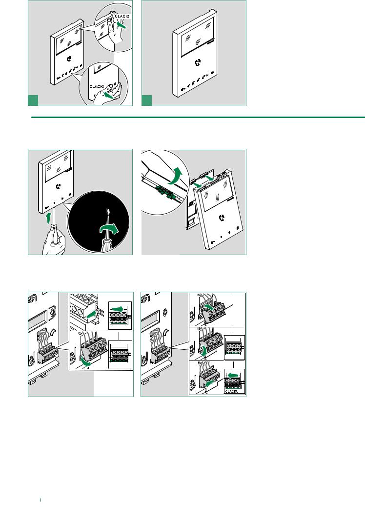
Removing the monitor
4 |
1 |
2 |
Removing/Fitting the terminal
1 |
|
|
2 |
|
|
1 |
|
|
2 |
|
|
3 |
|
|
|
|
P2 |
|
P1 |
CF |
|
|
|
L |
CF |
|
L |
|
|
3 |
|
|
6
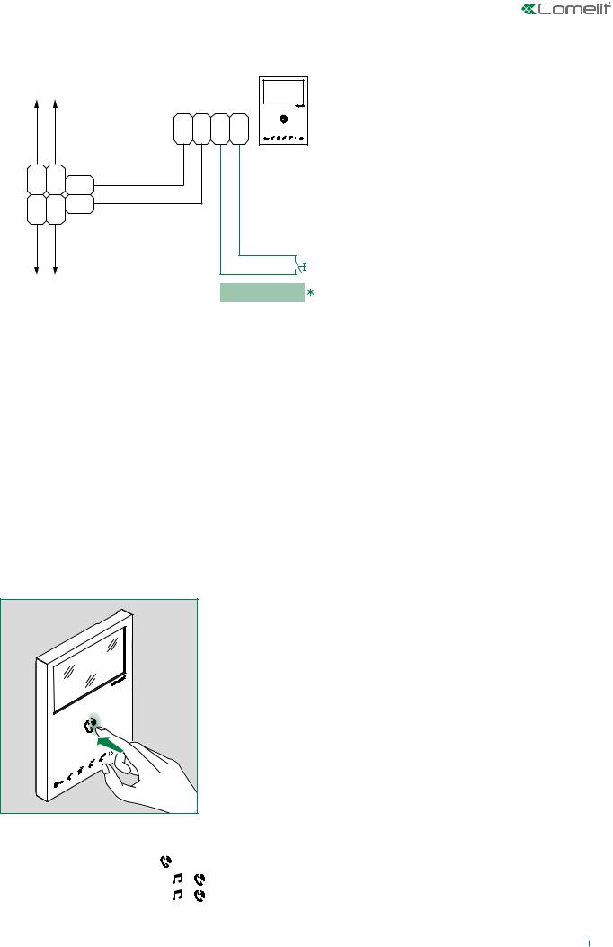
Connections
VIDEO ENTRY
SYSTEM RISER
|
|
L L |
C |
C |
|
|
F1 |
F2 |
|
|
|
P |
P |
|
L |
L |
1214/2C |
|
6741W |
LM |
|
6741W/BM |
||
OUT OUT |
|
|
||
L |
L |
LM |
|
|
IN IN |
|
|
|
|
VIDEO ENTRY SYSTEM RISER
FROM FLOOR DOOR CALL
 20 m MAX - Use shielded cable for the connection and do not route the cables in the vicinity of heavy inductive loads or power supply cables (230V/400V).
Where multiple door-entry phones or monitor backplates have the same user code, connect the CFP button on one only; all the devices will ring simultaneously.
Operation
Once connected to the power supply, the LEDs for monitor 6741W (/BM) will flash: wait for them to turn off (approx. 40 seconds) before starting to use the device.
Answering an incoming call
Press the touch-sensitive audio activation button  to answer the incoming call.
Activation/deactivation of Hands-free function
ff Long press (5 sec) the button |
|
|
|
»» |
ACTIVATION: |
+ |
LED STEADY ON |
»» |
DEACTIVATION: |
+ |
LED OFF |
7

Touch buttons
Description
ff Press the desired button once to activate the function associated with it.
Wait for approx. 1 sec. before pressing the same button again; rapidly pressing the same button repeatedly will cancel the command which has just been sent.
Audio activation |
|
Door opener control |
[programmable] |
Actuator |
[programmable] |
** Self-ignition |
[programmable] |
Secondary Switchboard |
[programmable] |
** Doctor mode Automatic door opening on receipt of call from external unit. |
[programmable] |
Menu |
[not programmable] |
Privacy mode. The ringtone will be silenced on receipt of a call from the |
[not programmable] |
external unit and from the switchboard.. |
|
Arrow keys |
|
Confirm selection |
|
Message menu |
|
** Long press on key to enable / disable the function. |
|
Indicator LED
Audio
Lock-release
Privacy mode
Menu
FLASHING LED |
Incoming call |
STEADY LED in call |
In communication |
STEADY LED in standby |
Hands-free function enabled |
FLASHING LED |
Incoming call |
FLASHING LED (slow) |
Door open indication |
1 FLASH |
Door opening confirmation |
STEADY LED |
Privacy mode active |
STEADY AND FLASHING LED (3 every 5 sec) |
Doctor and Privacy mode active |
OFF AND FLASHING LED (3 every 5 sec) |
Doctor mode active |
4 FLASHES |
The called device is busy |
FLASHING LED |
User notification present |
8
Configuration
Building mode, Kit mode
For correct configuration, set DIP 1 of S3 (on/off) as follows:
•BUILDING Mode: (S3) DIP 1= OFF
√√ BUILDING mode must be set in systems powered by 4888C / 4888CU, while for systems powered by 1210, set BUILDING mode when the number of 6741W (/BM) monitors is greater than 10.
In this mode you can answer video entry phone calls at home and away from your smartphone/tablet.
•Kit Mode: (S3) DIP 1= ON
√√ KIT mode is permitted in systems powered by 1210 with 10 or fewer internal units, and in systems powered by 1209 with 4 or fewer 6741W (/BM) units.
In this mode you can answer video entry phone calls at home and away from your smartphone/tablet, but also implement selfignition and control actuators.
QTY |
|
art. 4888C / 4888CU |
art. 1210 |
art. 1209 |
|||||||||||||||||||
|
|
|
|
|
|
|
|
|
|
|
|
|
|
|
|
|
|
|
|
|
|
|
|
art. 6741W (/BM) |
< 10 |
S3 |
|
|
|
|
|
OFF |
S3 |
|
|
|
|
ON |
S3 |
|
|
|
|
|
|
|
ON (art. 6741W (/BM) MAX 4) |
|
|
|
|
|
|
|
|
|
|
|
|
|
|
|
|
||||||||
|
|
|
|
|
|
|
|
|
|
|
|
|
|
|
|
||||||||
|
|
|
|
|
|
|
|
|
|
|
|
|
|
|
|
|
|
|
|
|
|||
|
|
|
|
|
|
|
|
|
|
|
|
|
|
|
|
|
|
|
|
|
|
|
|
art. 6741W (/BM) |
> 10 |
S3 |
|
|
|
|
OFF |
S3 |
|
|
|
|
OFF |
- |
|
|
|
|
|
|
|
|
|
|
|
|
|
|
|
|
|
|
|
|
|
|
|
|
|
||||||||
|
|
|
|
|
|
|
|
|
|
|
|
|
|
|
|
||||||||
|
|
|
|
|
|
|
|
|
|
|
|
|
|
|
|
||||||||
|
|
|
|
|
|
|
|
|
|
|
|
|
|
|
|
|
|
|
|
|
|||
|
|
|
|
|
|
|
|
|
|
|
|
|
|
|
|
|
|
|
|
||||
|
|
|
|
|
|
|
|
|
|
|
|
|
|
|
|
|
|
|
|
|
|
|
|
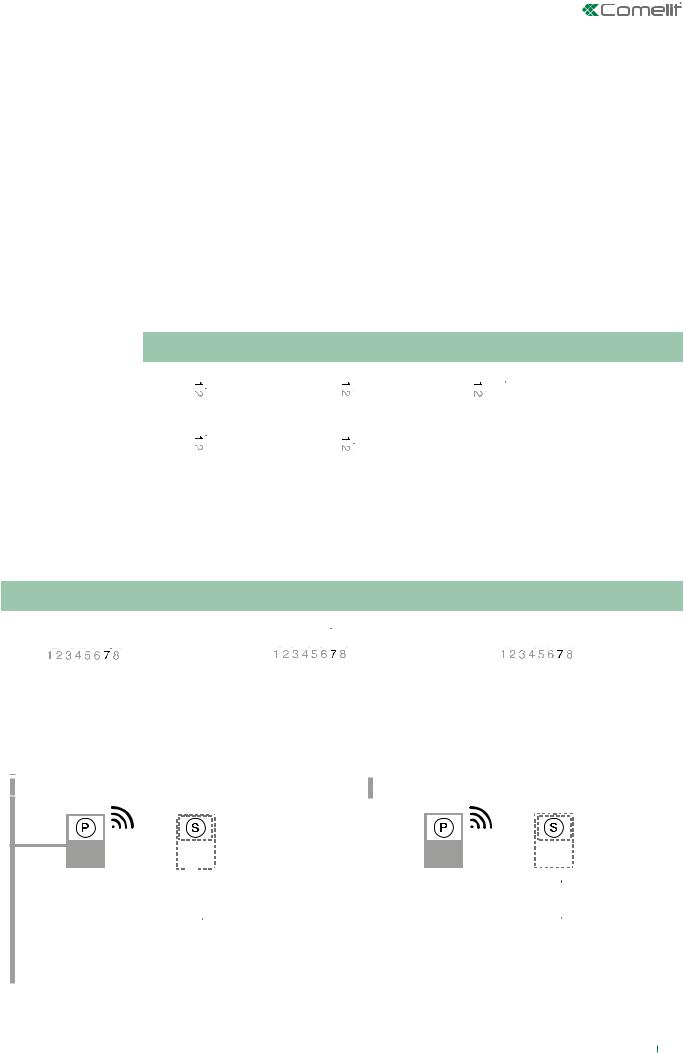
Power management
For correct power supply management, main monitor  and secondary monitor
  DIP 7 of S2 should be set in accordance with the table (see below) and in accordance with the type of system and its configuration:
art. 4888C / 4888CU |
|
art. 1210 |
|
art. 1209 |
|
||||||||||||||||||||||||||||||||||||||||||||||
|
|
|
|
|
|
|
|
|
|
|
|
|
|
|
|
|
|
|
|
|
|
|
|
|
|
|
|
|
|
|
|
|
|
|
|
|
|
|
|
|
|
|
|
|
|
|
|
|
|
|
|
S2 |
|
|
|
|
|
|
|
|
|
|
|
|
|
|
|
|
OFF |
S2 |
|
|
|
|
|
|
|
|
|
|
|
|
|
|
|
ON |
S2 |
|
|
|
|
|
|
|
|
|
|
|
|
|
|
|
ON |
|
|
|
|
|
|
|
|
|
|
|
|
|
|
|
|
|
|
|
|
|
|
|
|
|
|
|
|
|
|
|
|
|
|
|
|
|
|
|
|
|
|
|
|
|
|
||||||
|
|
|
|
|
|
|
|
|
|
|
|
|
|
|
|
|
|
|
|
|
|
|
|
|
|
|
|
|
|
|
|
|
|
|
|
|
|
|
|
|
|
|
|
|
|
|
|
|
|||
|
|
|
|
|
|
|
|
|
|
|
|
|
|
|
|
|
|
|
|
|
|
|
|
|
|
|
|
|
|
|
|
|
|
|
|
|
|
|
|
|
|
|
|
|
|
|
|
|
|
|
|
|
|
|
|
|
|
|
|
|
|
|
|
|
|
|
|
|
|
|
|
|
|
|
|
|
|
|
|
|
|
|
|
|
|
|
|
|
|
|
|
|
|
|
|
|
|
|
|
|
|
|
|
|
|
|
|
|
|
|
|
|
|
|
|
|
|
|
|
|
|
|
|
|
|
|
|
|
|
|
|
|
|
|
|
|
|
|
|
|
|
|
|
|
|
|
|
|
|
|
|
|
|
|
|
|
|
|
|
|
|
|
|
|
|
|
|
|
|
|
|
|
|
|
|
|
|
|
|
|
|
|
|
|
|
|
|
|
|
|
|
|
|
|
|
|
|
|
|
|
|
|
|
|
|
|
|
N.B.
A single 6741W monitor can be installed for each user code; this will also be the only main monitor.
6741W |
|
6741W |
6741W/BM |
|
6741W/BM |
|
|
|
|
|
|
|
|
|
|
|
|
|
|
|
|
|
|
|
|
|
|
|
|
|
|
|
|
|
|
|
|
|
|
|
|
|
|
|
|
|
|
DIP 7 |
|
|
|
DIP 7 |
|
|
|
|
DIP 7 |
|
ON |
DIP 7 |
|
ON |
||||||
(S2) |
|
OFF |
(S2) |
|
OFF |
|
|
(S2) |
|
|
(S2) |
|
|
|||||||
|
|
|
|
|
|
|
|
|
|
|
|
|
|
|
|
|
|
|
|
|
|
|
|
|
|
|
|
|
|
|
|
|
|
|
|
|
|
|
|
|
|
|
|
|
|
|
DIP 8 |
|
ON |
|
|
|
|
|
|
|
DIP 8 |
|
ON |
|||
|
|
|
|
|
|
|
|
|
|
|
|
|
|
|||||||
|
|
|
|
|
(S2) |
|
|
|
|
|
|
|
|
|
(S2) |
|
|
|||
|
|
|
|
|
|
|
|
|
|
|
|
|
|
|
|
|
|
|
|
|
|
|
|
|
|
|
|
|
|
|
|
|
|
|
|
|
|
|
|
|
|
4888C / 4888CU |
1210 / 1209 |
9
Loading...