


IT |
EN |
FR |
NL |
DE |
ES |
PT |
MANUALE |
TECHNICAL |
MANUEL |
TECHNISCHE |
TECHNISCHES |
MANUAL |
MANUAL |
TECNICO |
MANUAL |
TECHNIQUE |
HANDLEIDING |
HANDBUCH |
TÉCNICO |
TÉCNICO |
Art.1409
Manuale tecnico accessorio Art. 1409 |
|
|
Technical manual for accessory Art. 1409 |
|
|
Manuel technique accessoire Art. 1409 |
|
|
Technische handleiding accessoire Art. 1409 |
Passion.Technology. Design. |
|
Technisches Handbuch Zubehör Art. 1409 |
||
|
||
Manual técnico del accesorio Art. 1409 |
|
|
Manual técnico acessório Art. 1409 |
|
|
|
|

IT
Avvertenze
•Effettuare l’installazione seguendo scrupolosamente le istruzioni fornite dal costruttore ed in conformità alle norme vigenti.
•Tutti gli apparecchi devono essere destinati esclusivamente all’uso per cui sono stati concepiti. Comelit Group S.p.A. declina ogni responsabilità per un utilizzo improprio degli apparecchi, per modifiche effettuate da altri a qualunque titolo e scopo, per l’uso di accessori e materiali non originali.
•Tutti i prodotti sono conformi alle prescrizioni delle direttive 2014/30/UE, 2014/35/UE e ciò è attestato dalla presenza della marcatura CE sugli stessi.
•Evitare di porre i fili di montante in prossimità di cavi di alimentazione (230/400V).
•Gli interventi di installazione, montaggio e assistenza agli apparecchi elettrici devono essere eseguiti esclusivamente da elettricisti specializzati.
•Togliere l’alimentazione prima di effettuare qualsiasi manutenzione.
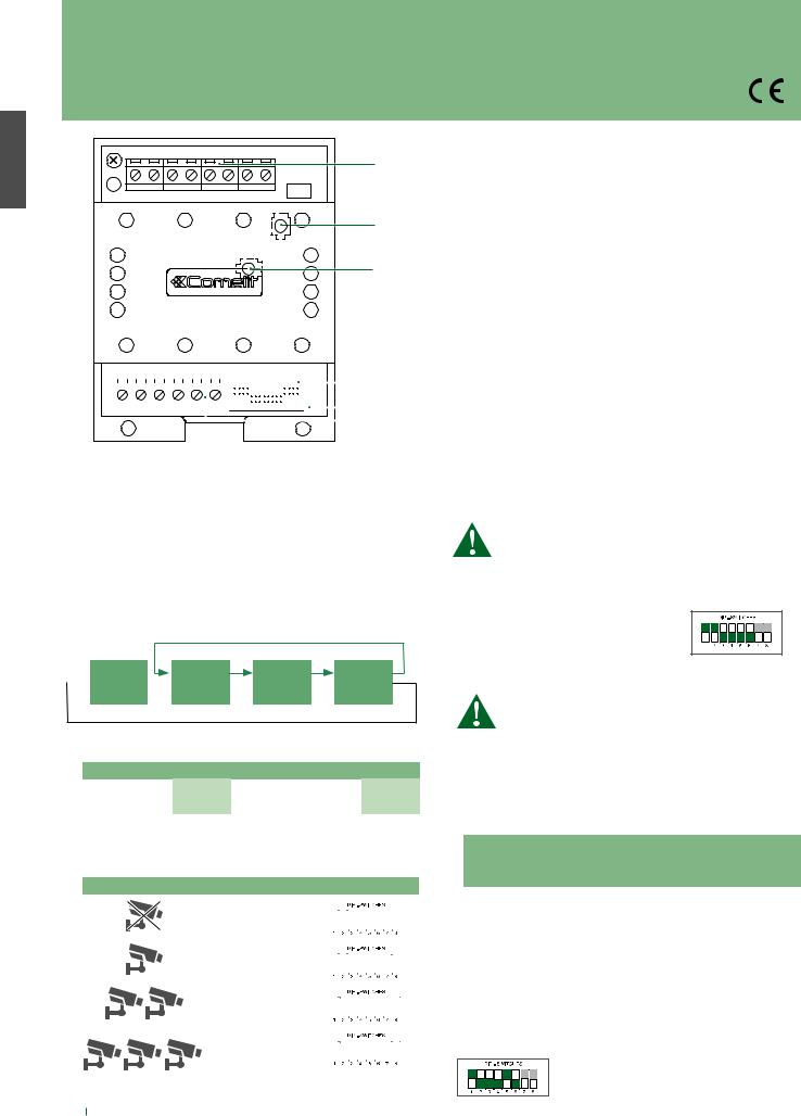
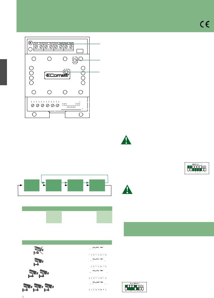
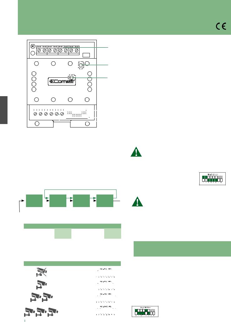
1.Morsettiera M2 per connessione impianto:
1.INA Contatto comando esterno modulo telecameraContatto comune
|
|
GND |
|
|
V1 S1 Ingresso coassiale telecamera 1 |
|
|
V2 S2 Ingresso coassiale telecamera 2 |
2. |
|
V3 S3 Ingresso coassiale telecamera 3 |
2. |
TRIMMER TM2 Regolazione frequenza modulazione segnale video |
|
|
|
(regolato in modo ottimale in fabbrica, non variare). |
|
3. |
TRIMMER TM1 Regolazione ampiezza segnale video modulato |
3. |
|
(regolato in modo ottimale in fabbrica, non variare). |
|
4. |
Microinterruttori S1 di programmazione. |
|
5. |
LED di segnalazione DL1 |
|
|
spento: nessun video proveniente dalle telecamere 1, 2 o 3 |
|
|
acceso: il video trasmesso sul monitor proviene dalla telecamera |
|
|
1, 2 o 3. |
|
6. |
Morsettiera M1 per connessione impianto: |
|
|
L OUT L OUT Uscita linea Bus |
|
|
|
|
|
|
|
|
|
|
|
|
|
|
|
|
|
|
|
|
|
|
|
|
|
|
|
|
|
4. |
L IN L IN Ingresso linea Bus |
||
|
|
|
|
|
|
|
|
|
|
|
|
|
|
|
|
|
|
|
|
|
|
|
|
|
|
|
|
|
|
|
5. |
~- ~+ Ingresso alimentazione 12Vac 20Vdc. |
|
|
|
|
|
|
|
|
|
|
|
|
|
|
|
|
|
|
|
|
|
|
|
|
|
|
|
|
|
|
|
||
|
|
|
|
|
|
|
|
|
|
|
|
|
|
|
|
|
|
|
|
|
|
|
|
|
|
|
|
|
|
|
||
|
|
|
|
|
|
|
|
|
|
|
|
|
|
|
|
|
|
|
|
|
|
|
|
|
|
|
|
|
|
|
|
|
|
|
|
|
|
|
|
|
|
|
|
|
|
|
|
|
|
|
|
|
|
|
|
|
|
|
|
|
|
|
6. |
|
|
|
|
|
|
|
|
|
|
|
|
|
|
|
|
|
|
|
|
|
|
|
|
|
|
|
|
|
|
|
|
|
||
Funzionamento e programmazione
L'Art. 1409 permette di gestire telecamere analogiche CCTV (fino a 3).
L'Art. 1409 è utilizzabile in impianti con Art. 1210 o 1209 e in impianti con Art. 4888C nella tratta SB2 (dall'alimentatore miscelatore verso i videocitofoni/citofoni).
√√ Con monitor acceso
Premere il bottone programmato, per ciclare tutte le telecamere collegate, secondo il seguente schema. Il ciclico è azionabile utilizzando anche un contatto pulito (C-NO) collegandolo all’ingresso INA – GND (vedi schema: SB2V/023ASMC)
MODALITÁ CON PORTER AUDIO O CENTRALINO
Posto |
1° |
2° |
3° |
|||
esterno |
|
Telecamera |
|
Telecamera |
|
Telecamera |
MODALITÁ ATTUATORE GENERICO O INDIRIZZATO
CONFIGURAZIONE DI DEFAULT
MODALITÀ |
DIP 1 |
DIP 2 |
DIP 3 |
DIP 4 |
DIP 5 |
DIP 6 |
DIP 7 |
DIP 8 |
|
|
|
|
|
|
|
|
|
Porter video |
|
|
|
|
|
|
|
|
Attuatore generico |
ON |
ON |
OFF |
OFF |
OFF |
OFF |
ON |
ON |
3 telecamere |
|
|
|
|
|
|
|
|
|
|
|
|
|
|
|
|
|
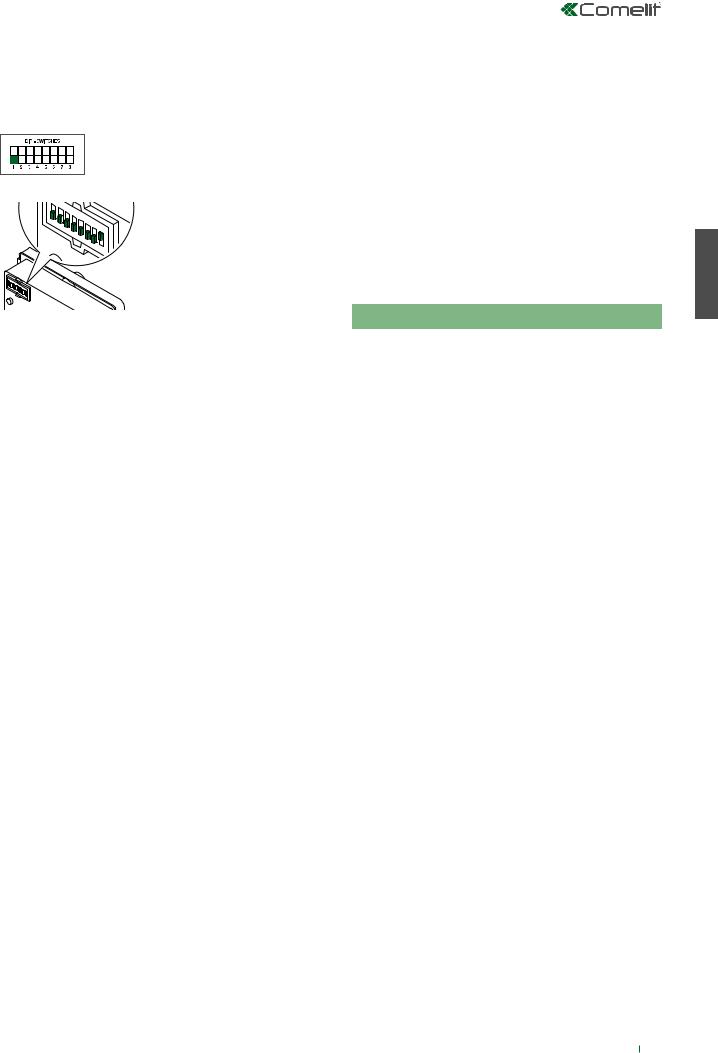
PROGRAMMAZIONE NUMERO TELECAMERE CONNESSE
Impostare il numero di telecamere connesse usando i dip switch 7 e 8, come mostrato nella seguente tabella:
|
DIP 7 |
DIP 8 |
|
||||||||||
|
0 |
0 |
|
|
|
|
|
|
|
|
|
|
|
|
|
|
|
|
|
|
|
|
|
||||
|
|
|
|
|
|
|
|
|
|
|
|
|
|
|
|
|
|
|
|
|
|
|
|
|
|
|
|
|
1 |
0 |
|
|
|
|
|
|
|
|
|
|
|
|
|
|
|
|
|
|
|
|
|
||||
|
|
|
|
|
|
|
|
|
|
|
|
|
|
|
|
|
|
|
|
|
|
|
|
|
|
|
|
|
0 |
1 |
|
|
|
|
|
|
|
|
|
|
|
|
|
|
|
|
|
|
|
|
|
||||
|
|
|
|
|
|
|
|
|
|
|
|
|
|
|
|
|
|
|
|
|
|
|
|
|
|
|
|
|
1 |
1 |
|
|
|
|
|
|
|
|
|
|
|
|
|
|
|
|
|
|
|
|
|
|
|
||
|
|
|
|
|
|
|
|
|
|
|
|
|
|
|
|
|
|
|
|
|
|
|
|
|
|
|
|
1. MODALITÀ ATTUATORE GENERICO
Prima di procedere con la programmazione del modulo, vedi "5. Tabella di compatibilità Art.1409".
In questa modalità, sul videocitofono con monitor acceso, sarà possibile ciclare tutte le telecamere collegate premendo ripetutamente il pulsante programmato come "attuatore generico".
È necessario impostare il micro interruttore “S1” come mostrato di seguito.
2. MODALITÀ ATTUATORE INDIRIZZATO
Prima di procedere con la programmazione del modulo, vedi "5. Tabella di compatibilità Art.1409".
In questa modalità, sul videocitofono con monitor acceso, premendo ripetutamente il pulsante programmato come "attuatore indirizzato", sarà possibile ciclare SOLO le telecamere collegate all'Art. 1409 con indirizzo corrispondente.
Per attivare la funzione, programmare il pulsante sul monitor come attuatore indirizzato (con indirizzo compreso tra 220 e 227) e impostare il selettore “S1” come mostrato nella seguente tabella:
|
|
S1 |
|
|
Corrispondenza indirizzo 1409 |
|||
|
|
|
|
attuatore indirizzato |
||||
|
|
|
|
|
|
|||
DIP 1 |
DIP 2 |
DIP 3 |
DIP 4 |
DIP 5 |
DIP 6 |
Indirizzo |
Codice attuattore |
|
1409 |
su monitor |
|||||||
|
|
|
|
|
|
|||
1 |
0 |
0 |
0 |
0 |
0 |
0 |
220 |
|
1 |
0 |
1 |
0 |
0 |
0 |
1 |
221 |
|
1 |
0 |
0 |
1 |
0 |
0 |
2 |
222 |
|
1 |
0 |
1 |
1 |
0 |
0 |
3 |
223 |
|
|
|
|
|
|
|
|
|
|
1 |
0 |
0 |
0 |
1 |
0 |
4 |
224 |
|
|
|
|
|
|
|
|
|
|
1 |
0 |
1 |
0 |
1 |
0 |
5 |
225 |
|
|
|
|
|
|
|
|
|
|
1 |
0 |
0 |
1 |
1 |
0 |
6 |
226 |
|
|
|
|
|
|
|
|
|
|
1 |
0 |
1 |
1 |
1 |
0 |
7 |
227 |
|
|
|
|
|
|
|
|
|
|
Sul medesimo impianto è possibile installare fino ad 8 moduli Art. 1409 con 8 codici distinti.
Esempio impostazione indirizzo su Art. 1409 per comando tramite codice attuatore 224
2

3. MODALITÀ CON POSTO ESTERNO AUDIO
Le modalità attuatore generico/indirizzato possono essere utilizzate anche su un impianto che prevede un posto esterno solo audio Art. 1622 - 1621.
Per il funzionamento con posto esterno "solo audio":
1.impostare il DIP 1 del selettore “S1” come mostrato di seguito:
2.impostare il posto esterno in modalità video come nell'immagine seguente:
|
76 |
|
|
|
5 |
|
|
4 |
IP |
|
3 |
|
2 |
|
D |
1 |
|
|
|
|
|
|
N |
|
|
O |
In questa modalità ad ogni chiamata dal posto esterno o autoaccensione il monitor si accende e visualizza l’immagine della prima telecamera connessa all’Art. 1409. Sarà possibile ciclare tutte le telecamere collegate premendo ripetutamente il pulsante programmato.
4. MODALITÀ CON CENTRALINO 1998A
Le modalità attuatore generico/indirizzato possono essere utilizzate anche su un impianto che prevede Chiamata Video da centralino. In questa modalità, ad ogni chiamata video proveniente dal centralino, il monitor si accenderà non appena si solleva la cornetta (o si preme il tasto presa fonica) e l’immagine visualizzata sarà quella proveniente dalla prima telecamera connessa all’Art. 1409.
A questo punto ad ogni pressione del pulsante di comando (vedi modalità attuatore generico/indirizzato) o ad ogni chiusura del contatto manuale (disponibile collegando il contatto INA-GND ai morsetti OUT-OUT del centralino come nello schema IK/EN/004QC), sarà possibile ciclare tutte le telecamere disponibili.
Per utilizzare questa funzione è necessario collegare il modulo telecamere scorporate necessariamente sulla linea Bus in uscita dai morsetti LM-LM del centralino e impostare il centralino in "modalità Video" prima della chiamata.
5. TABELLA DI COMPATIBILITÀ ART. 1409 CON 1256 O ALTRI 1409
|
Modalità attuatore |
Modalità attuatore |
|
|
generico |
indirizzato |
|
Compatibilità |
No 1256 |
No 1256 in modalità |
|
in modalità attuatore |
attuatore indirizzato con |
||
con 1256 |
|||
generico |
codici tra 220 e 227 |
||
|
|||
Compatibilità |
Nessun altro 1409 in |
Solo 1409 in modalità 2 |
|
modalità attuatore |
|||
con Art. 1409 |
con 8 codici distinti |
||
generico |
|||
|
|
IT
3
EN
Warning
•Install the equipment by carefully following the instructions given by the manufacturer and in compliance with the standards in force.
•All the equipment must only be used for the purpose it was designed for. Comelit Group S.p.A. declines any responsibility for improper use of the apparatus, for any alterations made by others for any reason or for the use of non-original accessories or materials.
•All the products comply with the requirements of the 2014/30/EU and 2014/35/EU directives. This is proved by the CE mark on the products themselves.
•Do not route the riser wires in proximity to power supply cables (230/400V).
•Installation, mounting and assistance procedures for electrical devices must only be performed by specialised electricians.
•Disconnect the power supply before carrying out any maintenance work.
1.Terminal block M2 for system connection:
1.INA Camera module external control contactCommon contact
|
|
GND |
|
|
V1 S1 Coax input camera 1 |
|
|
V2 S2 Coax input camera 2 |
2. |
|
V3 S3 Coax input camera 3 |
2. |
TRIMMER TM2 Controls frequency of video signal modulation |
|
|
|
(factory set to optimum setting: do not adjust) |
|
3. |
TRIMMER TM1 Controls amplitude of modulated video signal |
3. |
|
(factory set to optimum setting: do not adjust) |
|
4. |
Programming microswitches S1 |
|
5. |
Indicator LED DL1 |
|
|
off: no video coming from cameras 1, 2 or 3 |
|
|
on: the video transmitted on the monitor is coming from camera |
|
|
1, 2 or 3 |
|
6. |
Terminal block M1 for system connection: |
|
|
L OUT L OUT Bus line output |
|
|
|
|
|
|
|
|
|
|
|
|
|
|
|
|
|
|
|
|
|
|
|
|
|
|
|
|
|
4. |
L IN L IN Bus line input |
||
|
|
|
|
|
|
|
|
|
|
|
|
|
|
|
|
|
|
|
|
|
|
|
|
|
|
|
|
|
|
|
5. |
~- ~+12 Vac 20 Vdc power supply input |
|
|
|
|
|
|
|
|
|
|
|
|
|
|
|
|
|
|
|
|
|
|
|
|
|
|
|
|
|
|
|
||
|
|
|
|
|
|
|
|
|
|
|
|
|
|
|
|
|
|
|
|
|
|
|
|
|
|
|
|
|
|
|
||
|
|
|
|
|
|
|
|
|
|
|
|
|
|
|
|
|
|
|
|
|
|
|
|
|
|
|
|
|
|
|
|
|
|
|
|
|
|
|
|
|
|
|
|
|
|
|
|
|
|
|
|
|
|
|
|
|
|
|
|
|
|
|
6. |
|
|
|
|
|
|
|
|
|
|
|
|
|
|
|
|
|
|
|
|
|
|
|
|
|
|
|
|
|
|
|
|
|
||
Operation and programming
Art. 1409 can be used to manage analogue CCTV cameras (up to 3). Art. 1409 can be used in systems with Art. 1210 or 1209, and in systems with Art. 4888C in the SB2 section (running from mixer power supply unit towards the door entry monitors/door-entry phones).
√√ With monitor on
Press the programmed button to cycle through all connected cameras, in accordance with the diagram below. Sequential switching can also be activated using a clean contact (C-NO) connected to the INA – GND input (see diagram: SB2V/023ASMC).
MODE WITH AUDIO PORTER OR SWITCHBOARD
 External unit
 1st camera
  2nd camera
  3rd camera
GENERIC OR CODED ACTUATOR MODE
DEFAULT CONFIGURATION
MODE |
DIP 1 |
DIP 2 |
DIP 3 |
DIP 4 |
DIP 5 |
DIP 6 |
DIP 7 |
DIP 8 |
|
|
|
|
|
|
|
|
|
Video porter |
|
|
|
|
|
|
|
|
Generic actuator |
ON |
ON |
OFF |
OFF |
OFF |
OFF |
ON |
ON |
3 cameras |
|
|
|
|
|
|
|
|
PROGRAMMING THE NUMBER OF CAMERAS CONNECTED
Set the number of cameras connected using dip switches 7 and 8, as shown in the table below:
|
DIP 7 |
DIP 8 |
|
||||||||||
|
|
|
|
|
|
|
|
|
|
|
|
|
|
|
0 |
0 |
|
|
|
|
|
|
|
|
|
|
|
|
|
|
|
|
|
|
|
|
|
||||
|
|
|
|
|
|
|
|
|
|
|
|
|
|
|
|
|
|
|
|
|
|
|
|
|
|
|
|
|
1 |
0 |
|
|
|
|
|
|
|
|
|
|
|
|
|
|
|
|
|
|
|
|
|
||||
|
|
|
|
|
|
|
|
|
|
|
|
|
|
|
|
|
|
|
|
|
|
|
|
|
|
|
|
|
0 |
1 |
|
|
|
|
|
|
|
|
|
|
|
|
|
|
|
|
|
|
|
|
|
||||
|
|
|
|
|
|
|
|
|
|
|
|
|
|
|
|
|
|
|
|
|
|
|
|
|
|
|
|
|
1 |
1 |
|
|
|
|
|
|
|
|
|
|
|
|
|
|
|
|
|
|
|
|
|
|
|
||
|
|
|
|
|
|
|
|
|
|
|
|
|
|
|
|
|
|
|
|
|
|
|
|
|
|
|
|
1. GENERIC ACTUATOR MODE
Before programming the module, see "5. Art. 1409 compatibility table"
In this mode and with the door entry phone monitor switched on, it is possible to cycle through all the connected cameras by repeatedly pressing the button programmed as "generic actuator".
Microswitch “S1” must be set as illustrated below
2. CODED ACTUATOR MODE
Before programming the module, see "5. Art. 1409 compatibility table"
In this mode and with the door entry phone monitor switched on, by repeatedly pressing the button programmed as "coded actuator", it is possible to cycle through ONLY the cameras connected to Art. 1409 with the corresponding address.
To activate the function, program the button on the monitor as coded actuator (with address between 220 and 227 inclusive) and set selector “S1” as illustrated in the table below:
|
|
S1 |
|
|
1409 address-coded actuator |
|||
|
|
|
|
correspondence |
||||
|
|
|
|
|
|
|||
DIP 1 |
DIP 2 |
DIP 3 |
DIP 4 |
DIP 5 |
DIP 6 |
Address |
Actuator code |
|
1409 |
on monitor |
|||||||
|
|
|
|
|
|
|||
1 |
0 |
0 |
0 |
0 |
0 |
0 |
220 |
|
1 |
0 |
1 |
0 |
0 |
0 |
1 |
221 |
|
1 |
0 |
0 |
1 |
0 |
0 |
2 |
222 |
|
1 |
0 |
1 |
1 |
0 |
0 |
3 |
223 |
|
|
|
|
|
|
|
|
|
|
1 |
0 |
0 |
0 |
1 |
0 |
4 |
224 |
|
|
|
|
|
|
|
|
|
|
1 |
0 |
1 |
0 |
1 |
0 |
5 |
225 |
|
|
|
|
|
|
|
|
|
|
1 |
0 |
0 |
1 |
1 |
0 |
6 |
226 |
|
|
|
|
|
|
|
|
|
|
1 |
0 |
1 |
1 |
1 |
0 |
7 |
227 |
|
|
|
|
|
|
|
|
|
|
Up to 8 modules Art. 1409 with 8 different codes can be installed in the same system.
Example for setting address on Art. 1409 for control by means of actuator code 224
4

3. MODE WITH EXTERNAL AUDIO UNIT
Generic/coded actuator modes can also be used on a system which includes an audio-only external unit Art. 1622 - 1621.
For operation with "audio only" external unit:
1.set DIP 1 of selector “S1” as illustrated below:
2.set the external unit to video mode as shown in the picture below:
|
76 |
|
|
|
5 |
|
|
4 |
IP |
|
3 |
|
2 |
|
D |
1 |
|
|
|
|
|
|
N |
|
|
O |
In this mode, every time a call is received from the external unit or when self-ignition takes place, the monitor switches on and displays the image from the first camera connected to Art. 1409. It will be possible to cycle through all cameras connected by repeatedly pressing the programmed button.
4. MODE WITH SWITCHBOARD 1998A
Generic/coded actuator modes can also be used on a system which includes Video calls from switchboard.
In this mode, every time a video call is made from the switchboard, the monitor switches on as soon as the handset is lifted (or the audio button is pressed), and the image displayed will be the one from the first camera connected to Art. 1409.
At this point, each time a control button is pressed (see generic/ coded actuator modes) or each time the manual contact is closed (available by connecting the INA-GND contact to the OUT-OUT terminals of the switchboard as per diagram IK/EN/004QC), you will be able to cycle through all available cameras.
To use this function, the remote camera module must be connected to the outgoing Bus line from terminals LM-LM of the switchboard, and the switchboard set to "Video mode" before the call.
5. COMPATIBILITY TABLE FOR ART. 1409 WITH 1256 OR OTHER 1409 UNITS
|
Generic actuator mode |
Coded actuator mode |
|
|
No. 1256 units in coded |
Compatibility |
No. 1256 units |
actuator mode with |
with 1256 |
in generic actuator mode |
codes between 220 |
|
|
and 227 |
Compatibility |
No other 1409 in generic |
1409 only in mode 2 with |
with Art. 1409 |
actuator mode |
8 separate codes |
|
|
|
EN
5
FR
Avertissement
•Effectuer l'installation en suivant scrupuleusement les instructions fournies par le constructeur et conformément aux normes en vigueur.
•Tous les appareils doivent être strictement destinés à l'emploi pour lequel ils ont été conçus. La société Comelit Group S.p.A. décline toute responsabilité en cas de mauvais usage des appareils, pour des modifications effectuées par d’autres personnes pour n’importe quelle raison et pour l'utilisation d’accessoires et matériaux non d'origine.
•Tous les produits sont conformes aux prescriptions des directives 2014/30/UE, 2014/35/UE. La présence du marquage CE sur les produits atteste cette conformité.
•Éviter de placer les fils de colonne montante à proximité des câbles d'alimentation (230/400V).
•Les interventions d'installation, de montage et d'assistance aux appareils électriques sont réservées à des électriciens spécialisés.
•Couper l'alimentation avant d'effectuer toute opération d'entretien.
1.Boîte à bornes M2 pour connexion à l'installation :
1.INA Contact commande externe module caméraContact commun
|
|
GND |
|
|
V1 S1 Entrée coaxiale caméra 1 |
|
|
V2 S2 Entrée coaxiale caméra 2 |
2. |
|
V3 S3 Entrée coaxiale caméra 3 |
2. |
TRIMMER TM2 Réglage fréquence modulation signal vidéo (réglé |
|
|
|
d'origine de manière optimale, ne pas modifier le réglage). |
|
3. |
Trimmer TM1 Réglage amplitude signal vidéo modulé (réglé |
3. |
|
d’origine de manière optimale, ne pas modifier le réglage). |
|
4. |
Dip switches S1 de programmation. |
|
5. |
Led de signalisation DL1 |
|
|
éteinte : aucune vidéo provenant des caméras 1, 2 ou 3. |
|
|
allumée : la vidéo transmise sur le moniteur provient de la caméra |
|
|
1, 2 ou 3. |
|
6. |
Boîte à bornes M1 pour connexion à l'installation : |
|
|
L OUT L OUT Sortie ligne Bus |
|
|
|
|
|
|
|
|
|
|
|
|
|
|
|
|
|
|
|
|
|
|
|
|
|
|
|
|
|
4. |
L IN L IN Entrée ligne Bus |
||
|
|
|
|
|
|
|
|
|
|
|
|
|
|
|
|
|
|
|
|
|
|
|
|
|
|
|
|
|
|
|
5. |
~- ~+ Entrée alimentation 12 Vca 20 Vcc. |
|
|
|
|
|
|
|
|
|
|
|
|
|
|
|
|
|
|
|
|
|
|
|
|
|
|
|
|
|
|
|
||
|
|
|
|
|
|
|
|
|
|
|
|
|
|
|
|
|
|
|
|
|
|
|
|
|
|
|
|
|
|
|
||
|
|
|
|
|
|
|
|
|
|
|
|
|
|
|
|
|
|
|
|
|
|
|
|
|
|
|
|
|
|
|
|
|
|
|
|
|
|
|
|
|
|
|
|
|
|
|
|
|
|
|
|
|
|
|
|
|
|
|
|
|
|
|
6. |
|
|
|
|
|
|
|
|
|
|
|
|
|
|
|
|
|
|
|
|
|
|
|
|
|
|
|
|
|
|
|
|
|
||
Fonctionnement et programmation
L'Art. 1409 permet de commander des caméras analogiques CCTV (maximum 3).
L'Art. 1409 peut être utilisé sur des installations disposant de l'Art. 1210 ou 1209 et sur des installations disposant de l'Art. 4888C sur le tronçon SB2 (de l'alimentation de la centrale vidéo vers les moniteurs vidéophoniques/combinés audio).
√√ En condition de moniteur allumé
Appuyer sur le bouton programmé pour obtenir une séquence cyclique de toutes les caméras connectées, à partir du schéma ci-après. Pour actionner la séquence cyclique, utiliser un contact libre (C-NO) en le connectant à l'entrée INA – GND (consulter le schéma : SB2V/023ASMC)
MODALITÉ AVEC HP MICRO OU STANDARD
Platine |
|
1ère |
|
2e Caméra |
|
3e Caméra |
extérieure |
|
Caméra |
|
|
||
|
|
|
|
|
MODE ACTIONNEUR GÉNÉRIQUE OU À CODE
CONFIGURATION PAR DÉFAUT
MODALITÉ |
DIP 1 |
DIP 2 |
DIP 3 |
DIP 4 |
DIP 5 |
DIP 6 |
DIP 7 |
DIP 8 |
|
|
|
|
|
|
|
|
|
|
|
HP vidéo |
|
|
|
|
|
|
|
|
|
Actionneur |
ON |
ON |
OFF |
OFF |
OFF |
OFF |
ON |
ON |
|
générique |
|||||||||
|
|
|
|
|
|
|
|
||
3 caméras |
|
|
|
|
|
|
|
|
PROGRAMMATION DU NOMBRE DE CAMÉRAS CONNECTÉES
Définir le nombre de caméras connectées en utilisant les dip switches 7 et 8 comme le montre le tableau ci-après :
|
DIP 7 |
DIP 8 |
|
||||||||||
|
|
|
|
|
|
|
|
|
|
|
|
|
|
|
0 |
0 |
|
|
|
|
|
|
|
|
|
|
|
|
|
|
|
|
|
|
|
|
|
||||
|
|
|
|
|
|
|
|
|
|
|
|
|
|
|
|
|
|
|
|
|
|
|
|
|
|
|
|
|
1 |
0 |
|
|
|
|
|
|
|
|
|
|
|
|
|
|
|
|
|
|
|
|
|
||||
|
|
|
|
|
|
|
|
|
|
|
|
|
|
|
|
|
|
|
|
|
|
|
|
|
|
|
|
|
0 |
1 |
|
|
|
|
|
|
|
|
|
|
|
|
|
|
|
|
|
|
|
|
|
||||
|
|
|
|
|
|
|
|
|
|
|
|
|
|
|
|
|
|
|
|
|
|
|
|
|
|
|
|
|
1 |
1 |
|
|
|
|
|
|
|
|
|
|
|
|
|
|
|
|
|
|
|
|
|
|
|
||
|
|
|
|
|
|
|
|
|
|
|
|
|
|
|
|
|
|
|
|
|
|
|
|
|
|
|
|
1. MODE ACTIONNEUR GÉNÉRIQUE
Avant d'effectuer la programmation du module, voir « 5. Tableau des compatibilités Art.1409 ».
Selon ce mode, le moniteur vidéophonique affiche en séquence cyclique, s'il est allumé, toutes les caméras connectées lorsque l'on appuie plusieurs fois sur le bouton programmé comme « actionneur générique ».
Il est nécessaire de programmer le dip switch « S1 » selon les indications ciaprès.
2. MODE ACTIONNEUR À CODE
Avant d'effectuer la programmation du module, voir « 5. Tableau des compatibilités Art.1409 ».
Selon ce mode, le moniteur vidéophonique affiche en séquence cyclique, s'il est allumé et si l'on appuie plusieurs fois sur le bouton programmé comme « actionneur à code », SEULEMENT les caméras connectées à l’Art. 1409 avec l'adresse correspondante.
Pour valider la fonction, programmer le bouton sur le moniteur comme actionneur à code (avec adresse comprise entre 220 et 227) et régler le sélecteur « S1 » à partir du tableau ci-après :
|
|
S1 |
|
|
Correspondance adresse 1409 |
|||
|
|
|
|
actionneur à code |
||||
|
|
|
|
|
|
|||
DIP 1 |
DIP 2 |
DIP 3 |
DIP 4 |
DIP 5 |
DIP 6 |
Adresse |
Code actionneur |
|
1409 |
sur moniteur |
|||||||
|
|
|
|
|
|
|||
1 |
0 |
0 |
0 |
0 |
0 |
0 |
220 |
|
|
|
|
|
|
|
|
|
|
1 |
0 |
1 |
0 |
0 |
0 |
1 |
221 |
|
|
|
|
|
|
|
|
|
|
1 |
0 |
0 |
1 |
0 |
0 |
2 |
222 |
|
1 |
0 |
1 |
1 |
0 |
0 |
3 |
223 |
|
1 |
0 |
0 |
0 |
1 |
0 |
4 |
224 |
|
1 |
0 |
1 |
0 |
1 |
0 |
5 |
225 |
|
|
|
|
|
|
|
|
|
|
1 |
0 |
0 |
1 |
1 |
0 |
6 |
226 |
|
|
|
|
|
|
|
|
|
|
1 |
0 |
1 |
1 |
1 |
0 |
7 |
227 |
|
|
|
|
|
|
|
|
|
|
Sur ce même système, on pourra installer jusqu’à 8 modules Art. 1409 avec 8 codes distincts.
Exemple de programmation de l’adresse sur l’Art. 1409 pour la commande par code actionneur 224
6
3. MODE AVEC PLATINE EXTÉRIEURE AUDIO
Les modes actionneur générique/à code peuvent également être utilisés sur une installation qui prévoit une platine extérieure audio seul Art. 1622 - 1621.
Pour le fonctionnement avec platine extérieure « audio seul » :
1.régler le dip 1 du sélecteur « S1 » en procédant de la façon suivante :
2.régler la platine extérieure en mode vidéo comme le montre l'image suivante :
|
76 |
|
|
|
5 |
|
|
4 |
IP |
|
3 |
|
2 |
|
D |
1 |
|
|
|
|
|
|
N |
|
|
O |
Selon ce mode, à chaque appel provenant de la platine extérieure ou en auto-allumage, le moniteur s'allume et visualise l'image de la première caméra connectée à l’Art. 1409. Il sera possible d'obtenir la séquence cyclique de toutes les caméras connectées en appuyant plusieurs fois sur le bouton programmé.
4. MODE AVEC STANDARD 1998A
Les modes actionneur générique/à code peuvent également être utilisés sur une installation qui prévoit l'Appel Vidéo depuis le standard.
Selon ce mode, à chaque appel vidéo provenant du standard, le moniteur s'allume dès que l'on décroche le combiné (ou l'on appuie sur la touche prise phonie) et l’image affichée est celle qui provient de la première caméra connectée à l'Art. 1409.
Il sera possible d'obtenir la séquence cyclique de toutes les caméras disponibles chaque fois que l'on appuie sur le bouton de commande (voir mode actionneur générique/à code) ou chaque fois que le contact manuel se ferme (disponible en reliant le contact INA-GND aux bornes OUT-OUT du standard comme le montre le schéma IK/ EN/004QC).
Pour utiliser cette fonction, brancher le module caméras déportées sur la ligne Bus en sortie des bornes LM-LM du standard et programmer le standard en « mode Vidéo »avant l’appel.
5. TABLEAU DE COMPATIBILITÉ ART. 1409 AVEC 1256 OU AUTRES 1409
|
Mode actionneur |
Mode actionneur à |
|
|
générique |
code |
|
Compatibilité |
Non 1256 |
Non 1256 en mode |
|
en mode actionneur |
actionneur à code avec |
||
avec 1256 |
|||
générique |
codes entre 220 et 227 |
||
|
|||
Compatibilité |
Aucun autre 1409 |
Seulement 1409 en |
|
en mode actionneur |
mode 2 avec 8 codes |
||
avec Art. 1409 |
|||
générique |
distincts |
||
|
FR
7
NL
Waarschuwingen
•Voer de installatiewerkzaamheden zorgvuldig uit volgens de door de fabrikant gegeven instructies en met inachtneming van de geldende normen.
•Alle apparaten mogen alleen gebruikt worden voor het beoogde doel waarvoor ze zijn ontworpen. Comelit Group S.p.A. is niet verantwoordelijk voor oneigenlijk gebruik van de apparatuur, voor wijzigingen die om welke reden dan ook door derden zijn aangebracht, en voor het gebruik van accessoires en materialen die niet door de fabrikant zijn aangeleverd.
•Alle producten voldoen aan de eisen van de richtlijn 2014/30/EU en 2014/35/EU, wat wordt bevestigd door het CE label op de producten
•Monteer de draden van de stamleiding niet in de buurt van voedingskabels (230/400V).
•De installatie-, montageen servicewerkzaamheden aan de elektrische apparaten mogen uitsluitend door gespecialiseerde elektriciens worden verricht.
•Sluit, voordat u onderhoudswerkzaamheden uitvoert, de voeding af.
1.Klemmenblok M2 voor aansluiting van het systeem:
1.INA Contact voor externe besturing van de cameramoduleGemeenschappelijk contact
|
|
GND |
|
|
V1 S1 Coaxiale ingang camera 1 |
|
|
V2 S2 Coaxiale ingang camera 2 |
2. |
|
V3 S3 Coaxiale ingang camera 3 |
2. |
TRIMMER TM2 Regeling van de modulatiefrequentie van het |
|
|
|
videosignaal (optimaal ingesteld in de fabriek, niet wijzigen). |
|
3. |
TRIMMER TM1 Regeling van de breedte van het gemoduleerde |
3. |
|
videosignaal (optimaal ingesteld in de fabriek, niet wijzigen). |
|
4. |
Microschakelaars S1 voor programmering. |
|
5. |
Signalering-leds DL1 |
|
|
uit: geen video afkomstig van de camera's 1, 2 of 3 |
|
|
aan: de video die naar de monitor wordt verzonden is afkomstig |
|
|
van de camera's 1, 2 of 3 |
|
6. |
Klemmenblok M1 voor aansluiting van het systeem: |
|
|
L OUT L OUT Uitgang busleiding |
|
|
|
|
|
|
|
|
|
|
|
|
|
|
|
|
|
|
|
|
|
|
|
|
|
|
|
|
|
4. |
L IN L IN Ingang busleiding |
||
|
|
|
|
|
|
|
|
|
|
|
|
|
|
|
|
|
|
|
|
|
|
|
|
|
|
|
|
|
|
|
5. |
~- ~+ Ingang voor voeding 12V ac 20V dc. |
|
|
|
|
|
|
|
|
|
|
|
|
|
|
|
|
|
|
|
|
|
|
|
|
|
|
|
|
|
|
|
||
|
|
|
|
|
|
|
|
|
|
|
|
|
|
|
|
|
|
|
|
|
|
|
|
|
|
|
|
|
|
|
||
|
|
|
|
|
|
|
|
|
|
|
|
|
|
|
|
|
|
|
|
|
|
|
|
|
|
|
|
|
|
|
|
|
|
|
|
|
|
|
|
|
|
|
|
|
|
|
|
|
|
|
|
|
|
|
|
|
|
|
|
|
|
|
6. |
|
|
|
|
|
|
|
|
|
|
|
|
|
|
|
|
|
|
|
|
|
|
|
|
|
|
|
|
|
|
|
|
|
||
Werking en programmering
Met Art. 1409 kunnen er analoge CCTV-camera's worden beheerd (maximaal 3).
Art. 1409 kan worden gebruikt in systemen met Art. 1210 of 1209 en in systemen met Art. 4888C in SB2 (van de voedingseenheid van de mixer naar de vide-deurintercomsystemen/deurtelefoons).
√√ Met ingeschakelde monitor
Druk op de geprogrammeerde knop om de beelden van alle aangesloten camera's te wisselen volgens het onderstaande schema. De beeldwisselaar kan ook geactiveerd worden door een vrij contact (C-NO) te gebruiken en aan te sluiten op de ingang INA – GND (zie schema: SB2V/023ASMC)
|
|
|
MODUS MET AUDIO-PORTER OF CENTRALE |
|
|
||||||||||
|
Deurstation |
|
1e camera |
|
2e camera |
|
|
3e camera |
|
|
|||||
|
MODUS ALGEMENE OF PROGRAMMEERBARE RELAISSTURING |
|
|
||||||||||||
STANDAARDCONFIGURATIE |
|
|
|
|
|
|
|
|
|
||||||
|
|
|
|
|
|
|
|
|
|
|
|
||||
|
MODUS |
|
DIP 1 |
DIP 2 |
DIP 3 |
DIP 4 |
|
DIP 5 |
DIP 6 |
DIP 7 |
DIP 8 |
||||
|
|
|
|
|
|
|
|
|
|
|
|
|
|
||
|
Video-porter Algemene |
|
|
|
|
|
|
|
|
|
|
|
|
||
|
relaissturing |
|
ON |
ON |
OFF |
OFF |
|
OFF |
OFF |
ON |
ON |
||||
|
3 camera's |
|
|
|
|
|
|
|
|
|
|
|
|
|
|
PROGRAMMERING VAN HET AANTAL AANGESLOTEN CAMERA'S
Stel het aantal aangesloten camera's in met de dipswitches 7 en 8 zoals wordt getoond in de onderstaande tabel:
|
DIP 7 |
DIP 8 |
|
||||||||||
|
|
|
|
|
|
|
|
|
|
|
|
|
|
|
0 |
0 |
|
|
|
|
|
|
|
|
|
|
|
|
|
|
|
|
|
|
|
|
|
||||
|
|
|
|
|
|
|
|
|
|
|
|
|
|
|
|
|
|
|
|
|
|
|
|
|
|
|
|
|
1 |
0 |
|
|
|
|
|
|
|
|
|
|
|
|
|
|
|
|
|
|
|
|
|
||||
|
|
|
|
|
|
|
|
|
|
|
|
|
|
|
|
|
|
|
|
|
|
|
|
|
|
|
|
|
0 |
1 |
|
|
|
|
|
|
|
|
|
|
|
|
|
|
|
|
|
|
|
|
|
||||
|
|
|
|
|
|
|
|
|
|
|
|
|
|
|
|
|
|
|
|
|
|
|
|
|
|
|
|
|
1 |
1 |
|
|
|
|
|
|
|
|
|
|
|
|
|
|
|
|
|
|
|
|
|
|
|
||
|
|
|
|
|
|
|
|
|
|
|
|
|
|
|
|
|
|
|
|
|
|
|
|
|
|
|
|
1. MODUS ALGEMENE RELAISSTURING
Alvorens verder te gaan met de programmering van de module, raadpleeg "5 Compatibiliteitstabel Art.
1409".
In deze modus kunnen de beelden van alle aangesloten camera's op de ingeschakelde video-intercom monitor gewisseld worden door meerdere malen op de drukknop "algemene relaissturing" te drukken
De microschakelaar “S1” moet als volgt worden ingesteld.
2. MODUS PROGRAMMEERBARE RELAISSTURING
Alvorens verder te gaan met de programmering van de module, raadpleeg "5 Compatibiliteitstabel
Art. 1409".
In deze modus kan ALLEEN het beeld van de op Art. 1409 aangesloten camera's met overeenstemmend adres op de ingeschakelde videointercom monitor gewisseld worden door meerdere malen op de knop "programmeerbare relaissturing" te drukken.
Om de functie te activeren, moet de knop op de monitor als programmeerbare relaissturing (met een adres tussen 220 en 227) worden geprogrammeerd en de schakelaar “S1” worden ingesteld volgens de onderstaande tabel:
|
|
S1 |
|
|
Overeenstemming adres 1409 |
||
|
|
|
|
programmeerbare relaissturing |
|||
|
|
|
|
|
|
||
DIP 1 |
DIP 2 |
DIP 3 |
DIP 4 |
DIP 5 |
DIP 6 |
Adres 1409 |
Code relaissturing |
|
|
|
|
|
|
|
op de monitor |
1 |
0 |
0 |
0 |
0 |
0 |
0 |
220 |
|
|
|
|
|
|
|
|
1 |
0 |
1 |
0 |
0 |
0 |
1 |
221 |
|
|
|
|
|
|
|
|
1 |
0 |
0 |
1 |
0 |
0 |
2 |
222 |
1 |
0 |
1 |
1 |
0 |
0 |
3 |
223 |
1 |
0 |
0 |
0 |
1 |
0 |
4 |
224 |
1 |
0 |
1 |
0 |
1 |
0 |
5 |
225 |
|
|
|
|
|
|
|
|
1 |
0 |
0 |
1 |
1 |
0 |
6 |
226 |
|
|
|
|
|
|
|
|
1 |
0 |
1 |
1 |
1 |
0 |
7 |
227 |
|
|
|
|
|
|
|
|
Op hetzelfde systeem kunnen maximaal 8 modules Art. 1409 met 8 verschillende codes worden geïnstalleerd.
Voorbeeld instelling adres op Art. 1409 voor besturing middels relaissturing met code 224
8
 Loading...