


EN
TECHNICAL
MANUAL
B |
+ - |
40-56 Vdc |
Art 1456B
|
SOLO CON CAVO ROSSO COMELIT 2E7T000500 |
|
|
|
ONLY WITH COMELIT RED CABLE 2E7T000500 |
|
|
FIXED POE |
A2 |
SETTABLE POE |
N0 POE |
A1 |
A3 |
A4 |
|
Technical manual for Multi Apartment Gateway 1456B
Passion.Technology.Design.
Warnings
•Install the equipment by carefully following the instructions given by the manufacturer and in compliance with the standards in force.
•All the equipment must only be used for the purpose it was designed for. Comelit Group S.p.A. declines any responsibility for improper use of the apparatus, for any alterations made by others for any reason or for the use of non-original accessories or materials.
•All the products comply with the requirements of Directive 2006/95/EC (which replaced Directive 73/23/EEC and subsequent amendments) as certified by the CE mark they carry.
•Do not route the riser wires in proximity to power supply cables (230/400V).
•Installation, mounting and assistance procedures for electrical devices must only be performed by specialised electricians.
• Cut off the power supply before carrying out any maintenance work.
Article 1456B is a multi-apartment gateway that:
•can serve up to 200 apartments, with a maximum of 15 slave devices per apartment;
•can answer calls from a external unit via a virtual door entry monitor App for smart phone/tablet or using a normal GSM or landline telephone;
•incorporates the SIP protocol to enable telephone calls via SIP server or via virtual lines purchased from a SIP services provider;
•allows up to 4 simultaneous audio/video calls;
•can be configured remotely from a web page.
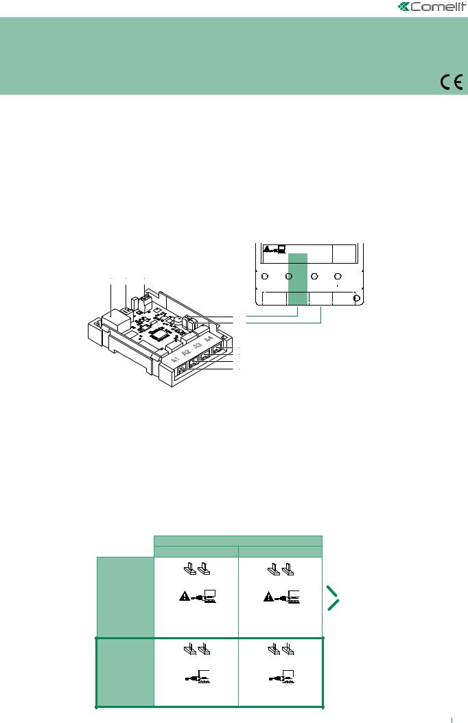
Description of Art.1456B
1 2 3
4
5
6
7
8
9
SOLO CON CAVO ROSSO COMELIT 2E7T000500
 ONLY WITH COMELIT RED CABLE 2E7T000500
|
|
|
FIXED POE |
|
|
|
|
SETTABLE |
POE |
|
|
|
N0 POE |
|
||||||||||||||
|
|
|
|
A1 |
|
|
A2 |
|
|
|
|
A3 |
|
|
|
A4 |
||||||||||||
|
|
|
|
|
|
|
|
|
|
|
|
|
||||||||||||||||
|
|
|
|
|
|
|
|
|
|
|
|
|
|
|
|
|
|
|
|
|
|
|
|
|
|
|
|
|
|
|
|
|
|
|
|
|
|
|
|
|
|
|
|
|
|
|
|
|
|
|
|
|
|
|
|
|
|
|
|
|
|
|
|
|
|
|
|
|
|
|
|
|
|
|
|
|
|
|
|
|
|
|
|
|
|
|
|
|
|
|
|
|
|
|
|
|
|
|
|
|
|
|
|
|
|
|
|
|
|
|
|
|
|
|
|
|
|
|
|
|
|
|
|
|
|
|
|
|
|
|
|
|
|
|
|
|
|
|
|
|
|
|
|
|
Art.1456B
1.Ethernet port for ViP system riser input (default addressing: Autoip).
2.Dip switches for the procedures "Reboot with predetermined network settings" on page 19 and "Restoring factory settings" on page 20.
3.Power supply input via Art. 1441, Art. 1441B.
4.CV1 and CV2 for setting port A2.
5.CV3 and CV4 for setting port A3.
6.A4 non POE Ethernet port for PC or router connection (default: Static IP address 192.168.1.200, netmask 255.255.255.0).
7.A3 non POE settable Ethernet port POE (default: Static IP address 192.168.1.200, netmask 255.255.255.0). Set the port as POE if you want to connect devices that require a power supply (door entry monitors, for example).
8.A2 non POE settable Ethernet port POE (default: Static IP address 192.168.1.200, netmask 255.255.255.0). Set the port as POE if you want to connect devices that require a power supply (door entry monitors, for example).
9.A1 Ethernet port POE (default: Static IP address 192.168.1.200, netmask 255.255.255.0).
|
SETTABLE POE |
|
|
A2 |
A3 |
|
CV1 CV2 |
CV3 CV4 |
|
POE |
POE |
SETTABLE |
|
|
|
DO NOT USE |
DO NOT USE |
|
STANDARD |
STANDARD |
|
ETHERNET* |
ETHERNET* |
|
CV1 CV2 |
CV3 CV4 |
DEFAULT |
NON POE |
NON POE |
|
|
|
|
STANDARD |
STANDARD |
|
ETHERNET |
ETHERNET |
< BACK
*Only connect to the router or PC using the red Comelit cable 2E7T000500
2
Configuration of Art.1456B
√√ This operation requires a PC loaded with the software ViP Manager version 2.3.0 or later (downloadable from the website www.
comelitgroup.com).
√√ An active internet connection is also required.
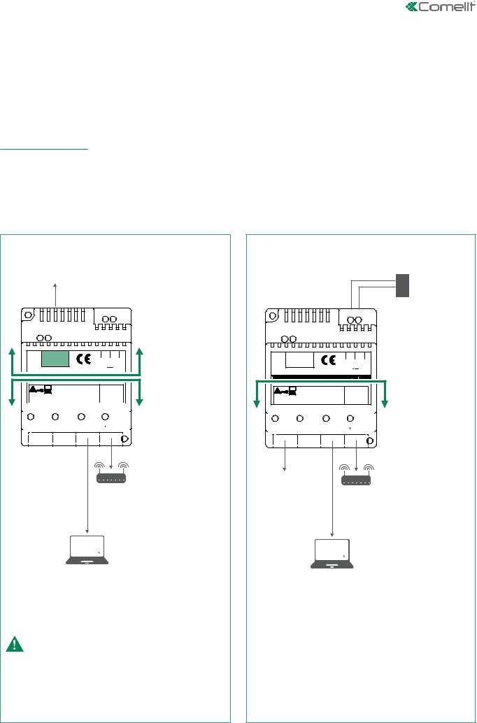
1) Connection
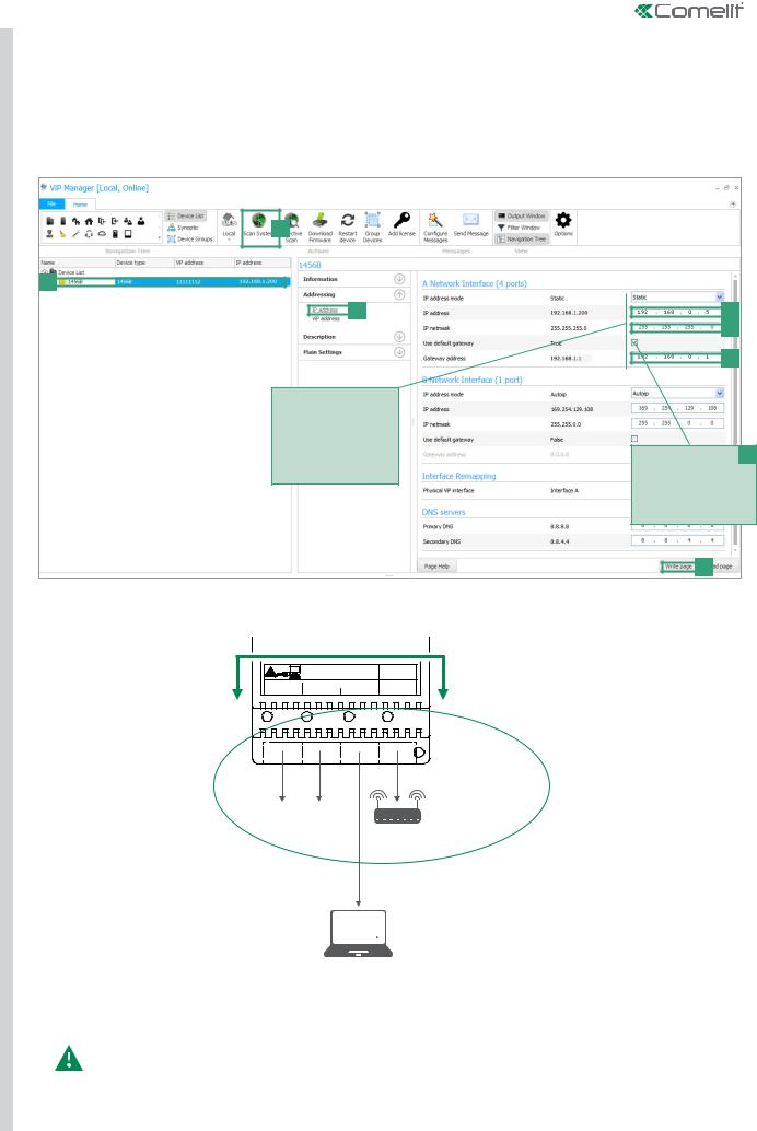
Article1456B has 2 network interfaces, A and B, labelled for easy identification, which can be configured separately to meet different system requirements. Depending on the type of system, connect the devices as shown in the following figures:
VIP NETWORK + INTERNET CONNECTION NETWORK |
|
SYSTEM WITH SINGLE NETWORK |
|
|
|
ViP SYSTEM
B |
40-56 Vdc |
INTERFACE B |
|
+ - |
|
Art.1456B |
|
IP ADDRESS AUTOIP |
ONLY WITH COMELIT RED CABLE 2E7T000500 |
|
INTERFACE A |
ONLY WITH COMELIT RED CABLE 2E7T000500 |
|
|
|
|
|
|
|
|
FIXED POE |
|
|
|
|
|
|
|
|
|
|
|
|
|
SETTABLE |
POE |
|
|
|
|
|
NON POE |
|
STATIC IP ADDRESS |
||||||||||||||||||||||||||||
|
|
|
|
|
|
|
|
A1 |
|
|
|
|
|
|
|
|
|
A2 |
|
|
|
|
|
|
|
A3 |
|
|
|
|
|
A4 |
|||||||||||||||||||||||||
|
|
|
|
|
|
|
|
|
|
|
|
|
|
|
|
|
|
|
|
|
|
|
|
|
|
|
|
|
|||||||||||||||||||||||||||||
|
|
|
|
|
|
|
|
|
|
|
|
|
|
|
|
|
|
|
|
|
|
|
|
|
|
|
|
|
|
|
|
|
|
|
|
|
|
|
|
|
|
|
|
|
|
|
|
|
|
|
|
|
|
|
|
|
192.168.1.200 (default) |
|
|
|
|
|
|
|
|
|
|
|
|
|
|
|
|
|
|
|
|
|
|
|
|
|
|
|
|
|
|
|
|
|
|
|
|
|
|
|
|
|
|
|
|
|
|
|
|
|
|
|
|
|
|
|
|
|
|
ROUTER
with active internet connection
Installer PC with ViP Manager version 2.3.0 and higher
Take particular care with regard to the network interface settings and do not configure interfaces A and B with the same addresses or similar parameters: each IP address must be unequivocal, the addresses of the interfaces A and B must not belong to the same subnet.
B |
+ - |
40-56 Vdc |
Art.1456B
ONLY WITH COMELIT RED CABLE 2E7T000500
 ONLY WITH COMELIT RED CABLE 2E7T000500
|
|
|
FIXED POE |
|
|
|
|
|
|
SETTABLE |
POE |
|
|
NON POE |
|
||||||||||||||
|
|
|
|
A1 |
|
|
|
|
A2 |
|
|
|
|
A3 |
|
|
A4 |
||||||||||||
|
|
|
|
|
|
|
|
|
|
|
|
|
|
||||||||||||||||
|
|
|
|
|
|
|
|
|
|
|
|
|
|
|
|
|
|
|
|
|
|
|
|
|
|
|
|
|
|
|
|
|
|
|
|
|
|
|
|
|
|
|
|
|
|
|
|
|
|
|
|
|
|
|
|
|
|
|
|
|
|
|
|
|
|
|
|
|
|
|
|
|
|
|
|
|
|
|
|
|
|
|
|
|
|
|
|
|
|
Art.1441
Art.1441B
INTERFACE A
STATIC IP ADDRESS
192.168.1.200 (default)
ViP SYSTEM
ROUTER
with active internet connection
Installer PC with ViP Manager version 2.3.0 and higher
All system devices form part of a single network, so it it is only necessary to configure interface A.
In this case, DO NOT alter the configuration of interface B.
< BACK |
|
3 |
|
||
|
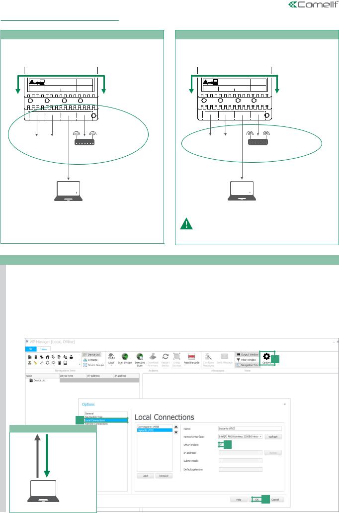
2) ViP Manager addressing
CASE 1
default address of the device (192.168.1.200) belonging to the same router network (e.g.: 192.168.1.1)
Art.1456B |
|
|
|
|
|
ONLY WITH COMELIT RED CABLE 2E7T000500 |
|
INTERFACE A |
|
|
ONLY WITH COMELIT RED CABLE 2E7T000500 |
|
|
|
FIXED POE |
A2 |
SETTABLE POE |
NON POE |
STATIC IP ADDRESS |
A1 |
A3 |
A4 |
||
|
|
|
|
192.168.1.200 (default) |
192.168.1.X
... ...
ROUTER
192.168.1.1
Installer PC
CASE 2
default address of the device (192.168.1.200) NOT belonging to the same router network (e.g.: 192.168.0.1)
Art.1456B |
|
|
|
|
|
ONLY WITH COMELIT RED CABLE 2E7T000500 |
|
INTERFACE A |
|
|
ONLY WITH COMELIT RED CABLE 2E7T000500 |
|
|
|
FIXED POE |
A2 |
SETTABLE POE |
NON POE |
STATIC IP ADDRESS |
A1 |
A3 |
A4 |
||
|
|
|
|
192.168.1.200 (default) |
... |
... |
192.168.0.X |
ROUTER
192.168.0.1
Installer PC
interface A must be assigned
a new Static IP address belonging to the same network as the devices connected to interface A
CASE 1
OBSERVE THE FOLLOWING PROCEDURE IN CASE 1
PERFORM A DHCP SYSTEM SCAN AND ASSIGN A VIP ADDRESS
Follow the procedure below to perform a system scan in DHCP, to locate all the devices connected to interfaces A and B:
•an IP address will be automatically assigned to the devices in addressing mode Autoip (connected to interface B);
•an IP address will be automatically assigned to the devices in addressing mode DHCP (connected to interface B), if the system is connected to a server with the DHCP function active;
•devices with Static IP address will be identified only if they have a network address that is compatible with that of interface A.
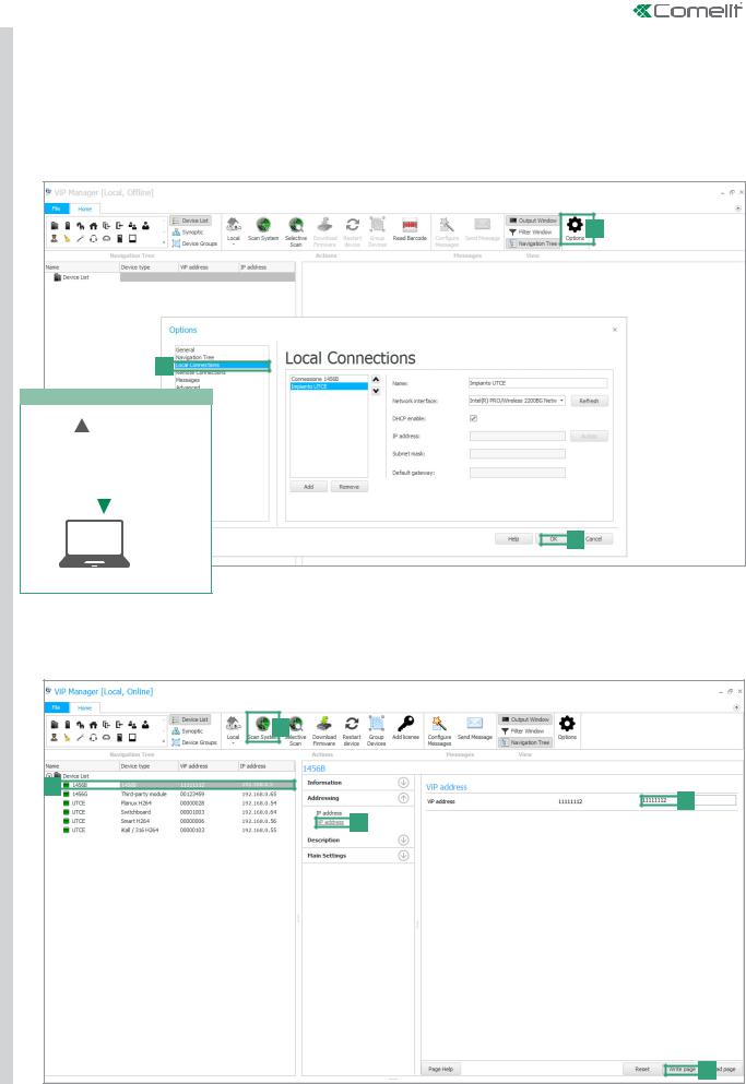
1.From Options [a] / Local connections [b] tick DHCP Enable [c] and confirm [d].
a
b
During the system scan...
AN IP COMPATIBLE
WITH THE SYSTEM c
WILL BE ASSIGNED
TO THE PC
E.G. 192.168.1.30
SYSTEM
SCAN
IN DHCP
d
Installer PC
< BACK |
|
4 |
|
||
|
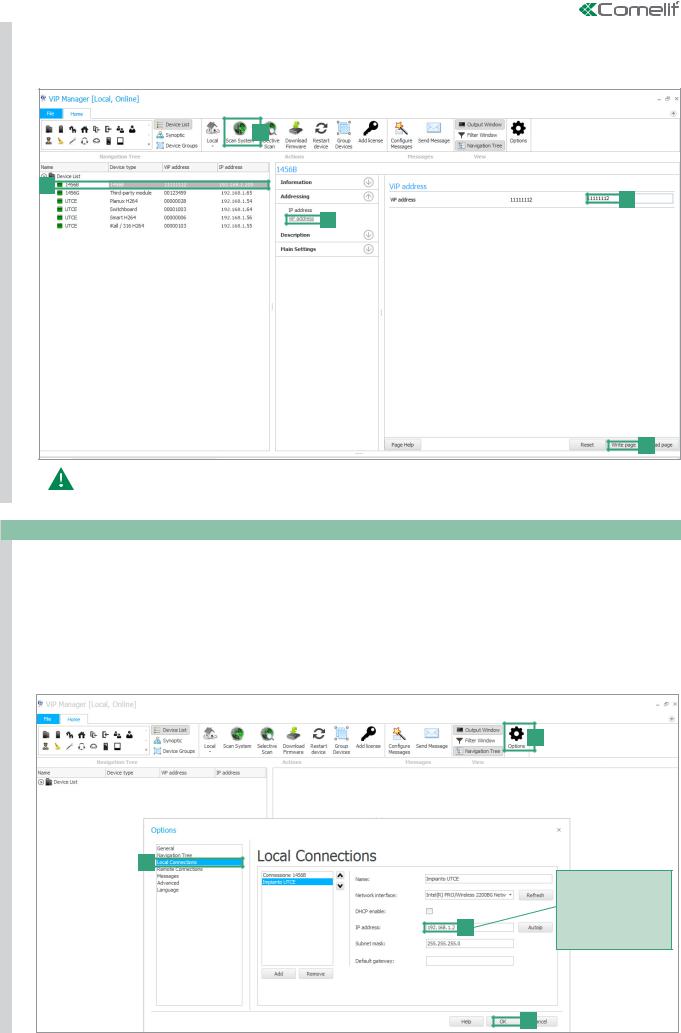
1 |
2. |
Launch the system scan by pressing Scan System [e]. |
|
CASE |
|
»» all the devices connected to the system will be displayed in the device list. |
|
3. |
Select device 1456 B [f], select Addressing/ViP address [g], assign an unequivocal ViP address to the device [h] and press Write |
||
|
|||
|
|
page [i] to save the current settings. |
e
f
h
g
i
In the case of a system with 2 1456B devices, it will be necessary to assign to interface A of one of the two devices a new Static IP address (as described in "case 2"), as each device must have a unequivocal IP address.
CASE 2
OBSERVE THE FOLLOWING PROCEDURE IN CASE 2
ASSIGN TO INTERFACE “A” A NEW Static IP address
The following procedure describes how to assign network settings to the device1456B that are compatible with those of the devices connected to interface A.
1.Open the software ViP Manager version 2.3.0 or later (downloadable from the website www.comelitgroup.com).
2.From Options [a] / Local connections [b] untick the DHCP enable box and assign an IP address to your PC [c] (in the example: 192.168.1.2)* that belongs to the same network as the IP address of interface A (default=192.168.1.200) and confirm
[d].
*the last value must be within the range of 2 to 253 excluding: 200 (assigned to the gateway Art. 1456B) and the values already assigned to other devices connected to the network.
a
b
Assign to the PC an IP address that is compatible with the network of the 1456B
c (e.g.: 192.168.1.2) so that the two devices are able to communicate
d
< BACK |
|
5 |
|
||
|
2 |
|
|
CASE |
3. |
Launch the system scan by pressing Scan System [e] |
|
»» the 1456B will appear in the device list [f] |
|
|
|
|
|
4. |
In Addressing/ IP address [g] assign device 1456B a Static IP address [h] and a IP netmask [i] compatible with the system |
|
|
for example IP: 192.168.0.5, netmask: 255.255.255.0 (warning: the IP address must not already be in use). |
|
5. |
Enable "Use default gateway" [l] ONLY for the interface connected to the router (interface A by default) |
|
6. |
Set the gateway address[m] , for example 192.168.0.1 press Write page [n] to save the current settings. |
e
f
g
Assign to device 1456 network settings that are compatible with those of the devices connected to interface A so that they can communicate.
h i
m
Enable "Use default l gateway" ONLY for the interface connected to the router (interface A by default)
n
»» device 1456B will now be in the same network as the router (192.168.0.X)
Art.1456B |
|
|
|
|
|
ONLY WITH COMELIT RED CABLE 2E7T000500 |
|
INTERFACE A |
|
|
ONLY WITH COMELIT RED CABLE 2E7T000500 |
|
|
|
FIXED POE |
A2 |
SETTABLE POE |
NON POE |
STATIC IP ADDRESS |
A1 |
A3 |
A4 |
||
|
|
|
|
192,168.0.5 |
192.168.0.X
... ...
ROUTER
192.168.0.1
Installer PC
In the cases of "ViP Network + Internet connection network" systems, take particular care with regard to the network interface settings and do not configure interfaces A and B with the same addresses or similar parameters: each IP address must be unequivocal, the addresses of the interfaces A and B must not belong to the same subnet.
< BACK |
|
6 |
|
||
|
CASE 2
PERFORM A DHCP SYSTEM SCAN AND ASSIGN A VIP ADDRESS
Follow the procedure below to perform a system scan in DHCP, to locate all the devices connected to interfaces A and B:
•an IP address will be automatically assigned to the devices in addressing mode Autoip (connected to interface B);
•an IP address will be automatically assigned to the devices in addressing mode DHCP (connected to interface A), if the system is connected to a server with the DHCP function active;
•devices with a static address will be identified only if they have a network address that is compatible with that of interface A.
1.From Options [a] / Local connections [b] tick DHCP Enable [c] and confirm [d].
a
b
During the system scan...
|
|
|
|
|
|
|
|
AN IP COMPATIBLE |
|
|
c |
|
|
WITH THE SYSTEM |
|
|
|
|
|
WILL BE ASSIGNED |
|
|
|
|
|
TO THE PC |
|
|
|
SYSTEM |
|
E.G. 192.168.0.30 |
|
|
|
|
|
|
|
|
|
SCAN |
|
|
|
|
|
IN DHCP |
|
|
|
|
|
d
Installer PC
2.Launch the system scan by pressing Scan System [e].
»»all the devices connected to the system will be displayed in the device list.
3.Select the device 1456 B [f], select Addressing/ViP address [g], assign an unequivocal ViP address to the device [h] and press Write page [i] to save the current settings.
e
f
h
g
i
< BACK |
|
7 |
|
||
|

3) Licence activation:
Activation of the licenses for each apartment allows the users of that residential unit to use the special functions provided by the device 1456B (see page 9 for further information about licenses):
•remotely answer an audio/video call from an external unit using a smartphone or tablet (master and slave license);
•answer an audio call from a GSM or landline telephone (all licenses);
•perform an audio telephone backup of an unreachable device (master and slave license);
•the possibility to dispense with a master internal unit (master license).
√√ An active internet connection is required to complete the license activation procedure.
√√ A license is needed for each apartment that wishes to make use of the functions described above.
1.Select device 1456B [a].
2.Press Add license [b].
3.Press Add license file/s [c].
4.Look for license files with the extension .viplcs [d] on the USB storage device (if supplied at time of purchase) or from the folder where it was saved when purchased and confirm by pressing Open [e].
»»a new line with the newly installed licenses will appear in the license activation wizard window.
5.Repeat steps 3 and 4 to install other licences.
6.Press Next [f],
7.enter a valid email address, press Next and confirm.
b
a
Open
Search
recent documents
Desktop
Documents
Computer resources
Filename:
Network resources File type:
d
you can select more than one file at a time
c
f
Open |
e |
Cancel |
|
»» In main settings/Licenses [g] you can view all the licenses installed[h].
h
g
< BACK |
|
8 |
|
||
|
 Loading...