


 Loading...
EN
TECHNICAL
MANUAL
Technical manual for ViP Manager software Art. 1449
www.comelitgroup.com

SOMMARIO
1 Installing ViP Manager software Art. 1449 . . . . . . . . . . . . . . . . . . . . . . . . . . . . . . . . . . . |
. |
5 |
|
1.1 |
System requirements . . . . . . . . . . . . . . . . . . . . . . . . . . . . . . . . . . . . . . . . . . |
. |
5 |
1.2 |
Installation procedure . . . . . . . . . . . . . . . . . . . . . . . . . . . . . . . . . . . . . . . . . |
. |
. 5 |
2 Description of the interface and icons . . . . . . . . . . . . . . . . . . . . . . . . . . . . . . . . . . . . |
. |
. 5 |
|
2.1 |
Home Screen . . . . . . . . . . . . . . . . . . . . . . . . . . . . . . . . . . . . . . . . . . . . . |
. |
5 |
2.2 Actions Bar . . . . . . . . . . . . . . . . . . . . . . . . . . . . . . . . . . . . . . . . . . . . . . |
. |
6 |
|
2.3 |
Display Bar . . . . . . . . . . . . . . . . . . . . . . . . . . . . . . . . . . . . . . . . . . . . . . |
. |
6 |
2.4 |
Output Window . . . . . . . . . . . . . . . . . . . . . . . . . . . . . . . . . . . . . . . . . . . . |
. |
. 6 |
2.5 |
Navigation Tree . . . . . . . . . . . . . . . . . . . . . . . . . . . . . . . . . . . . . . . . . . . . |
. |
. 7 |
2.6 |
Filter Window . . . . . . . . . . . . . . . . . . . . . . . . . . . . . . . . . . . . . . . . . . . . . |
. |
7 |
2.7 |
Navigation Bar . . . . . . . . . . . . . . . . . . . . . . . . . . . . . . . . . . . . . . . . . . . . |
. |
. 7 |
2.8 |
File Screen . . . . . . . . . . . . . . . . . . . . . . . . . . . . . . . . . . . . . . . . . . . . . . |
. |
8 |
2.9 |
Options Menu . . . . . . . . . . . . . . . . . . . . . . . . . . . . . . . . . . . . . . . . . . . . . |
. |
8 |
|
2.9.1 General Tab . . . . . . . . . . . . . . . . . . . . . . . . . . . . . . . . . . . . . . . . . . . |
. |
. 8 |
|
2.9.2 Navigation Tree Tab . . . . . . . . . . . . . . . . . . . . . . . . . . . . . . . . . . . . . . . . |
. |
9 |
|
2.9.3 Local Connections Tab . . . . . . . . . . . . . . . . . . . . . . . . . . . . . . . . . . . . . . . |
. |
9 |
|
2.9.4 Remote Connections Tab . . . . . . . . . . . . . . . . . . . . . . . . . . . . . . . . . . . . . . |
. 10 |
|
|
2.9.5 Messages Tab . . . . . . . . . . . . . . . . . . . . . . . . . . . . . . . . . . . . . . . . . . |
. |
10 |
|
2.9.6 Language . . . . . . . . . . . . . . . . . . . . . . . . . . . . . . . . . . . . . . . . . . . . |
. |
10 |
3 ViP Manager software configuration . . . . . . . . . . . . . . . . . . . . . . . . . . . . . . . . . . . . . |
. |
11 |
|
3.1 |
Creating a local connection . . . . . . . . . . . . . . . . . . . . . . . . . . . . . . . . . . . . . . . |
. 11 |
|
3.2 |
Creating a remote connection . . . . . . . . . . . . . . . . . . . . . . . . . . . . . . . . . . . . . . |
. |
11 |
3.3 |
Removing a local / remote connection . . . . . . . . . . . . . . . . . . . . . . . . . . . . . . . . . . . |
. 11 |
|
3.4 |
Configure Messages . . . . . . . . . . . . . . . . . . . . . . . . . . . . . . . . . . . . . . . . . . |
. |
11 |
4 Device management . . . . . . . . . . . . . . . . . . . . . . . . . . . . . . . . . . . . . . . . . . . . |
. 12 |
||
4.1 |
Performing Scan System . . . . . . . . . . . . . . . . . . . . . . . . . . . . . . . . . . . . . . . . |
. |
12 |
4.2 |
Performing a Selective Scan . . . . . . . . . . . . . . . . . . . . . . . . . . . . . . . . . . . . . . . |
. 12 |
|
4.3 |
Key to connected devices . . . . . . . . . . . . . . . . . . . . . . . . . . . . . . . . . . . . . . . . |
. 13 |
|
4.4 |
Internal units . . . . . . . . . . . . . . . . . . . . . . . . . . . . . . . . . . . . . . . . . . . . . |
. |
13 |
|
4.4.1 Assigning / Editing an IP address . . . . . . . . . . . . . . . . . . . . . . . . . . . . . . . . . . |
. |
13 |
|
4.4.2 Assigning / Editing a ViP address . . . . . . . . . . . . . . . . . . . . . . . . . . . . . . . . . . |
. 14 |
|
|
4.4.3 Programming buttons . . . . . . . . . . . . . . . . . . . . . . . . . . . . . . . . . . . . . . . |
. 14 |
|
|
4.4.3.1 Intercom function . . . . . . . . . . . . . . . . . . . . . . . . . . . . . . . . . . . . . . |
. 15 |
|
|
4.4.3.2 Self ignition function . . . . . . . . . . . . . . . . . . . . . . . . . . . . . . . . . . . . . . . . . . . . . . . . . . . . . . . . . . . . . . . . . . . . . . . . . |
. . 15 |
|
|
4.4.3.3 Open door function . . . . . . . . . . . . . . . . . . . . . . . . . . . . . . . . . . . . . |
. |
16 |
|
4.4.3.4 Priority Call 1 / 2 / 3 / 4 function . . . . . . . . . . . . . . . . . . . . . . . . . . . . . . . . |
. |
16 |
|
4.4.3.5 Actuator function . . . . . . . . . . . . . . . . . . . . . . . . . . . . . . . . . . . . . . |
. 17 |
|
|
4.4.3.6 Activate output function . . . . . . . . . . . . . . . . . . . . . . . . . . . . . . . . . . . |
. |
17 |
|
4.4.3.7 Privacy / Doctor / Doctor and Privacy function . . . . . . . . . . . . . . . . . . . . . . . . . . |
. 17 |
|
|
4.4.3.8 Disabled function . . . . . . . . . . . . . . . . . . . . . . . . . . . . . . . . . . . . . . |
. 17 |
|
|
4.4.4 Assigning / Editing the Device description . . . . . . . . . . . . . . . . . . . . . . . . . . . . . . |
. |
18 |
|
4.4.5 Directory management . . . . . . . . . . . . . . . . . . . . . . . . . . . . . . . . . . . . . . . |
. 18 |
|
|
4.4.5.1 Directory enable . . . . . . . . . . . . . . . . . . . . . . . . . . . . . . . . . . . . . . |
. |
18 |
|
4.4.5.2 Cameras directory . . . . . . . . . . . . . . . . . . . . . . . . . . . . . . . . . . . . . . |
. 19 |
|
|
4.4.5.3 Door status directory . . . . . . . . . . . . . . . . . . . . . . . . . . . . . . . . . . . . |
. |
19 |
|
4.4.5.4 Intercom directory . . . . . . . . . . . . . . . . . . . . . . . . . . . . . . . . . . . . . . |
. 20 |
|
|
4.4.5.5 IO modules directory . . . . . . . . . . . . . . . . . . . . . . . . . . . . . . . . . . . . |
. |
20 |
|
4.4.6 Input and output management . . . . . . . . . . . . . . . . . . . . . . . . . . . . . . . . . . . |
. |
21 |
|
4.4.6.1 NC/NO output configuration . . . . . . . . . . . . . . . . . . . . . . . . . . . . . . . . . . . . . . . . . . . . . . . . . . . . . . . . . . . . . . . . . . . |
. . 21 |
|
|
4.4.6.2 Activate output upon call . . . . . . . . . . . . . . . . . . . . . . . . . . . . . . . . . . . |
. 21 |
|
|
4.4.6.3 Input configuration . . . . . . . . . . . . . . . . . . . . . . . . . . . . . . . . . . . . . |
. |
22 |
|
4.4.7 Main settings . . . . . . . . . . . . . . . . . . . . . . . . . . . . . . . . . . . . . . . . . . . |
. 22 |
|
|
4.4.7.1 Setting the date and time . . . . . . . . . . . . . . . . . . . . . . . . . . . . . . . . . . . |
. 22 |
|
|
4.4.7.2 Brightness and contrast adjustment . . . . . . . . . . . . . . . . . . . . . . . . . . . . . . |
. |
23 |
|
4.4.7.3 Change menu language . . . . . . . . . . . . . . . . . . . . . . . . . . . . . . . . . . . |
. |
23 |
|
4.4.7.4 Setting melodies and tone repetition . . . . . . . . . . . . . . . . . . . . . . . . . . . . . . |
. 24 |
|
|
4.4.7.5 Video memory settings . . . . . . . . . . . . . . . . . . . . . . . . . . . . . . . . . . . . |
. 25 |
|
|
4.4.7.6 Message settings . . . . . . . . . . . . . . . . . . . . . . . . . . . . . . . . . . . . . . |
. 26 |
|
|
4.4.7.7 Volume settings . . . . . . . . . . . . . . . . . . . . . . . . . . . . . . . . . . . . . . . |
. 26 |
|
|
4.4.8 Special settings . . . . . . . . . . . . . . . . . . . . . . . . . . . . . . . . . . . . . . . . . . |
. 27 |
|
2

|
|
|
|
|
|
|
4.4.8.1 Setting the alarm . . . . . . . . . . . . . . . . . . . . |
. . . . . . . . . . |
. . . . . |
. . . . 27 |
|
|
4.4.8.2 Burglar alarm setting . . . . . . . . . . . . . . . . . . |
. . . . . . . . . . |
. . . . . |
. . . . 27 |
|
|
4.4.8.3 Setting call times . . . . . . . . . . . . . . . . . . . . |
. . . . . . . . . . |
. . . . . |
. . . . 28 |
|
|
4.4.8.4 Setting device behaviour . . . . . . . . . . . . . . . . . |
. . . . . . . . . . |
. . . . . |
. . . . 29 |
|
|
4.4.8.5 Divert call setting . . . . . . . . . . . . . . . . . . . . |
. . . . . . . . . . |
. . . . . |
. . . . 29 |
|
|
4.4.8.6 Setting the installer password . . . . . . . . . . . . . . . |
. . . . . . . . . . |
. . . . . |
. . . . 30 |
|
|
4.4.8.9 Setting the video bitrate . . . . . . . . . . . . . . . . . |
. . . . . . . . . . |
. . . . . |
. . . . 30 |
|
|
4.5 Porter switchboard . . . . . . . . . . . . . . . . . . . . . . . . . |
. . . . . . . . . . |
. . . . . |
. . . . 31 |
|
|
4.5.1 Assigning / Editing the IP address . . . . . . . . . . . . . . . . |
. . . . . . . . . . |
. . . . . |
. . . . 31 |
|
|
4.5.2 Assigning / Editing the ViP address . . . . . . . . . . . . . . . |
. . . . . . . . . . |
. . . . . |
. . . . 31 |
|
|
4.5.3 Programming buttons . . . . . . . . . . . . . . . . . . . . . |
. . . . . . . . . . |
. . . . . |
. . . . 32 |
|
|
4.5.3.1 Intercom function . . . . . . . . . . . . . . . . . . . . |
. . . . . . . . . . |
. . . . . |
. . . . 32 |
|
|
4.5.3.2 Self ignition function . . . . . . . . . . . . . . . . . . . . . . . . . . . . . . . . . . . . . |
. . . . . . . . . . . . . . . . . . . . |
. . . . . . . . . . |
. . . . . . . . 33 |
|
|
4.5.3.3 Open door function . . . . . . . . . . . . . . . . . . . |
. . . . . . . . . . |
. . . . . |
. . . . 33 |
|
|
4.5.3.4 Actuator function . . . . . . . . . . . . . . . . . . . . |
. . . . . . . . . . |
. . . . . |
. . . . 33 |
|
|
4.5.4 Day and Night function . . . . . . . . . . . . . . . . . . . . . |
. . . . . . . . . . |
. . . . . |
. . . . 34 |
|
|
4.5.4.1 Enabling / disabling Day and Night function . . . . . . . . . |
. . . . . . . . . . |
. . . . . |
. . . . 34 |
|
|
4.5.4.1 Setting the device list . . . . . . . . . . . . . . . . . . |
. . . . . . . . . . |
. . . . . |
. . . . 34 |
|
|
4.5.4.1 Weekly programming . . . . . . . . . . . . . . . . . . |
. . . . . . . . . . |
. . . . . |
. . . . 35 |
|
|
4.5.5 Assigning / Editing the Device description . . . . . . . . . . . . |
. . . . . . . . . . |
. . . . . |
. . . . 35 |
|
|
4.5.6 Directory management . . . . . . . . . . . . . . . . . . . . . |
. . . . . . . . . . |
. . . . . |
. . . . 36 |
|
|
4.5.6.1 Apartments directory . . . . . . . . . . . . . . . . . . |
. . . . . . . . . . |
. . . . . |
. . . . 36 |
|
|
4.5.6.2 Cameras directory . . . . . . . . . . . . . . . . . . . . |
. . . . . . . . . . |
. . . . . |
. . . . 36 |
|
|
4.5.6.3 Cps directory . . . . . . . . . . . . . . . . . . . . . . |
. . . . . . . . . . |
. . . . . |
. . . . 37 |
|
|
4.5.6.4 Door status directory . . . . . . . . . . . . . . . . . . |
. . . . . . . . . . |
. . . . . |
. . . . 37 |
|
|
4.5.6.5 IO modules directory . . . . . . . . . . . . . . . . . . |
. . . . . . . . . . |
. . . . . |
. . . . 38 |
|
|
4.5.6.6 Panels directory . . . . . . . . . . . . . . . . . . . . |
. . . . . . . . . . |
. . . . . |
. . . . 38 |
|
|
4.5.7 Main settings . . . . . . . . . . . . . . . . . . . . . . . . . |
. . . . . . . . . . |
. . . . . |
. . . . 39 |
|
|
4.5.7.1 Setting the date and time . . . . . . . . . . . . . . . . . |
. . . . . . . . . . |
. . . . . |
. . . . 39 |
|
|
4.5.7.2 Changing the menu language . . . . . . . . . . . . . . . |
. . . . . . . . . . |
. . . . . |
. . . . 39 |
|
|
4.5.7.3 Message client settings . . . . . . . . . . . . . . . . . |
. . . . . . . . . . |
. . . . . |
. . . . 40 |
|
|
4.5.7.4 Targets for call diversion . . . . . . . . . . . . . . . . . |
. . . . . . . . . . |
. . . . . |
. . . . 41 |
|
|
4.5.8 Services . . . . . . . . . . . . . . . . . . . . . . . . . . . |
. . . . . . . . . . |
. . . . . |
. . . . 41 |
|
|
4.5.8.1 Message server settings . . . . . . . . . . . . . . . . . |
. . . . . . . . . . |
. . . . . |
. . . . 41 |
|
|
4.5.8.2 Remote configuration . . . . . . . . . . . . . . . . . . |
. . . . . . . . . . |
. . . . . |
. . . . 42 |
|
|
4.5.9 Special settings . . . . . . . . . . . . . . . . . . . . . . . . |
. . . . . . . . . . |
. . . . . |
. . . . 42 |
|
|
4.5.9.1 Associated camera . . . . . . . . . . . . . . . . . . . |
. . . . . . . . . . |
. . . . . |
. . . . 42 |
|
|
4.5.9.2 Setting call times . . . . . . . . . . . . . . . . . . . . |
. . . . . . . . . . |
. . . . . |
. . . . 43 |
|
|
4.5.9.2 Open door setting . . . . . . . . . . . . . . . . . . . . |
. . . . . . . . . . |
. . . . . |
. . . . 43 |
|
|
4.5.9.3 Setting the installer password . . . . . . . . . . . . . . . |
. . . . . . . . . . |
. . . . . |
. . . . 44 |
|
|
4.5.9.4 Enabling / disabling the ON-OFF button . . . . . . . . . . . |
. . . . . . . . . . |
. . . . . |
. . . . 44 |
|
|
4.5.9.5 Configuring priority call names . . . . . . . . . . . . . . |
. . . . . . . . . . |
. . . . . |
. . . . 45 |
|
|
4.5.9.6 Configuring the self ignition key . . . . . . . . . . . . . . |
. . . . . . . . . . |
. . . . . |
. . . . 45 |
|
|
4.5.9.7 Setting the video bitrate . . . . . . . . . . . . . . . . . |
. . . . . . . . . . |
. . . . . |
. . . . 46 |
|
|
4.6 External units and directories . . . . . . . . . . . . . . . . . . . . |
. . . . . . . . . . |
. . . . . |
. . . . 46 |
|
|
4.6.1 Assigning / Editing the IP address . . . . . . . . . . . . . . . . |
. . . . . . . . . . |
. . . . . |
. . . . 46 |
|
|
4.6.2 Assigning / Editing the ViP address . . . . . . . . . . . . . . . |
. . . . . . . . . . |
. . . . . |
. . . . 47 |
|
|
4.6.3 Programming buttons . . . . . . . . . . . . . . . . . . . . . |
. . . . . . . . . . |
. . . . . |
. . . . 47 |
|
4.6.3.1Programming buttons on board the external unit . . . . . . . . . . . . . . . . . . . . . . . . . . 47
4.6.3.2Programming the additional button module . . . . . . . . . . . . . . . . . . . . . . . . . . . . . . . . . . . . . . . . . . . . . . . . . . . . . . . . 48
4.6.4 Assigning / Editing the Device description . . . . . . . . . . . . . . . . . . . . . . . . . . . . . . . |
48 |
4.6.5 Directories Art. 3360A and Art. 3370 . . . . . . . . . . . . . . . . . . . . . . . . . . . . . . . . . . |
49 |
4.6.5.1 Name directory management . . . . . . . . . . . . . . . . . . . . . . . . . . . . . . . . . . |
49 |
4.6.5.2Door open passwords directory management . . . . . . . . . . . . . . . . . . . . . . . . . . . 49
4.6.5.3Parameter management for directories Art. 3360A and Art. 3370 . . . . . . . . . . . . . . . . . . . 50
4.6.5.4 Example of how to use the Dial pattern function . . . . . . . . . . . . . . . . . . . . . . . . . . |
51 |
4.6.6 Input and output management . . . . . . . . . . . . . . . . . . . . . . . . . . . . . . . . . . . . |
52 |
4.6.6.1 Actuator on self-ignition . . . . . . . . . . . . . . . . . . . . . . . . . . . . . . . . . . . . |
52 |
4.6.6.2 Configuring input 1 . . . . . . . . . . . . . . . . . . . . . . . . . . . . . . . . . . . . . . |
52 |
4.6.6.3 Configuring actuator IO modules . . . . . . . . . . . . . . . . . . . . . . . . . . . . . . . . |
54 |
4.6.6.4 Configuring porter relay 2 . . . . . . . . . . . . . . . . . . . . . . . . . . . . . . . . . . . |
55 |
4.6.6.5 Configuring the external unit relays . . . . . . . . . . . . . . . . . . . . . . . . . . . . . . . |
55 |
3

|
|
|
|
|
|
|
4.6.7 Main settings . . . . . . . . . . . . . . . . . . . . . . . . . . . . . . . . . . . . . . . . . . . |
. 56 |
|
|
|
4.6.7.1 Changing the voice message language . . . . . . . . . . . . . . . . . . . . . . . . . . . . . |
. 56 |
|
|
|
4.6.8 Special settings . . . . . . . . . . . . . . . . . . . . . . . . . . . . . . . . . . . . . . . . . . |
. 56 |
|
|
|
4.6.8.1 Special settings . . . . . . . . . . . . . . . . . . . . . . . . . . . . . . . . . . . . . . . |
. 56 |
|
|
|
4.6.8.2 Setting the video bitrate . . . . . . . . . . . . . . . . . . . . . . . . . . . . . . . . . . . . |
57 |
|
|
|
4.6.8.3 Video replicast . . . . . . . . . . . . . . . . . . . . . . . . . . . . . . . . . . . . . . . . |
58 |
|
4.7 |
Camera interface module Art. 1445 . . . . . . . . . . . . . . . . . . . . . . . . . . . . . . . . . . . . |
. 59 |
||
|
|
4.7.1 Assigning / Editing the IP address . . . . . . . . . . . . . . . . . . . . . . . . . . . . . . . . . . |
. 59 |
|
|
|
4.7.2 Assigning / Editing the ViP address . . . . . . . . . . . . . . . . . . . . . . . . . . . . . . . . . . |
59 |
|
|
|
4.7.3 Assigning / Editing the Device description . . . . . . . . . . . . . . . . . . . . . . . . . . . . . . . |
60 |
|
|
|
4.7.4 Main settings . . . . . . . . . . . . . . . . . . . . . . . . . . . . . . . . . . . . . . . . . . . |
. 60 |
|
|
|
4.7.4.1 Camera parameters . . . . . . . . . . . . . . . . . . . . . . . . . . . . . . . . . . . . . . |
60 |
|
|
|
4.7.5 Special settings . . . . . . . . . . . . . . . . . . . . . . . . . . . . . . . . . . . . . . . . . . |
. 61 |
|
|
|
4.7.5.1 Setting the video bitrate . . . . . . . . . . . . . . . . . . . . . . . . . . . . . . . . . . . . |
61 |
|
|
|
4.7.5.2 Video replicast . . . . . . . . . . . . . . . . . . . . . . . . . . . . . . . . . . . . . . . . |
61 |
|
4.8 |
IO module Art. 1443 . . . . . . . . . . . . . . . . . . . . . . . . . . . . . . . . . . . . . . . . . . . |
62 |
||
|
|
4.8.1 Assigning / Editing the IP address . . . . . . . . . . . . . . . . . . . . . . . . . . . . . . . . . . |
. 62 |
|
|
|
4.8.2 Assigning / Editing the ViP address . . . . . . . . . . . . . . . . . . . . . . . . . . . . . . . . . . |
62 |
|
|
|
4.8.3 Assigning / Editing the Device description . . . . . . . . . . . . . . . . . . . . . . . . . . . . . . . |
63 |
|
|
|
4.8.4 Input and output settings . . . . . . . . . . . . . . . . . . . . . . . . . . . . . . . . . . . . . . |
. 63 |
|
|
|
4.8.4.1 Configuring Inputs 1 and 2 . . . . . . . . . . . . . . . . . . . . . . . . . . . . . . . . . . . |
63 |
|
|
|
4.8.4.2 Configuring the outputs . . . . . . . . . . . . . . . . . . . . . . . . . . . . . . . . . . . . |
65 |
|
|
5 Using the ViP Manager software functions . . . . . . . . . . . . . . . . . . . . . . . . . . . . . . . . . . . |
66 |
||
5.1 |
Creation of a synoptic diagram . . . . . . . . . . . . . . . . . . . . . . . . . . . . . . . . . . . . . . |
. 66 |
||
5.2 |
Creation of a device group . . . . . . . . . . . . . . . . . . . . . . . . . . . . . . . . . . . . . . . . |
66 |
||
5.3 |
Sending messages . . . . . . . . . . . . . . . . . . . . . . . . . . . . . . . . . . . . . . . . . . . |
. 67 |
||
5.4 |
Read barcode procedure . . . . . . . . . . . . . . . . . . . . . . . . . . . . . . . . . . . . . . . . . |
68 |
||
5.5 |
Device firmware download procedure . . . . . . . . . . . . . . . . . . . . . . . . . . . . . . . . . . . |
. 68 |
||
5.6 |
Compare function . . . . . . . . . . . . . . . . . . . . . . . . . . . . . . . . . . . . . . . . . . . . |
69 |
||
|
Glossary . . . . . . . . . . . . . . . . . . . . . . . . . . . . . . . . . . . . . . . . . . . . . . . . . . |
70 |
||
4
1 Installing ViP Manager software Art. 1449
1.1 System requirements
◊Windows XP operating system or higher.
◊Network card or wi-fi card.
◊Ethernet cable for connection of Switch Art. 1440 to PC (supplied with software art. 1449).
1.2 Installation procedure
1.Run the setup program for the ViP Manager software Art. 1449 (this can be found on the CD).
2.Follow the instructions on the screen until installation is complete.
2 Description of the interface and icons
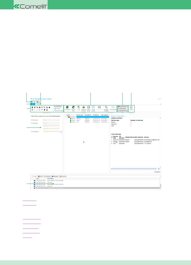
2.1 Home Screen
11 |
1 |
2 |
3 |
4 |
10
9
8
7 |
|
|
|
5 |
|
|
6
1.Home Tab: tab for accessing the main software screen
2.Actions Bar: group of icons which perform specific actions
3.Display Bar: group of icons used to enable / disable software window display
4.Options Icon: icon used to access the software Options menu
5.System Composition: the content of this window changes depending on the procedure in progress
6.Output Window: window displaying various system diagnostics messages
7.Navigation Tree: window used to navigate between the devices connected to the system
8.Filter Window: window used to filter the list of devices connected to the system
9.Navigation Bar: group of icons used to change the Navigation Tree display mode
10.File Tab: tab for accessing the software File menu
11.Shortcut Bar: group of icons used to start functions quickly System Scan, Options Menu and Exit
CONTENTS
5
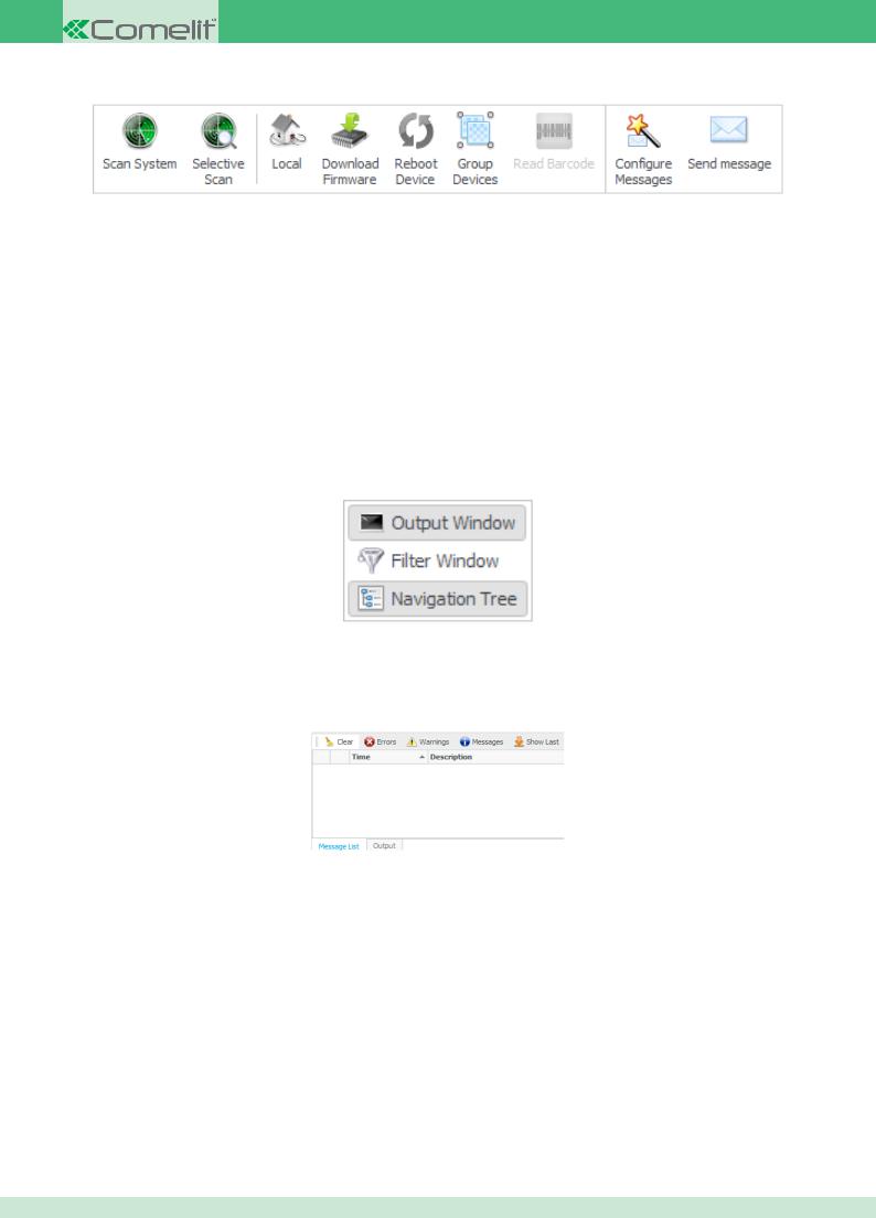
2.2 Actions Bar
◊Scan System: when this icon is clicked, the software will search for all devices connected to the system and will list them in the Navigation Window
◊Selective Scan: as Scan System, but filtering the search as described in chapter Performing a Selective Scan
◊Local / Remote: clicking this icon switches from Local Mode to Remote Mode or vice-versa
◊Download Firmware: clicking this icon will start the Firmware download process for the device selected in the Navigation Window
◊Reboot Device: clicking this icon will reboot the device selected in the Navigation Window
◊Group Devices: clicking this icon will create a new group containing the devices selected in the Navigation Window
◊Read Barcode: clicking this icon will start the Read Barcode process for a device
◊Configure Messages: clicking this icon opens the Configure Messages menu
◊Send Message: clicking this icon opens the Send Message menu
2.3 Display Bar
◊Output Window: clicking this icon enables / disables the Output Window display
◊Filter Window: clicking this icon enables / disables the Filter Window display
◊Navigation Tree: clicking this icon enables / disables the Navigation Tree display
2.4 Output Window
◊Delete: clicking this icon deletes all messages in the window
◊Errors: clicking this icon enables / disables the displaying of “Error” messages
◊Warnings: clicking this icon enables / disables the displaying of “Warning” messages
◊Messages: clicking this icon enables / disables the displaying of “Message” type messages
◊Show Last: clicking this icon automatically scrolls through the chronology until the last message received is reached
CONTENTS
6
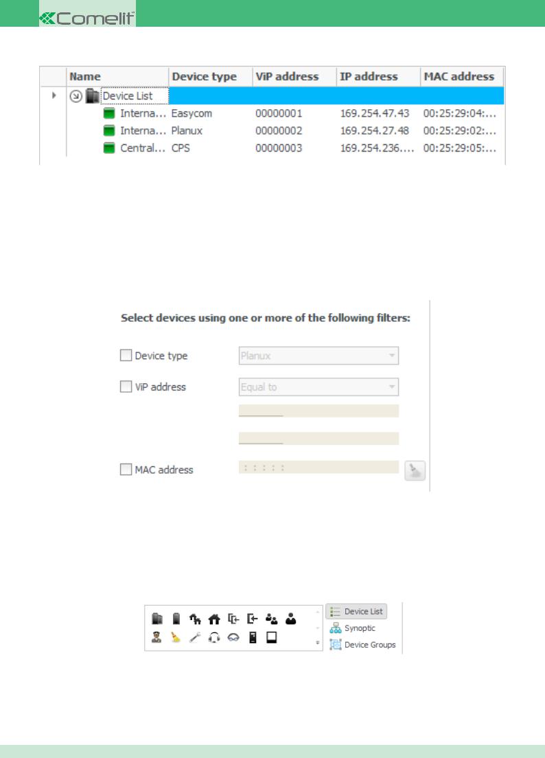
2.5 Navigation Tree
◊Name: column listing the devices present in the system. This column offers access to the specific device functions / settings
◊Device type: shows the type of device (factory-set parameter, cannot be changed)
◊ViP address: shows the ViP address assigned to the device
◊IP address: shows the IP address assigned to the device
◊MAC address: shows the MAC address assigned to the device (factory-set parameter, cannot be changed)
2.6 Filter Window
This window can be used to filter the list of devices connected to the system, so that only the desired entries are displayed.
◊ Device type: this parameter is used to filter the list by the type of device. The various devices in the ViP range can be selected using a drop-down menu
◊ ViP address: this parameter is used to filter the list, with the ViP address assigned to the devices connected to the system used as a reference.
The various parameters "Equal to", "Greater than", "Less than" and "Between" can be selected using a drop-down menu
◊ MAC address: this parameter is used to filter the list, with the MAC addressof the devices used as a reference
2.7 Navigation Bar
◊Device List: displays all the devices connected to the system
◊Synoptic: menu used to create a synoptic diagram of a system with the devices connected
◊Device Groups: displays all device groups created
CONTENTS
7
2.8 File Screen
7 |
8 |
9 |
10 11 |
12 |
1
2
3
4
5
6
1.New: used to create a new system by means of the Read Barcode procedure
2.Save Selection: used to save the settings for the devices
selected in the Navigation Tree window
3. Save All: used to save the settings for the devices currently connected to the system
4. Compare: used to compare the settings for devices currently connected to the system with those contained in a previously saved file
5.Download: used to load device settings from a previously saved file
6.Exit: exits the program
7.ViP Manager Help: opens the software use help section
8.Options: opens the Options Menu
9.Export options: exports all the application settings by saving
them in a file
10. Import options: loads all the settings saved using the "Export options" function
11. Check for Updates: the software checks for a more recent version online (internet connection required)
12. Version: indicates the software version in use
2.9 Options Menu
The Options Menu can be used to configure all parameters for the ViP Manager software Art. 1449. All possible options are explained in detail below.
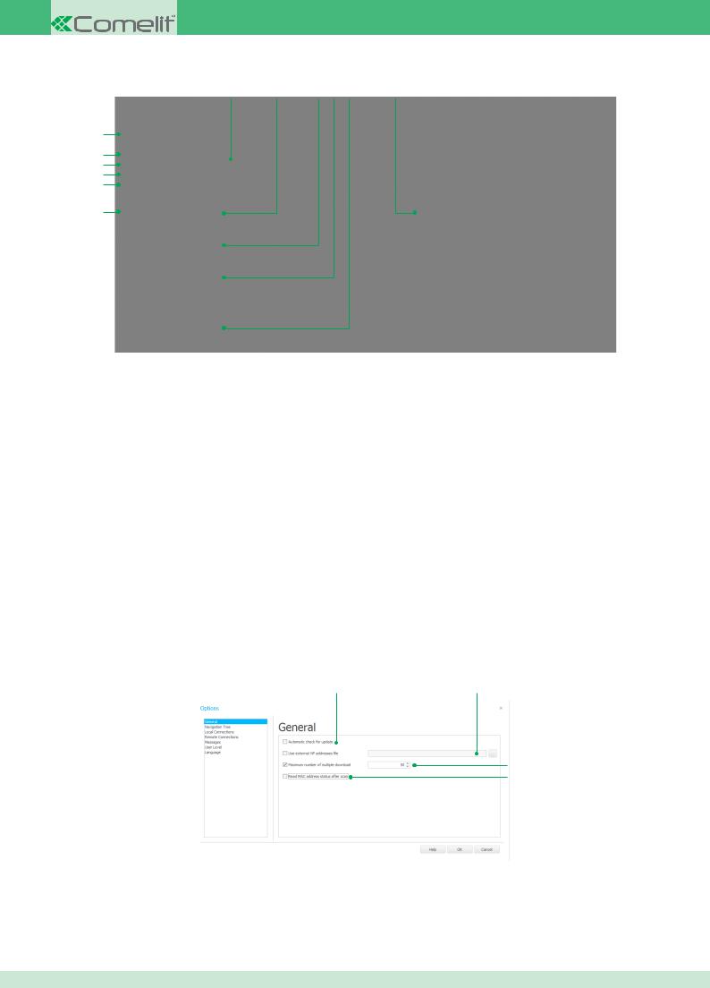
2.9.1 General Tab
1 |
2 |
3
4
1. Automatic check for update: if this option is ticked, at startup the ViP Manager software will automatically check for any updates on the network (internet connection required)
2.Use external ViP addresses file:
3.Maximum number of multiple download: max. number of devices that can be updated at the same time
4.Read MAC address status after scan:
CONTENTS
8
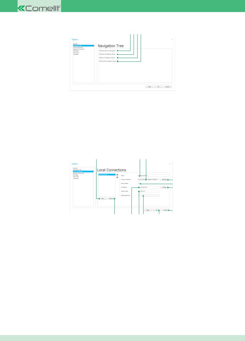
2.9.2 Navigation Tree Tab
1 2 3 4
1.Show Device Type Column: this tick enables / disables the Device Type column display in the Navigation Tree window
2.Show ViP Address Column: this tick enables / disables the ViP address column display in the Navigation Treewindow
3.Show IP Address Column: this tick enables / disables the IP address column display in the Navigation Tree window
4.Show MAC Address Column: this tick enables / disables the MAC address column display in the Navigation Treewindow
2.9.3 Local Connections Tab
1 |
2 |
3 |
4
5
6
7
12 |
11 |
10 |
9 |
8 |
1.Add button: adds a new connection
2.Name box: box used to change the name of the selected connection
3.Network interface box: drop-down menu with a list of available network interfaces (select the entry you wish to use for the currently selected
connection)
4.Refresh button: refreshes the list of available network interfaces
5.DHCP enable: enables the DHCP function only if the system is connected to a server with the DHCP function enabled
6.Autoip button: assigns an IP address to the connection automatically
7.Cancel button: exits the Options menu without saving the changes made
8.OK button: saves the changes made and exits the Options menu
9.Default Gateway box: box displaying the Default Gateway assigned to the selected connection
10.Subnet Mask box: box displaying the Subnet Mask assigned to the selected connection. The address can be changed manually if you wish to
assign a specific one to the connection
11. IP address box: box displaying the IP address currently assigned to the connection. The address can be changed manually if you wish to assign a specific one to the connection
12. Remove button: deletes the selected connection from the list of available connections
CONTENTS
9
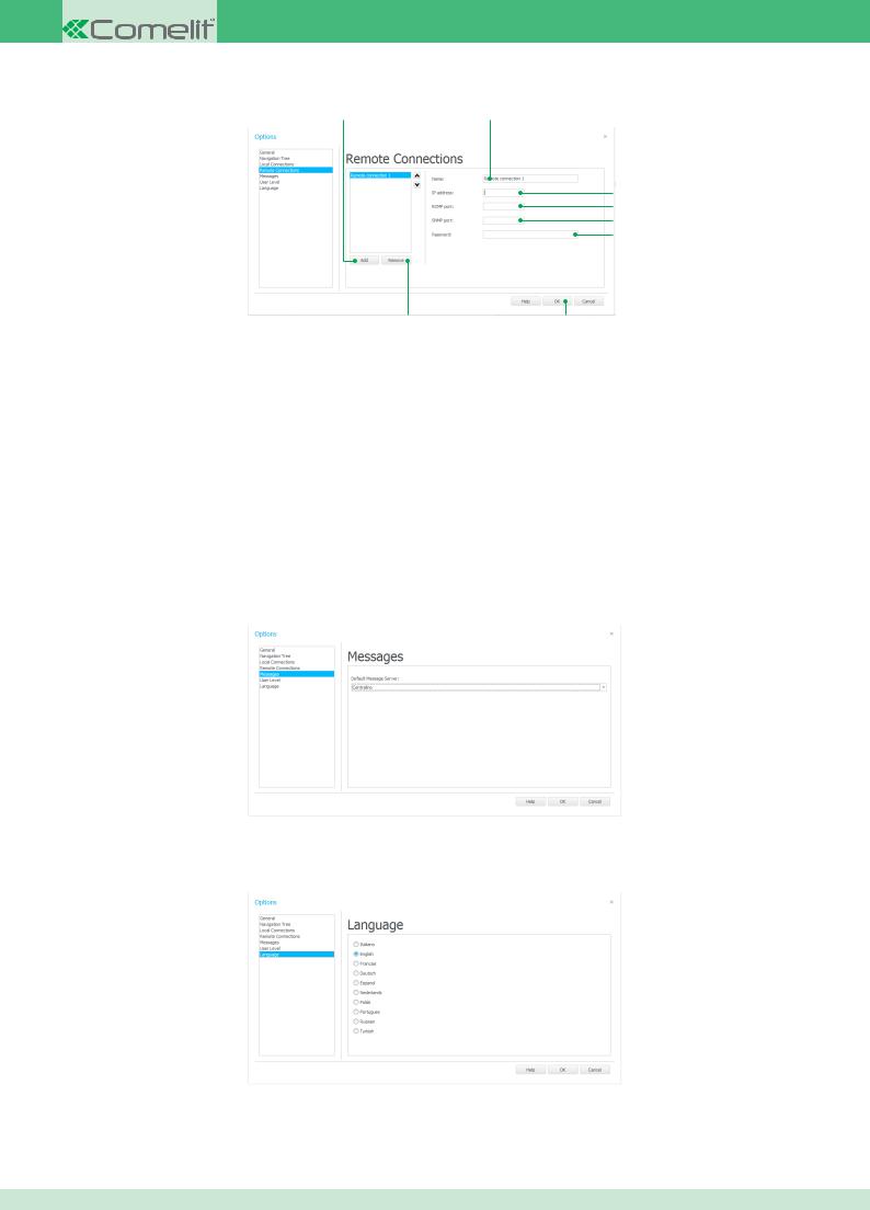
2.9.4 Remote Connections Tab
1 |
2 |
3
4
5
6
 7
7
9 |
8 |
1.Add button: adds a new connection
2.Name box: box used to change the name of the selected connection
3.IP address box: box used to enter the IP address of the router for the system to which you wish to connect
4.RCMP port box: box used to enter the number of the RCMP port on the router set up for ViP Manager software connection
5.SNMP port box: box used to enter the number of the SNMP port on the router set up for ViP Manager software connection
6.Password: box used to enter the password set on the switchboard during system configuration for remote connections
7.Cancel button: exits the Options menu without saving the changes made
8.OK button: saves the changes made and exits the Options menu
9.Remove button: deletes the selected connection from the list of available connections
2.9.5 Messages Tab
1. Default Message Server: this box is used to select the device to be set as the default message server
2.9.6 Language
1. Language: used to change the ViP Manager software language
CONTENTS
10
3 ViP Manager software configuration
3.1 Creating a local connection
In order to use the ViP Manager software, you first need to establish a connection between the PC and the system. The procedure used to set up this connection when the PC and system are on the same network is described below.
1.Access the Options menu
2.Open the Local Connections Tab
3.Press “Add”
4.In the “Name” box, enter the name you wish to assign to the connection (e.g. System name)
5.Use the “Network interface” drop-down menu to select the network card for your PC (if several cards are installed, select the one to which the network cable is connected)
6.Select DHCP only if the system has been connected to a server with DHCP protocol enabled. Press “Autoip” to assign an IP address to your PC (the IPAddress, Subnet Mask and Default Gateway boxes will be filled in automatically by the software)
7.Press “OK” to save and exit the Options menu.
3.2 Creating a remote connection
In order to use the ViP Manager software, you first need to establish a connection between the PC and the system. The procedure used to set up this connection when the PC and system are on different networks is described below.
Both networks must have internet access
Make sure that the system has been configured for remote connections
1.Access the Options menu
2.Open the Remote Connections Tab
3.Press “Add”
4.In the “Name” box, enter the name you wish to assign to the connection (e.g. system name)
5.In the “IP address” box, enter the IP address of the router connected to the system
6.In the “RCMP” box, enter the number of the RCMP port on the router connected to the system set up for ViP Manager software connection
7.In the “SNMP” box, enter the number of the SNMP port on the router connected to the system set up for ViP Manager software connection
8.In the “Password” box, enter the password set on the switchboard during system configuration for remote connections
3.3 Removing a local / remote connection
To remove a local or remote connection created previously, proceed as follows.
1.Access the Options menu
2.Open the Local Connections / Remote Connections Tab
3.Select the connection you wish to remove
4.Press “Remove”
5.Press “OK” to save and exit the Options menu.
3.4 Configure Messages
 Using this function requires the creation of a synoptic diagram
In order to use the Send Message function, you must first set a suitable device (e.g. switchboard, PC) as the message server.
1.Click the “Configure Messages” icon in theActions Bar
2.Select the device(s) you wish to use as a message server by ticking the box on the right-hand side
3.Click “Next”
4.Link a server to the buildings listed
5.Click “Next”
6.A screen summarising the settings will appear
7.Click “End” to save and end the configuration procedure, or “Cancel” to cancel.
CONTENTS
11
4 Device management
4.1 Performing Scan System
When Scan System is performed, all powered devices connected to the system are displayed.
`` To perform Scan System, click the icon:
Once the device search is complete, the Navigation Tree window shows all the powered devices connected to the system.
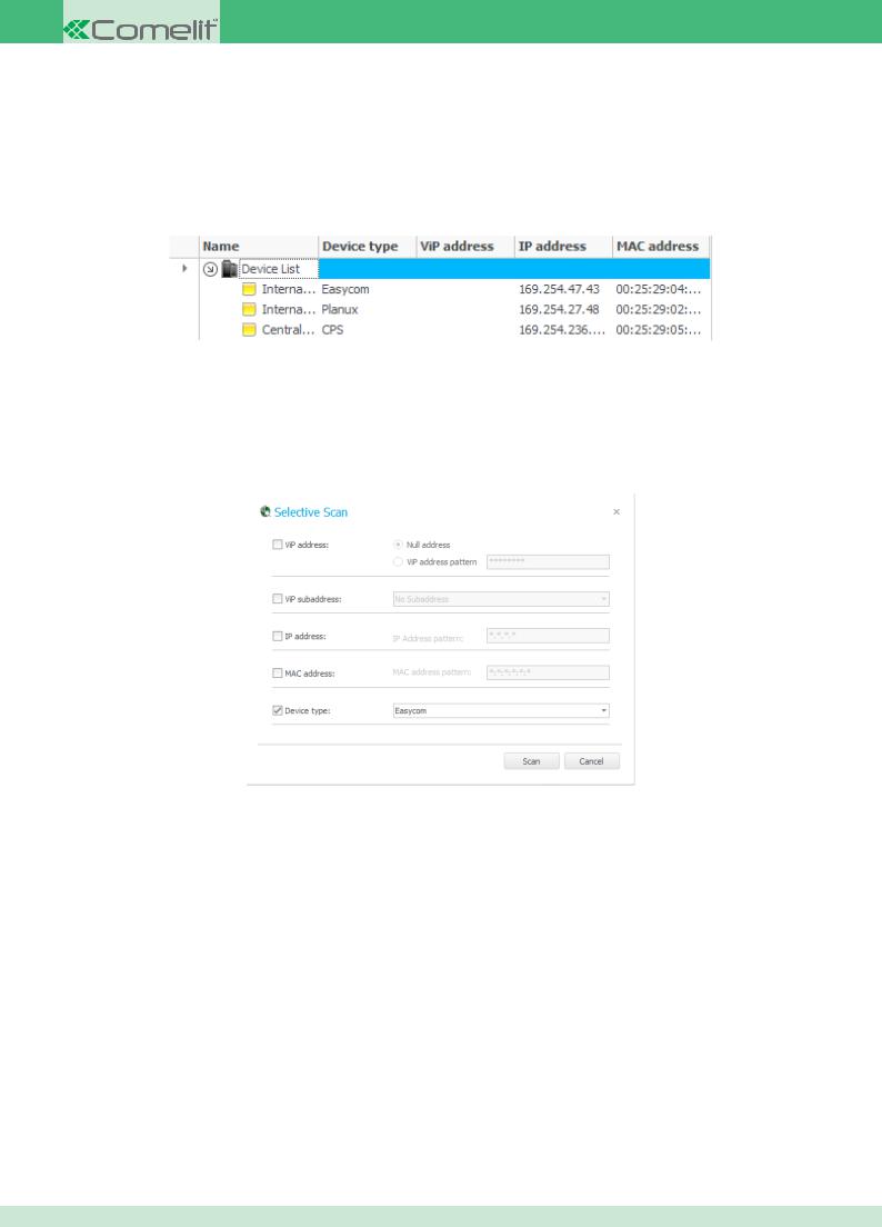
4.2 Performing a Selective Scan
The Selective Scan option is used to apply filters in order to search for devices within specific parameters. To perform a Selective Scan, proceed as follows:
1.Click on the icon:
2.Customise the filter screen to view the relevant devices.
The available filters are:
◊ViP address
•Null address: search for all devices to which a ViP address has NOT been assigned
•ViP address pattern: search for all devices for which a ViP address has NOT been entered
◊ViP subaddress
•No subaddress: search for all devices to which a subaddress has NOT been assigned (e.g. external units)
•Master only: search for all devices set as Master
•Slaves only: search for all devices set as Slave
•Master and Slaves: search for all devices set as Master and Slave
◊IP address
•IPAddress pattern: search for the device with the IP address specified in this filter
◊MAC address
•MAC address pattern: search for the device with the MAC address specified in this filter
◊Device type: the specific type of device in the ViP range can be selected using a drop-down menu
3. Click “Scan” to start searching for devices
N.B. The asterisk character can be used within the boxes as a wild card. For example, if we enter the pattern '5******1' in the ViP address search box, the system will search for all devices which have a ViP address starting with 5 and ending with 1.
CONTENTS
12
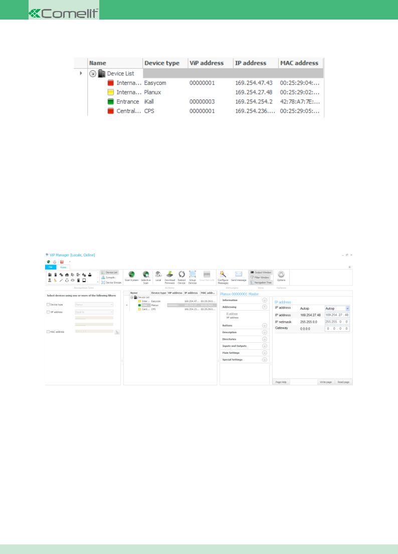
4.3 Key to connected devices
In the Navigation Tree window the connected devices are preceded by an icon indicating the ViP address status.
◊Green: the ViP address of the device is configured correctly
◊Yellow: a ViP address has not been assigned to the device
◊Red: two Master or Slave devices have been programmed with the same ViP address
◊Purple: the device is in boot mode. This scenario occurs if the connection was cut off during device updating and the procedure was not completed properly. In this case, carry out the Firmware download procedure
4.4 Internal units
The ViP system includes 2 types of internal unit, video internal units (Planux, 7 Stelle, Smart and Maestro) and audio internal units (Easycom). This chapter lists all the configuration parameters for both device types. We must stress that not all functions can be located on all devices. The devices which are compatible with the function described are listed at the start of each paragraph.
4.4.1 Assigning / Editing an IP address
ALL DEVICES
To assign or edit the IP address of an internal unit, proceed as follows:
1.Select the internal unit by clicking on the navigation tree
2.Expand the “Addressing” menu
3.Enter the “IP address” sub-menu
4.Use the drop-down menu to select the IP address mode (Autoip, Static or DHCP)
5.Depending on the mode selected in the previous step, the “IP address”, “IP netmask” and “Gateway address” boxes will need to be filled in
6.Click “Write page” to apply the settings
CONTENTS
13
4.4.2 Assigning / Editing a ViP address
ALL DEVICES
To assign or edit the ViP address of an internal unit, proceed as follows:
1.Select the internal unit by clicking on the navigation tree
2.Expand the “Addressing” menu
3.Enter the “ViP address” sub-menu
4.Enter the ViP address you wish to assign to the device in the relevant box
5.Choose whether to set the device as Master or Slave using the drop-down menu
6.Click “Write page” to apply the settings
 MAX 1 master device for each ViP address
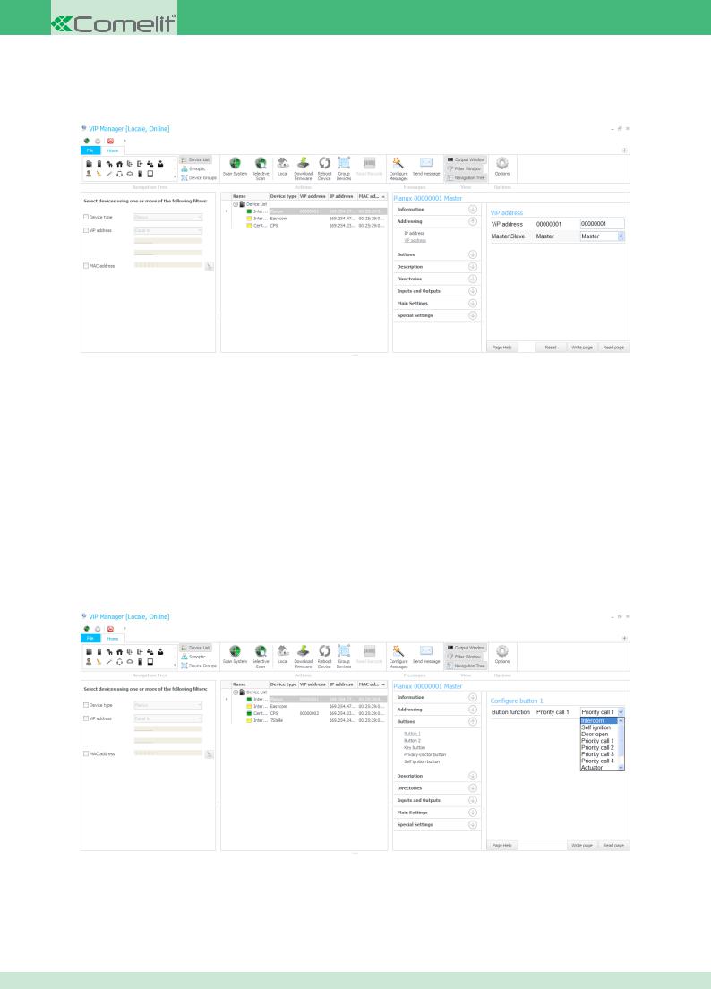
4.4.3 Programming buttons
ALL DEVICES
The buttons on ViP internal units can be programmed for various functions depending on the product.
The procedure for accessing the button programming menu on all internal units is described below.
1.Select the internal unit by clicking on the navigation tree
2.Expand the “Buttons” menu
3.Select the button you wish to program
4.Use the drop-down menu in the “Button function” box to select the function you wish to assign to the button
5.Depending on the selected function, follow the configuration procedure illustrated in the next few pages of this manual
6. Click “Write page” to apply the settings
CONTENTS
14
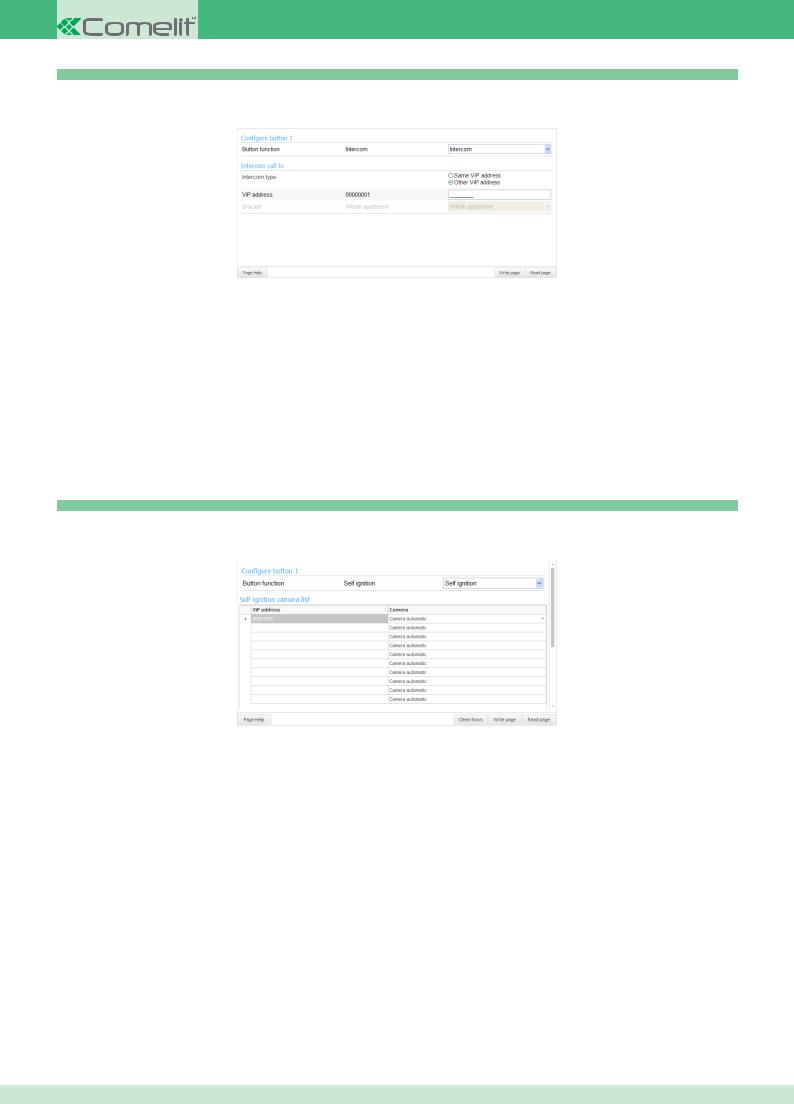
4.4.3.1 Intercom function
ALL DEVICES
This function is used to send an intercom call to a specific device.
◊Intercom type: this box offers two options
•Same ViP address: if this option is selected, when the button is pressed an intercom call is sent to a device with the same ViP address. This
device should be selected from the “Bracket” drop-down menu
• Other ViP address: if this option is selected, when the button is pressed an intercom call is sent to a device with a different ViP address. This device should be indicated by entering the address in the “ViP address” box. In this case it is not possible to select a master or a slave; only the whole apartment can be called
◊ ViP address: box used to enter the ViP address of the device you wish to associate with the intercom call if the option “Other ViP address”has been selected
◊ Bracket: drop-down menu used to select the ViP address of the device you wish to associate with the intercom call if the option “Same ViP address” has been selected
4.4.3.2 Self ignition function
PLANUX - 7 STELLE - MAESTRO - smart
This function is used to display the images transmitted by the camera of one or more devices connected to the system.
◊ViP address: box used to enter the ViP address of the device you wish to associate with the self ignition function
◊Camera: drop-down menu used to select which device camera you wish to display.
The “Camera automatic” is always the first on the device:
•Camera automatic on External Unit device is its camera.
•Camera automatic on device 1445 is always CAMERA 1.
N.B. Several devices or several cameras belonging to the same device can be linked. In this case, every time the button programmed with the self ignition function is pressed, the images transmitted by the various devices are displayed cyclically.
 The self ignition function must also be enabled on the external unit
CONTENTS
15
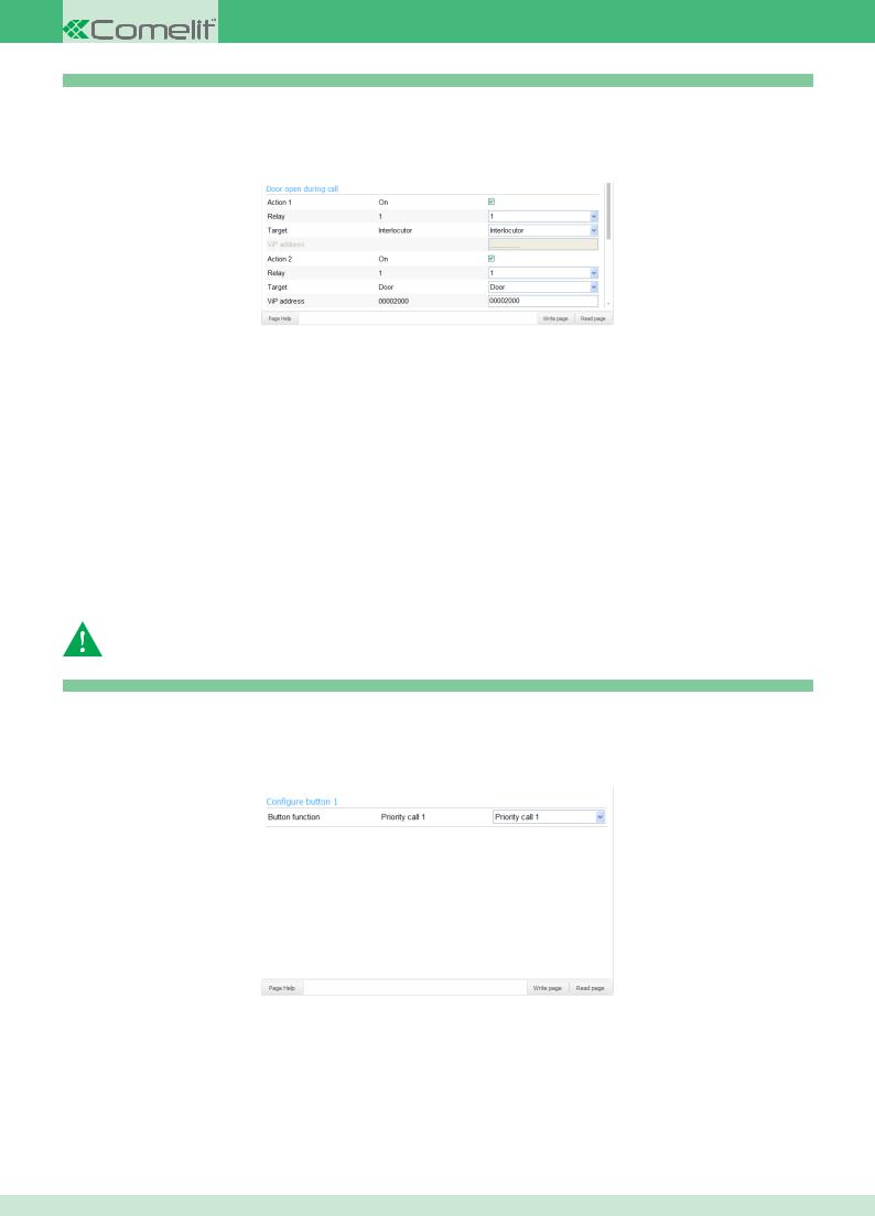
4.4.3.3 Open door function
ALL DEVICES
This function has two statuses:
◊Door open during call: one or two actions will be carried out when a call with the external unit is in progress
◊Door open during rest time: one or two actions will be carried out when no calls are in progress
Up to 2 actions can be carried out at the same time for each operating status
•Action 1 / 2:if this box is ticked, the action will be activated
•Relay: drop-down menu used to select whether to activate relay 1 or 2
•Destination: drop-down menu used to select whether to activate the relay for the external unit making the call or for another module connected to the system. If you select the second option you will need to fill in the “ViP address” box to indicate the module with which you wish to interact
•ViP address: box used to enter the address of the module if the “Door” option has been selected in the previous box
For example, the screen illustrated above should be read as follows:
Action 1 Activates relay number 1 of the interlocutor (the external unit making the call)
Action 2 Activates relay number 1 of the Door with ViP address 00002000
The same applies for the function in “Door open during rest time” status, except that in this case you will not have theInterlocutor option but will still have to enter the ViP address of the module with which you wish to interact.
The external unit relays must also be configured to activate with the Open door function
The external units must also be configured to activate in no call mode, by activating the functionAccept open door when idle
4.4.3.4 Priority Call 1 / 2 / 3 / 4 function
ALL DEVICES
Priority calls take precedence over floor door calls, user calls from the external unit, switchboard calls and intercom calls. Usually they are used for calls indicating Alarm, Panic, Fire etc.
Press the button programmed for this function to send a call to the set device, usually a porter switchboard. For call configuration, refer to theSet alarm procedure
CONTENTS
16
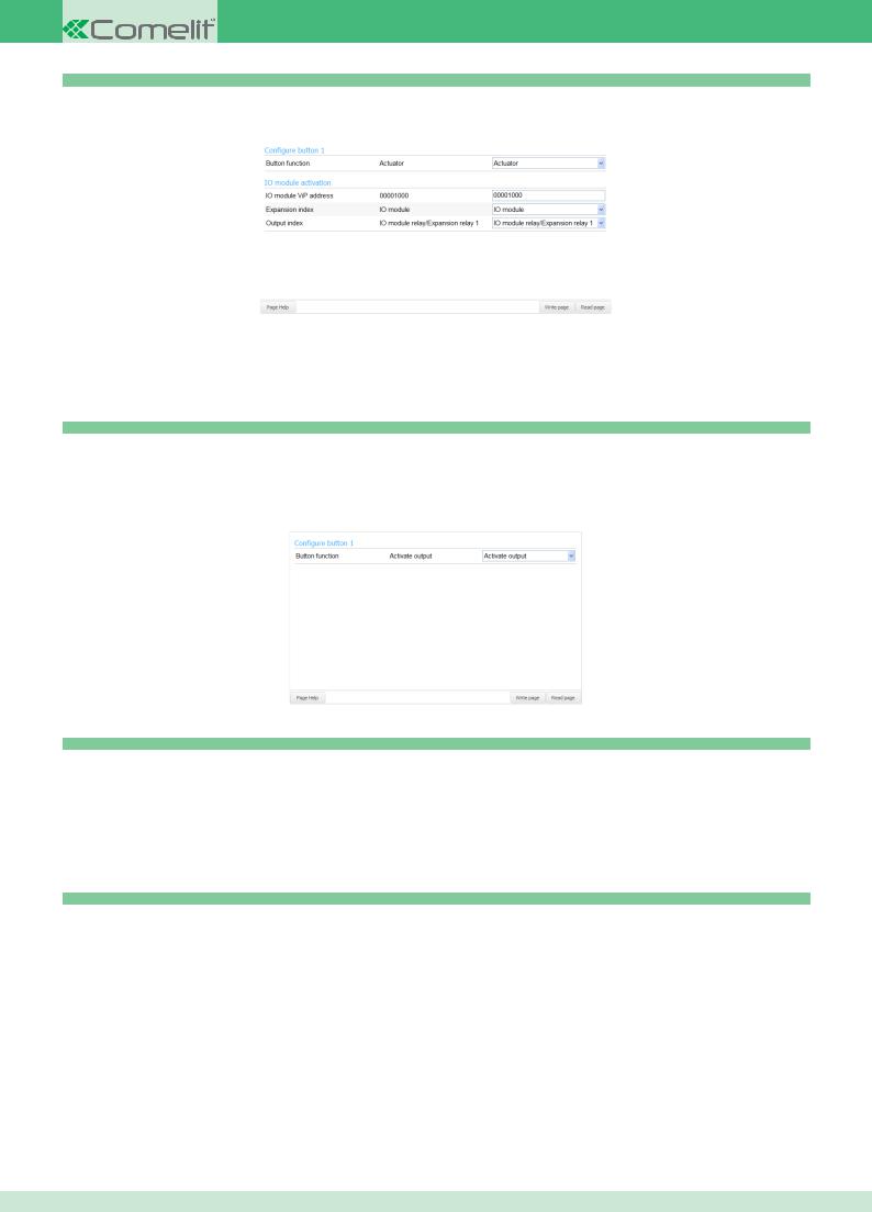
4.4.3.5 Actuator function
ALL DEVICES
This function is used to activate the relay output of an IO actuator module or that of an expansion device connected to it.
◊IO module ViP address: box used to enter the ViP address of the IO module you wish to control
◊Expansion index: drop-down menu used to choose whether you wish to interact directly with the IO module indicated above, or with an
expansion module connected to it
◊ Output index: drop-down menu used to select the specific output you wish to control
4.4.3.6 Activate output function
PLANUX - 7 Stelle - Maestro - smart
This function is used to enable the NC/NO output for the internal unit by pressing the button
 The output must be configured in line with the NC/NO output configurationprocedure
4.4.3.7 Privacy / Doctor / Doctor and Privacy function planux - 7 stelle - maestro - easycom
◊Privacy: Privacy mode means muting of the ringtone on receipt of a call from the external unit, switchboard and internal unit
◊Doctor: the Doctor function enables automatic activation of the lock-release in response to a call from the external unit
◊Doctor and Privacy: the Doctor and Privacy function, as well as disabling the internal unit ringtone in the same way as the Privacy function, also
enables automatic activation of the lock-release in response to a call from the external unit
4.4.3.8 Disabled function
ALL DEVICES
This function is used to disable the button.
CONTENTS
17
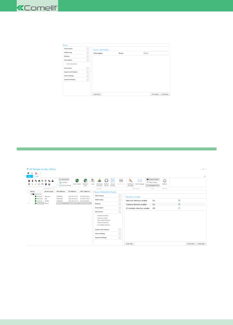
4.4.4 Assigning / Editing the Device description
ALL DEVICES
The description is used to identify devices more easily in complex systems. Once a description has been set, it can be viewed in theNavigation Tree window, in the “Name” column.
1.Select the internal unit by clicking on the navigation tree
2.Expand the “Description” menu
3.Select the “Device description” menu
4.Fill in the box on the right-hand side
5.Click “Write page” to apply the settings
4.4.5 Directory management
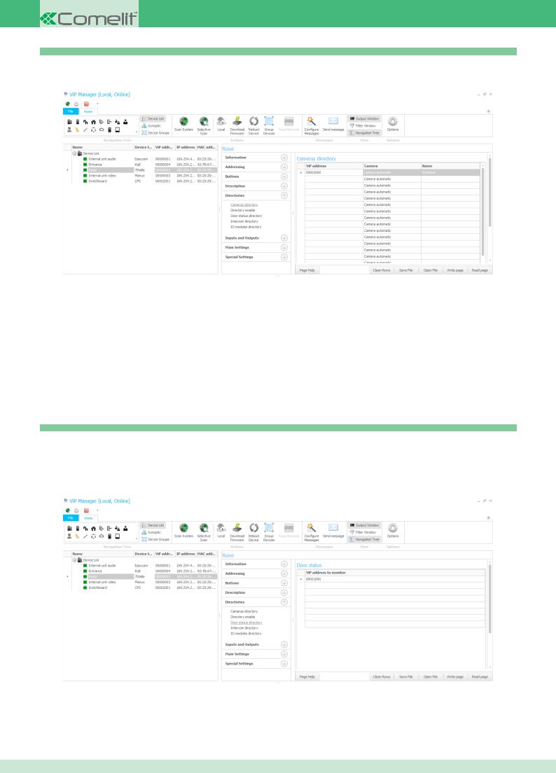
4.4.5.1 Directory enable
planux - 7 stelle - maestro - smart
In order to view and use the directories from the internal unit menu, you must enable them from the ViP Manager.
1.Select the internal unit by clicking on the navigation tree
2.Expand the “Directories” menu
3.Select the “Directory enable” menu
4.Tick the box you to the right of the entry you wish to enable
5.Click “Write page” to apply the settings
CONTENTS
18
4.4.5.2 Cameras directory
planux - 7 stelle - maestro - smart
The procedure used to compile the camera directory is described below.
1.Select the internal unit by clicking on the navigation tree
2.Expand the “Directories” menu
3.Select the “Cameras directory” menu
◊ViP address: box used to enter the ViP address of the camera module
◊Camera: drop-down menu used to select which device camera you wish to display.
The “Camera automatic” is always the first on the device:
•Camera automatic on External Unit device is its camera.
•Camera automatic on device 1445 is always CAMERA 1.
◊Name: name that will be displayed in the camera directory on the internal unit
4. Click “Write page” to apply the settings
4.4.5.3 Door status directory all devices
The door status directory is used to create a list of external units to be monitored.
 This function requires the monitored external units to have at least one input set with the Door status function
1.Select the internal unit by clicking on the navigation tree
2.Expand the “Directories” menu
3.Select the “Door status directory” menu
◊ ViP address to monitor: box used to enter the ViP address of the external unit you wish to monitor
4. Click “Write page” to apply the settings
CONTENTS
19

4.4.5.4 Intercom directory
planux - 7 stelle - maestro - smart
The procedure used to compile the intercom directory is described below.
1.Select the internal unit by clicking on the navigation tree
2.Expand the “Directories” menu
3.Select the “Intercom directory” menu
◊ViP address: box used to enter the ViP address of the user you wish to call
◊Master / Slave: drop-down menu used to select whether you wish to call the master or slave device associated with the ViP address entered in
the previous step
◊ Name: name that will be displayed in the intercom directory on the internal unit
4. Click “Write page” to apply the settings
4.4.5.5 IO modules directory
planux - 7 stelle - maestro - smart
The procedure used to compile the IO modules directory is described below.
1.Select the internal unit by clicking on the navigation tree
2.Expand the “Directories” menu
3.Select the “IO modules directory” menu
◊IO module ViP address: box used to enter the ViP address of the IO module with which you wish to interact
◊Expansion index: drop-down menu used to select whether you wish to interact directly with the IO module, or with an expansion module
connected to it
◊Output index: drop-down menu used to select the output you wish to control
◊Name: name that will be displayed in the IO modules directory on the internal unit
4. Click “Write page” to apply the settings
CONTENTS
20
4.4.6 Input and output management
4.4.6.1 NC/NO output configuration
planux - 7 stelle - maestro - smart
The monitors in the ViP series (Planux, 7Stelle, Maestro and Smart) are equipped with a NC/NO output which can be programmed as monostable or bistable. This output can be controlled by one of the buttons on board the monitor, or by one of the inputs if suitably configured using theActivate output function.
1. |
Select the internal unit by clicking on the navigation tree |
2. |
Expand the “Inputs and Outputs” menu |
3. |
Select the “Output” menu |
◊ |
Output function: drop-down menu used to choose whether the output will be Monostable or Bistable |
◊ |
Polarity: drop-down menu used to choose whether the initial output status will be NC (normally closed) or NO (normally open) |
◊ |
Duration: drop-down menu used to select the closing / opening duration of the output if the function is set to Monostable |
4. |
Click “Write page” to apply the settings |
4.4.6.2 Activate output upon call
planux - 7 stelle - maestro - smart
The NC/NO output or an IO module can be enabled automatically on receipt of a call.
1.Select the internal unit by clicking on the navigation tree
2.Expand the “Inputs and Outputs” menu
3.Select the “Activate output upon call” menu
CONTENTS
21
For each type of call on the list, you can choose whether to activate the NC/NO output or an IO module using the drop-down menu in the “Activation function” column.
If you select an IO module, you will also need to fill in the boxes:
◊IO module ViP address: box used to enter the ViP address you wish to associate with the function
◊Expansion index: drop-down menu used to select whether you wish to interact directly with the IO module, or with an expansion module
connected to it
◊ Output index: drop-down menu used to select the output you wish to control
4. Click “Write page” to apply the settings
4.4.6.3 Input configuration all devices
Every internal unit is equipped with at least 2 NC/NO inputs which can be programmed with the following functions:
◊Open door: to use this function the parameters must be configured in the Open door function for the key button
◊cfp: Floor door call function
◊Burglar alarm: sends an alarm call to the recipient selected in the Alarms menu. To set this function, see the Burglar menu
◊Priority Call 1 / 2 / 3 / 4
◊Actuator
◊Activate output
4.4.7 Main settings
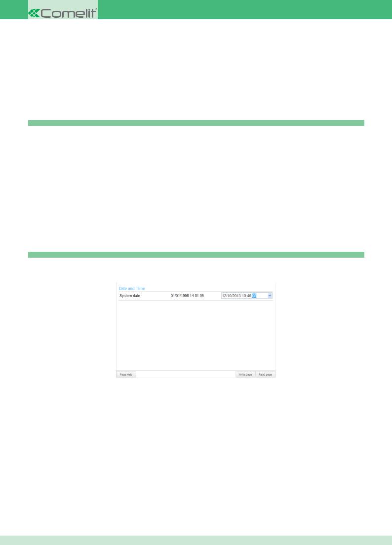
4.4.7.1 Setting the date and time
planux - 7 stelle - maestro - smart
The system date and time can be changed on some internal units.
1.Select the internal unit by clicking on the navigation tree
2.Expand the “Main Settings” menu
3.Select the “Date and Time” menu
4.Change the date and time using the box on the right-hand side
5.Click “Write page” to apply the settings
CONTENTS
22
Loading...