Comelit IX0101KP User Manual
EN
TECHNICAL
MANUAL
VANDAL RESISTANT DIGITAL ACCESS CONTROL KEYPAD |
|
|
Programming & Installation |
|
Passion.Technology. Design. |
Complete Manual |
|
|
|
|
|
|
|
|

TABLE OF CONTENTS
INTRODUCTION ······························································································································· |
3 |
|
ASSEMBLY ········································································································································ |
3 |
|
DESCRIPTION OF CONNECTION TERMINALS & INDICATORS ······················································ |
4-6 |
|
Connec on Terminals················································································································· |
4-6 |
|
The LED Indicators ························································································································· |
7 |
|
Back Ligh ng·································································································································· |
7 |
|
The Pacifier Tones & The LED Indica ng Signals ··········································································· |
7 |
|
STANDARD PROGRAMMING SUMMARY CHART·········································································· 8-10 SETTING & PROGRAMMING······································································································ 11-26 Criteria for Programming ············································································································· 11 Enter and Exiy Programming Mode ····························································································· 11
The DAP Jumper (Direct Access to Programming Mode) – If Master Code is Forgo en ············· 11
Programming A New Master Code ······························································································ 12 System Refresh (Complete Data Refresh) ··················································································· 12 ProgrammingTheUserCodes ······································································································· 13 Programming The Super User Code ························································································ 14-15 Programming The Duress Codes ·································································································· 16 Programming The Visitor Codes ··································································································· 17 Dele ng User Codes & Other Func on Codes·············································································· 18 Configura on of Output Modes for Outputs 1 & 2 ································································· 19-20 False A empt System Lock-up or Repor ng ················································································ 21 Door Forced-Open Warning & Alarm ··························································································· 22 Output Ac va on Announcer ······································································································ 22 User Code Entry Modes (Auto or Manual) ··················································································· 23 Pacifier Tones ON-OFF·················································································································· 23 Main Status LED Flashing ON-OFF ································································································ 23 Egress Delay & Warning ·········································································································· 24-25 Delay Time to Start Door-Propped-Up Warning ·········································································· 25
SET KEYPAD TO SINGLE USER MODE (to whom it may require) ············································· 26-27
Programming Summary Chart for “Single-User Mode”··························································· 26-27 Programming Examples for “Single-User Mode”·········································································· 27 SPECIFICATIONS ······························································································································ 28 APPLICATION EXAMPLE ············································································································ 29-31 APPLICATION HINTS FOR THE AUXILIARY FACILITIES ······························································ 32-34 AUXILIARY INFORMATION ············································································································· 35
2

INTRODUCTION
Dual relay output, vandal resistant weatherproof keypads. They employ durable back-lit metal bu on keyboard and rugged metal housing ideally for high tra c and harsh environment applica ons.
The Output 1 is a Form C relay with 5 Amp contact ra ng mainly designed for electric door lock actua on. The Output 2 is a Form C relay with 1 Amp ra ng.
3
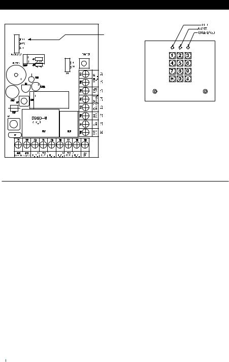
DESCRIPTION OF CONNECTION TERMINALS & INDICATORS
|
|
|
|
|
|
|
|
BACK-LIT JUMPER |
1 |
2 |
3 |
4 |
5 |
6 |
7 |
8 |
9 |
CONNECTION TERMINALS
● 1 - 2 : 12-24V AC/DC -- POWER INPUT
Connectto12-24VACorDCpowersupply.The(–)supply,Terminal(2)and(–)GNDTerminal(12) are the common grounding points of the keypad system. No selec on jumper is required for the fullinputvoltagerange.ConnectDCpowerwiththe(+)and(–)polarityindicated;andthereisno polarity discrimina on for AC power input.
● 3 - 4 - 5 : OUTPUT 1 -- DOOR LOCK
Output 1 is a relay controlled by the group 1 user codes. It consists of Normally Open (N.O.) and Normally Closed (N.C.) dry contacts of 5 Amp maximum ra ng for electric door lock actua on. Use N.O. contact for Fail-secure electric lock while N.C. contact for Fail-safe.
The output contact is programmable for Start / Stop (toggle) mode or mer mode from 1 to 999 seconds. See programming Loca on 40-43 for the details.
● 6 - 7 - 8 : OUTPUT 2
This is an auxiliary relay output with 1 Amp ra ng Normally Open (N.0.) and Normally Closed (N.C.) dry contacts controlled by the group 2 user codes, which is ideal for controlling security systems&automa coperators.ItisprogrammableforStart/Stop(toggle)opera onor ming opera on from 1 to 999 seconds.
See programming Loca on 5053 for the details.
4

● 9 - EG IN -- EGRESS INPUT
A Normally Open (N.O.) input terminal refers to (–) ground, with the help of a normally open bu on to ac vate the Output 1 for the same me period as like the user code. Egress bu on is usually put inside the house near the door.
More than one egress bu ons can be connected in parallel to the terminal. Leave this terminal open if it is not used.
● 10 : KEY ACT -- KEYPAD ACTIVE OUTPUT
This is an NPN transistor open collector output with maximum ra ngs of 100mA sink and 24V DC.
It switches to (–) ground for 10 seconds on each key touching This can be used to turn on lights,
CCTV camera, or buzzer to no fy a guard. See Applica on Hints for more informa on.
● 11 : DU OUT -- DURESS OUTPUT
An NPN transistor open collector output. It switches to (–) ground a er the Duress Code is entered. Use it to trigger an alarm zone, an auto-dialer or turn on a buzzer to no fy a guard. Ic max: 100mA sink. Vc max: 24VDC.
● 12 : GND (-) -- COMMON GROUND
An auxiliary nega ve common ground of the keypad.
● 13 : DOOR SENS -- DOOR POSITION SENSOR INPUT
A Normally Closed (N.C.) input terminal referring to (–) ground. With the help of a normally closedmagne cdoorswitch,thesystemmonitorstheposi onofopenorclosedofthedoorand will give the following func ons:
NOTE: Always connect this terminal to (–) ground if not used.
1)Door Auto Re-lock
Thesystemwillimmediatelyrelockthedoora ervalid accesshasbeengainedbeforetheend of the programmed me for output 1, that prevents unwanted "tailgate" entries.
2)Door Forced Open Warning
The keypad will generate door forced-open warning instantly if the door is forced to open withoutavalidcodeuserentryoregressinput.Thewarningwilllastfor60secondsandcanbe stopped any me with an user code for output 1. This func on is selectable via the programming op ons at Loca on 80.
3)Door Propped-up Warning
When the door is le open longer than the allowable me. The keypad will generate door propped-up warning a er the expiry of the pre-set door-open- me un l the door is closed again. The door-open- me is programmable from 1 to 999 seconds at Loca on 9.
4)Inter-lock Control
Theinter-lockcontroloutputgoesto(–)whilethedoorisopeninordertogivesignaltodisable the other keypad in the inter-lock system.
5

● 14 : O/P 1 INHIB. -- OUTPUT 1 INHIBIT
A Normally Open (N.O.) input terminal refers to (–) ground. Both user code 1 and Egress bu on can not ac vate output 1 while this terminal is ed to (–) ground. It is prepared for cross wire connec on in Inter-lock applica on.
● 15 : INT. LOCK -- INTER-LOCK CONTROL OUTPUT
An NPN transistor open collector output. It is OFF at normal condi on and switches to (–) ground immediately for the first 5 seconds a er keying in a valid user code or pressing the egress bu on to operateoutput1,then,itwillkeeptyingto(–)groundduringthe methatthedoorposi onsensor is open circuit due to door opening. Use this output to control the other keypad in an inter-lock system to prevent that both doors can be opened at the same me.
An inter-lock system is a two-door system that always allows only one door to open during the opera on me.
Whileoneofthedoorsinthesystemisopened,theotherdoorkeepscloseun ltheopeneddooris re-closed in order to prevent the unauthorized people dashing into a protected area.
● 16 - 17 : TAMPER N.C.
NormallyClosedcontactwhilethekeypadissecuredonthebox.Itisopenwhilekeypadisseparated from the box. Connect this N.C. terminal to a 24 hour zone of an alarm system if necessary.
6

THE LED INDICATORS
● MAINS (AMBER)
This is a status indicator. It flashes during standby and other indica ons in synchroniza on with the pacifier tones. See the chart of LED indica on signals below for the details.
● DOOR (GREEN & RED)
This is a dual LED. It lights up in green while output 1 is ac ve (The door is open) and red while Output 1 is Inhibited; including manually inhibited with Super User Code or due to False Code Lock-up se ng in Loca on 70.
● Auxiliary (RED)
It lights up while output 2 is ac ve.
BACK LIGHTING (BACK-LIT JUMPER SELECTION)
1.FULL BACKLIT ---- The keypad gives dim backlit in standby. It turns to full backlit when a key bu on is pressed, then back to dim backlit 10 seconds a er the last key bu on is pressed.
2.AUTO BACKLIT ---- The keypad gives no backlit in standby. It turns to full backlit automa cally when a key bu on is pressed, then back to OFF 10 seconds a er the last key bu on is pressed.
3.BACKLIT OFF ----- The keypad gives no backlit at all.
THE PACIFIER TONES & THE LED INDICATING SIGNALS
The built-in buzzer and the MAINS LED indicator give the following tones and signals for opera on status:
|
STATUS |
|
TONES* |
|
LED SIGNALS |
1. In programming mode |
--- |
ON |
|||
2. |
Successful key entry |
1 |
Beep |
1 |
Flash |
3. |
Successful code entry |
2 |
Beeps |
2 |
Flashes |
4. |
Unsuccessful code entry |
5 |
Beeps |
5 |
Flashes |
5. |
DAP jumper not replaced |
Continuous Beeps |
Continuous Flashes |
||
6. |
In standby mode |
--- |
1 |
Flash in 2 seconds interval |
|
7. Output relay activated |
1 second Long Beep ** |
--- |
|||
NOTE:
* All Pacifier Tones can be enabled or disabled through programming op ons at Loca on 83.
** The Output Ac va on Beep can be enabled or disabled through programming op ons at Loca on 81.
7

STANDARD PROGRAMMING SUMMARY CHART
A) Enter Programming Mode with Master Code |
(Exit-Factory Master Code: 0 0 0 0) |
||
Entry of Master Code |
Confirm |
Comments |
|
|
|
Set system to Programming Mode |
|
NOTE: Factory has put a master code into the keypad before exit-factory, owner may take it for first me use.
B) System Refreshing – Installer Programming |
(Default: 8 9 0 1, Mul -user mode) |
||
Refresh Code |
Confirm |
Comments |
|
|
|
Clearallpreviouslystoreddataandsetkeypadbacktodefaultvaluesexcept |
|
|
|
Master Code |
|
C) Code Entries – User Programming |
|
|
|
|
1) Recording Master Code and User Codes – User Programming |
(No Default Codes) |
|||
Loca ons |
User IDs Entry of Codes |
Confirm |
Comments |
|
|
4 to 8 digits |
|
Owner’s Master Code for se ng system to |
|
|
|
|
programming mode |
|
00 to 99 |
4 to 8 digits |
0 to 9 |
4 to 8 digits |
100 User Codes for opera ng Output 1
10 User Codes for opera ng Output 2
2) Recording Super User Code – User Programming |
|
(No Default Codes) |
||||||
Loca on |
Entry of Code |
Confirm |
Comments |
|
|
|
||
|
4 to 8 digits |
|
Owner’s Mul -task User Code |
|||||
|
|
|
|
|||||
3) Recording Duress Codes – User Programming |
|
(No Default Codes) |
||||||
Loca on |
User IDs |
Entry of Code |
Confirm |
Comments |
|
|
||
|
0 to 9 |
4 to 8 digits |
|
10 emergency user codes for actua ng Output 1 and |
||||
|
|
|
|
|
Duress Output simultaneously to report user under |
|||
|
|
|
|
|
duress |
|
|
|
|
|
|
||||||
4) Recording the Visitor Codes – User Programming |
(No Default Codes) |
|||||||
Loca on |
User IDs |
Opera onTime |
Entry of Code |
Confirm |
Comments |
|||
|
0 to 9 |
00 to 99 |
4 to 8 digits |
|
10 visitor codes for opera ng Output 1. |
|||
Opera on Time:
00 = One me use only
01 to 99 = Valid within me limit of 1-99 hours
8
D) Configura onof OutputModes –Installer Programming (Default: Momentary, 1-second for all 3 outputs)
Loca on Code of Timing
|
1 to 999 |
|
|
|
|
|
|
Loca on Code of Timing |
|
|
1 to 999 |
|
|
Confirm Comments
Output 1, Momentary Mode from 1 to 999 seconds(default=1 second)
Output1,Start / StopMode(toggle)
Output1,Start / StopMode(toggle)with2-digit Acceleratedstart code
Output1,Start / StopMode(toggle)with3-digit Acceleratedstart code
Confirm Comments
Output 2, Momentary Mode from 1 to 999 seconds (default = 1 second
Output 2, Start / Stop Mode (toggle)
Output 2, Start / Stop Mode (toggle) with 2-digit Accelerated Start Code
Output 2, Start / Stop Mode (toggle) with 3-digit Accelerated Start Code
E) False Code Lock-up & Repor ng – Installer Programming |
(Default: 10 tries / 30 seconds) |
Loca on Lock-up Modes Confirm Comments
1 |
10 successive false codes, keypad locks during 30 seconds (default) |
||
2 |
10 successive false codes, Duress Output actuates (switches to GND |
||
5 to 10 |
Selectable of 5 to 10 false code, keypad locks during 15 minutes. |
||
|
Locking can be released at any me with |
|
|
|
Super User Code |
||
00 |
Disappearance of all the above securi es |
||
F) Door Forced-Open Alarm – Installer Programming |
(Default: Disabled) |
|||
Loca on |
Func on Codes |
Confirm |
Comments |
|
|
|
|
Door Forced-Open Warning disabled (default) |
|
|
|
|
Door Forced-Open Warning enabled, ac ve me is 60 seconds |
|
|
|
|||
G) Output Ac va on (Door Open) Announcer – Installer Programming |
(Default: 1 long beep) |
|||
Loca on |
Func on Codes |
Confirm |
Comments |
|
|
|
|
|
|
|
No no fica on.
2 short-beep is given when the door lock is opened.
1 second long beep no fica on is given when the door lock is opened. It is good for locking device give no sound when it ac vates. Such as a magne c lock (default)
9

H) User Code Entry Modes (Auto or Manual) – Installer Programming |
(Default: Manual) |
|||
Loca on |
Func on Codes |
Confirm |
Comments |
|
|
|
|
Manual Entry Mode requires to enter bu on a er the user |
|
|
|
|
codes. It is NOT necessary to set the Master Code and all User |
|
|
|
|
Codes in the same digit length. They can be 4-8 digits mixed |
|
|
|
|
arbitrary (default) |
|
|
|
|
Auto Entry Mode does not need to enter bu on a er the user |
|
|
|
|
codes. However, All the User Codes MUST be in the same digit |
|
|
|
|
length of the Master Code and they can be 4-8 digits |
|
|
|
|||
I) Pacifier Tones (Key-press beeps) – Installer Programming |
(Default: ON) |
|||
Loca on |
Func on Codes |
Confirm |
Comments |
|
|
|
|
|
|
|
Pacifier tone OFF, good for silent environment
Pacifier tone ON for every key-press (default)
J) Main LED Flashing ON-OFF – Installer Programming |
(Default: Flashing) |
Loca on Func on Codes Confirm Comments
Main LED OFF during system standby, good for people do not like flashing LED at night
Main LED flashing during system standby (default)
K) Egress Delay & Warning – Installer Programming |
(Default: Instant, No warning) |
|||||
Loca on |
Delay Op ons |
Confirm |
Comments |
|
|
|
|
0 to 4 |
|
Five delay op ons for opera ng Output 1 with egress bu on: |
|||
|
|
|
0 |
– Instant ac va on, no delay and warning (default) |
||
|
|
|
1 |
– Momentary contact, 5 seconds delay with warning |
||
|
|
|
2 |
– Momentary contact, 10 seconds delay with warning |
||
|
|
|
3 |
– Hold contact, 5 seconds delay with warning |
|
|
|
|
|
4 |
– Hold contact, 10 seconds delay with warning |
|
|
|
|
|||||
L) Delay Time to Start Door Propped-up Warning – Installer Programming |
(Default: OFF) |
|||||
Loca on |
Delay Time |
Confirm |
|
Comments |
|
|
0
1 to 999
No propped-up Warning (default)
Delay me from 1 to 999 seconds before door propped-up Warning starts.while the door is stuck and le open
M) Exit Programming Mode
Confirm Comments
It is always necessary to set keypad back to normal opera ons a er programming
10
SETTING & PROGRAMMING
Criteria for Programming
(1)The keypad MUST be in Programming Mode for making Se ng and Data Changes.
(2)Programming can be accomplished in workshop or at the installa on site. All data are stored in a non-vola le memory and will not be lost in power o .
(3)DO NOT disconnect the keypad from power while in programming mode; otherwise could cause a keypad memory error.
Enter and Exit Programming Mode
It is necessary to set the keypad in programming mode with the Master Code for all programming.
1.Enter programming mode with the master code and confirm it with key.
For the owner’s convenience in programming at the first me, a Master Code has been set before exit-factory.
Master Code |
Confirm |
--- Keypad is now in programming mode
2.Use the programming instruc ons stated in “Programming Summary Chart” to make change of the keypad data. Programming can be done con nuously one by one on the Loca ons required un l finish.
3.Exit the programming mode by pressing the key a er all the required programming isfinished.
NOTE:
●For security reason, owner should program a new master code to replace the exit-factory master code.
●Once a new master code is programmed, the old master code is replaced.
●Use DAP jumper to set keypad to programming mode if master code is forgo en. See DAP Jumper descrip on for the details.
The DAP Jumper (Direct Access to Programming Mode) – If Master Code is Forgo en
If the master code is forgo en, use the DAP jumper (located on the main circuit board) to override
the forgo en code and permit the keypad direct entry into programming mode. Apply the procedures precisely as follows.
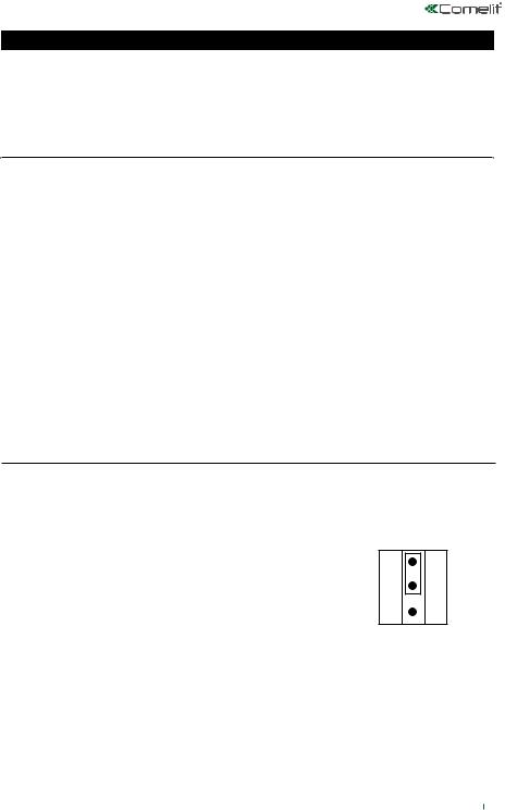
2.Move the DAP jumper from OFF to ON. OFF DAP
3.Reconnect the power supply. ON The keypad will start beeping.
4.Move the DAP jumper back to OFF posi on.
The keypad will stop beeping as soon as the jumper is removed.
5.The keypad is now in the programming mode, ready to receive new programming data.
6.Re-program the keypad with the available op ons shown on the “Programming Summary Chart”.1. Disconnect the power supply.
●The opera on of DAP jumper is for se ng the keypad into programming mode only. It does not a ect the stored data in the programming loca ons.
●A er the keypad is in programming mode,a new master code may be programmed to replace the one that was forgo en.
11
 Loading...