


EN
QUICK
REFERENCE
GUIDE
Quick reference Guide for
Single-User Kit HFX-9000M
EN |
FR |
ES |
also available in French and Spanish
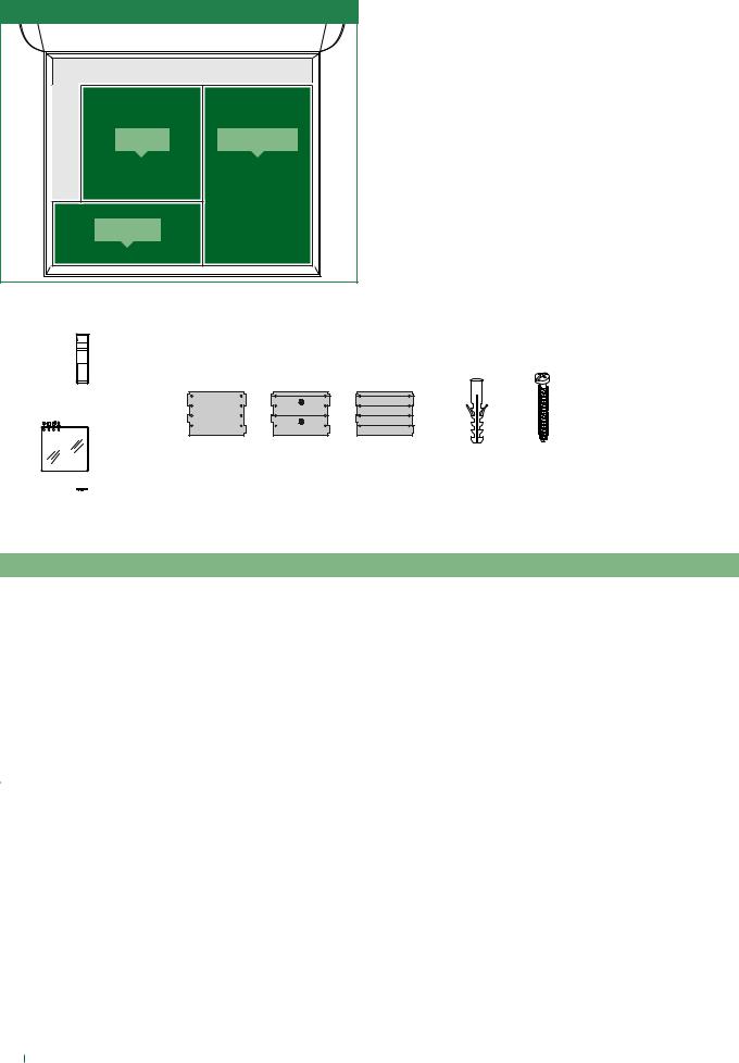
1. Contents of the package
HFX-9000M Kit
1209/8 |
EX-9000H |
EX-DSM |
|
1209/8 - BUS Power supply
×1 ×4
power supply |
screws |
EX-DSM - External unit
×1 |
×1 |
×1 |
×1 |
×3 |
×3 |
PUSH HERE
Replaceable nameplates
external unit |
|
|
|
for 1 user |
for 2 users |
for 4 users |
dry wall anchors |
tech sheet |
EX-9000H - Monitor
|
|
×1 |
monitor wall |
×1 |
×4 |
×4 |
|
|
|
|
|
|
|||
|
|
|
|
|
|
||
|
|
|
support |
|
dry wall |
screws |
|
|
|
|
|
|
|
anchors |
|
|
×1 |
|
metal frame |
×1 |
|
×4 |
|
|
|
|
|
|
|||
|
|
|
|
|
|
||
monitor + terminal block |
|
support |
|
screws |
|||
|
|
|
|
|
|
|
|
|
|
|
|
|
Technical Manual |
|
|
|
|
|
|
|
EN |
|
|
|
|
|
|
|
QUICK |
|
|
|
×4 |
|
|
|
REFERENCE |
|
|
|
|
|
|
GUIDE |
|
|
|
|
|
×2 |
|
|
|
|
|
×2 |
|
|
|
|
|
|
|
|
×4 |
|
|
|
|
|
|
clips for dry |
screws |
|
|
|
Single-User Kit HFX-9000M |
|
|
lined walls |
|
|
tech sheet |
|
Quick reference Guide for |
|
|
|
|
|
EN FR ES |
|
|
||
|
|
|
|
|
also available in |
|
|
|
|
|
|
|
French and Spanish |
|
|
|
|
|
|
|
|
|
|
2
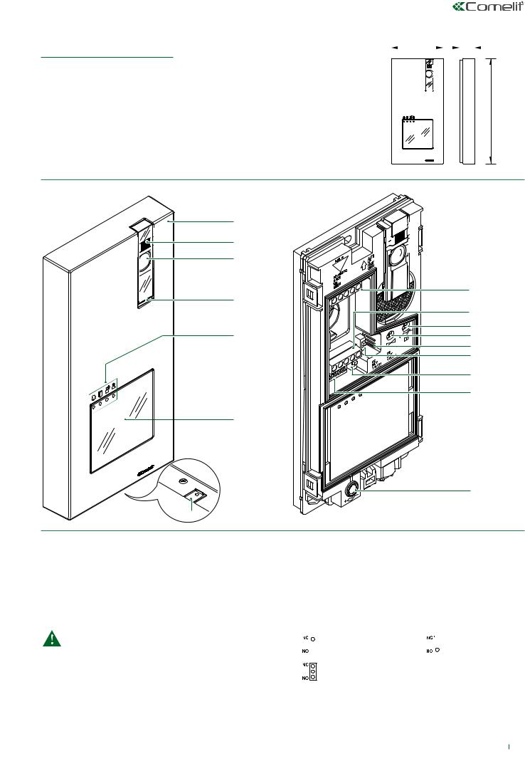
2. Parts identification
2.1 EX-DSM EXTERNAL UNIT
|
3.79 in |
|
|
|
|
|
|
|
|
1.06 |
|
in |
|
|
|
|
|
|
|
|
|||||
|
|
|
|
|
|
|
|
|
|
|
|
|
|
|
|
|
|
|
|
|
|
|
|
|
|
|
|
|
|
|
|
|
|
|
|
|
|
|
|
|
|
|
|
|
|
|
|
|
|
|
|
|
|
|
|
|
|
|
|
|
|
|
|
|
|
|
|
|
|
|
|
|
|
|
|
|
|
|
|
|
|
|
|
|
|
|
|
|
|
|
7.72 in
1.
2.
3.
4.
5.
6.
7. |
8. |
9. |
10. |
11. |
12. |
13. |
14. |
15. |
16. |
1.Die-cast aluminium cover
2.Camera lighting LED
3.Wide-angle color camera
4.Loudspeaker
5.Indicator LED:
 call sent /
  lock-release enabled
 audio enabled /
  system engaged
6.Transparent label-holder front panel
For instructions on replacing the nameplate, see the complete manual.
For instructions on enabling the buttons on 2/4 button front panels, see the “special functions programming” section on the complete manual.
7.Microphone
8.Terminal block M1
LL bus line connection
RTE timed local lock-release input
COM common input for RTE and DO contacts
DO door open indication input
9.Terminal block M2
SEconnection for electric door lock SE+ connection for electric door lock NC relay normally closed contact NO relay normally open contact
C relay common contact
10.Loudspeaker volume control
11.Audio balance
12.JP1 enable RC network for door lock filter on relay contacts
|
ON CONTACTS C. NO. |
|
ON CONTACTS C. NC. |
|
|||
|
|
|
|
DISABLED: CLEAN CONTACT
13.CNF programming confirmation switch
14.PR programming input/output switch
15.S1 DIP SWITCH for function programming
16.Microphone volume control
3
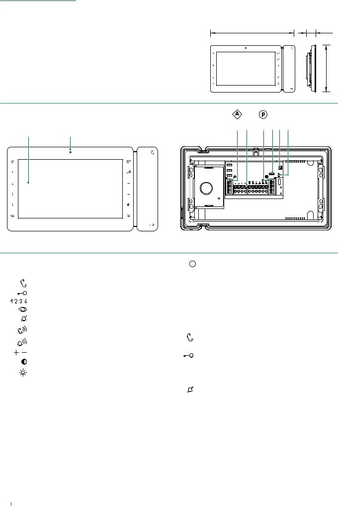
2.2 EX-9000H MONITOR
8.77 in |
0.98 in |
|
4.88 in |
1 |
2 |
3 |
4 |
5 |
6 |
7 |
8 |
1.7” colour LCD screen
2.Microphone
Audio key / Paging call key
Lock-release key
Keys 1-2-3-4 (programmable)
Self-ignition key (programmable)
Privacy key
Audio volume key
Ringtone volume key
Value 'Up/Down' key
Contrast key
Brightness key
3.S1  Micro-switches for user code setting
4.Terminal block for system connection:
L L Bus line connection terminals - + Power supply terminals
IN2 IN1 Input terminals (programmable)
S- S+ Terminals for additional ringtone output CFP2 CFP1 Outside door call input
5. S2  Micro-switches for programming keys and functions DIP 1-2-3-4 for key function programming
DIP 5-6 access to programming DIP 7 unused
DIP 8: leave default setting (OFF)
6.CV6 see the full manual for more information
7.CV1 CV2 unused. Leave default setting (mounted)
8.CV5 Jumper for video closure
Indicator LED description
Audio key LED
steady = audio enabled/hands-free function continuous flashing = call received
Lock-release LED
1 flash = confirm lock-release
4 flashes = programming successful
10 flashes = programming error
continuous flashing = call received/door open
Privacy LED /Doctor LED
4 flashes = device engaged slow flashing = programming
3 flashes (every 5 s.) = Doctor function enabled steady = privacy function enabled
4

2.3 1209/8 BUS POWER SUPPLY
|
|
5.51 in |
|
2.6 in |
|
|
|
|
|
||||
|
|
|
|
|
|
|
|
|
|
|
|
|
|
4.92 in
1. |
2. |
|
|
|
3.5 |
|
3. |
|
4. |
1.L1 | L1 monitor connection 1
L2 | L2 monitor connection 2
L3 | L3 monitor connection 3
L4 | L4 monitor connection 4
L5 | L5 monitor connection 5
L6 | L6 monitor connection 6
L7 | L7 monitor connection 7
L8 | L8 monitor connection 8
2.Video closing jumpers (REMOVE WHEN LINE IS USED)
3.LP LP external unit connection
4.L  N mains power input 110-240 V~
5
2.4 PARTS IDENTIFICATION FOR EXPANSION
ADDITIONAL INTERNAL UNIT |
|
The Art. EX-9000H is the Additional Internal Unit for Single-User |
|
|
Kits (see page 4 for further information) |
EX-9000H |
EX-9000H |
|
ADDITIONAL EXTERNAL UNIT |
|
The Art. EX-DSQ is the Additional External Unit for Single-User |
|
|
Kits and contains the external unit Art. EX-DSM (see page 3 |
|
|
for further information) and the Video splitter Art. 1405 (see "2.4.1 |
|
+ |
1405 Video splitter" on page 6 for further information) |
EX-DSQ |
|
|
EX-DSM |
1405 |
|
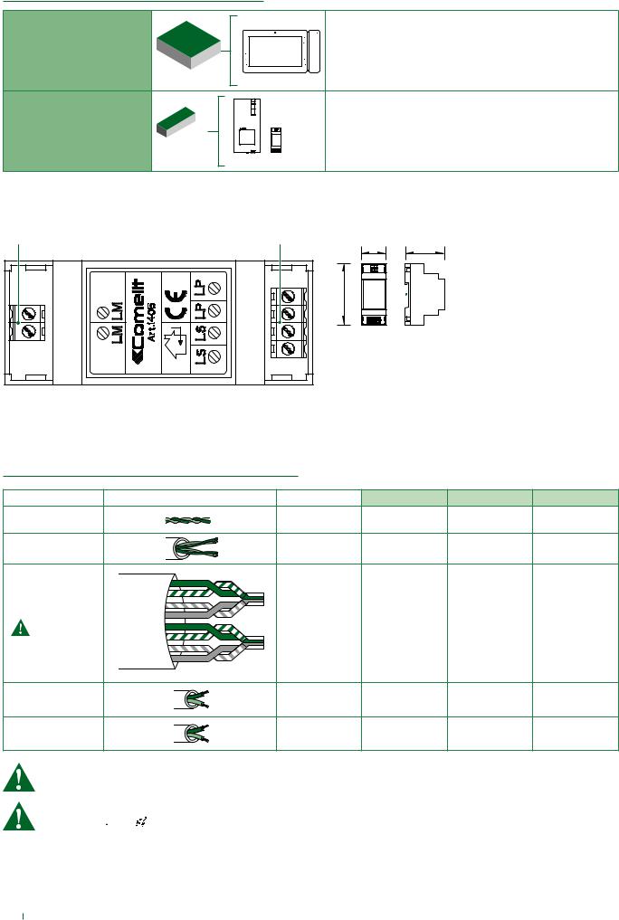
2.4.1 1405 Video splitter |
|
|
|
1. |
2. |
|
|
|
|
1.42 in |
2.28 in |
|
|
3.55 in |
|
|
1. |
LM LM Art. 1209/8 connection |
|
|
2. |
LS | LS additional external unit connection |
|
|
|
LP | LP main external unit connection |
|
3. System installation
3.1 OPERATING DISTANCES AND SYSTEM LAYOUT
Wire Assignment |
Wire Assignment |
Wire Type |
A MAX |
B MAX |
C MAX |
SINGLE PAIR CABLE |
|
CAT5 |
557,74 feet |
278,87 feet |
278,87 feet |
|
24AWG |
(170 m) |
(85 m) |
(85 m) |
|
|
|
||||
DOUBLE PAIR |
|
CAT5 |
656,16 feet |
328,08 feet |
328,08 feet |
CABLE |
|
24AWG |
(200 m) |
(100 m) |
(100 m) |
|
GREEN |
|
|
|
|
MULTI PAIR CABLE |
GREEN / WHITE |
|
|
|
|
ORANGE / WHITE |
|
|
|
|
|
|
ORANGE |
CAT5 |
1.115,48 feet |
557,74 feet |
557,74 feet |
|
|
||||
|
BLU |
24AWG |
(340 m) |
(170 m) |
(170 m) |
FOLLOW THE COLORS |
BLU / WHITE |
|
|
|
|
SHOWN IN THE DIAGRAM! |
|
|
|
|
|
|
|
|
|
|
|
|
BROWN / WHITE |
|
|
|
|
|
BROWN |
|
|
|
|
NON-BRAIDED |
|
AWG22 |
787,40 feet |
393,70 feet |
393,70 feet |
CABLE |
|
(240 m) |
(120 m) |
(120 m) |
|
|
|
||||
NON-BRAIDED |
|
AWG18 |
787,40 feet |
393,70 feet |
393,70 feet |
CABLE |
|
(240 m) |
(120 m) |
(120 m) |
|
|
|
NOTE: This system is capable to expanding up to 4 external units and 8 internal units. For alternative application please consult our technical support engineer first.
At the first connection on the riser, the internal units automatically acquire theirs sub-addresses.
The LEDs 


 and
and 


 flash simultaneously for some seconds. After the procedure the LEDs will turn off.
6
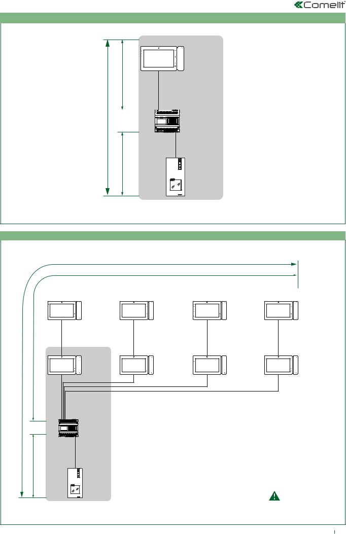
3.1.1 Single-User Kit Art. HFX-9000M
EX-9000H
B
A 


 1209/8
C
EX-DSM
HFX-9000M
3.1.2 Maximum Expansion Monitors in Daisy Chain connection
|
EX-9000H |
EX-9000H |
EX-9000H |
EX-9000H |
|
expansion monitor |
expansion monitor |
expansion monitor |
expansion monitor |
B |
|
|
|
|
|
EX-9000H |
EX-9000H |
EX-9000H |
EX-9000H |
A |
|
expansion monitor |
expansion monitor |
expansion monitor |
|
|
|
|
|
|
1209/8 |
|
|
|
C |
EX-DSM |
|
|
|
|
|
|
|
Maximum 2 monitors |
|
HFX-9000M |
|
|
per output |
|
|
|
|
|
|
|
|
|
7 |

The Art. EX-DSQ is the Additional External Unit for Single-User Kits and contains the external unit Art. EX-DSM and the Video splitter Art. 1405
+
EX-DSQ
EX-DSM 1405
3.1.3 Full System Expansion Diagram
EX-9000H |
EX-9000H |
EX-9000H |
EX-9000H |
EX-9000H |
EX-9000H |
EX-9000H |
EX-9000H |
expansion monitor |
expansion monitor |
expansion monitor |
expansion monitor |
expansion monitor |
expansion monitor |
expansion monitor |
B
A |
|
|
|
1209/8 |
|
|
|
|
|
EX-DSQ |
EX-DSQ |
EX-DSQ |
|
|
|
|
|
expansion external unit |
expansion external unit |
expansion external unit |
|
|
|
|
|
|
|
|
|
|
|
|
|
|
|
1405 |
1405 |
1405 |
|||
C |
EX-DSM |
EX-DSM |
EX-DSM |
EX-DSM |
HFX-9000M
8
 Loading...