

Page 1
Rider's Manual (US Model)
HP4 RACE
BMW Motorrad
Page 2

Motorcycle/Retailer Data
Motorcycle Data
Model
Vehicle identification number
Color number
Initial operation
Number on fork bridge
Retailer Data
Contact in Service
Ms./Mr.
Phone number
Retailer's address/phone number (company stamp)
Page 3

Welcome to BMW
We are pleased that you have
chosen a BMW Motorrad vehicle
and welcome you to the family of
BMW riders. Familiarize yourself
with your new vehicle so that you
can ride safely and confidently on
the racing track.
About this Rider's Manual
Read this Rider's Manual before
you start your new BMW. It contains important information about
operating the vehicle that will
enable you to make full use of
the technical advantages of your
BMW.
It also provides information about
vehicle maintenance and care,
operating safety, and tips on
how best to preserve the value
of your vehicle.
Documentation confirming performance of scheduled maintenance is a precondition for gen-
erous handling of out-of-warranty
claims and goodwill warranty
treatment.
If you want to sell your BMW one
day, remember to hand over this
Rider's Manual too. It is an important element of the motorcycle.
Feedback and comments
Should you have any questions
about your vehicle, your authorized BMW Motorrad retailer is
always happy to provide you with
advice and support.
We wish you many miles of pleasure and satisfaction with your
new BMW, along with a safe and
enjoyable ride,
BMW Motorrad.
01 40 8 406 647
*01408406647*
Page 4

Table of Contents
1 General instructions . ... 5
Overview . . . . . . . .. . . . . .. . . . . .. 6
Abbreviations and
symbols . . . . . . . .. . . . . .. . . . . .. . 6
Technical data . . .. . . . . . .. . . . . 7
Notice concerning current sta-
tus . . . . . . .. . . . . .. . . . . .. . . . . .. . 7
Welcome to BMW Motorrad
M Sport . . . . .. . . . . .. . . . . .. . . . . 7
2 Overviews . .. .. .. .. . .. .. .. 9
Overall view, left side . . .. . . . . 11
Overall view, right side . . . . . . 13
Overall view without trim
panel . . . . . . .. . . . . . .. . . . . .. . . . 15
Underneath seat . . . . . . . .. . . . 16
Left multifunction switch -
front . . .. . . . . . .. . . . . .. . . . . .. . . 17
Left multifunction switch -
rear. . . . . .. . . . . .. . . . . .. . . . . . .. 18
Multifunction switch,
right . . . . . . .. . . . . .. . . . . .. . . . . . 19
Instrument panel . . . . . . . .. . . . 20
3 Displays . . .. .. .. .. .. .. .. . 21
Indicator and warning
lights . . . . .. . . . . .. . . . . . .. . . . . . 22
Multifunction display rider
view . . . . . . .. . . . . .. . . . . .. . . . . . 23
Warning lights . . . . .. . . . . .. . . . 24
4 Operation . .. .. .. . .. .. .. .. 31
Ignition switch . . . .. . . . . .. . . . . 32
Emergency on/off switch (kill
switch) . . . . . .. . . . . . .. . . . . .. . . 32
Multifunction display . . . . . . .. 34
Dynamic Traction Control
(DTC) . . . . . . .. . . . . .. . . . . .. . . . 36
Riding mode . . . . . . .. . . . . .. . . 37
Rider's seat . . . . . . . .. . . . . .. . . 38
5 Setting .. .. .. .. .. . .. .. .. .. 39
Brakes . . . .. . . . . .. . . . . .. . . . . . 40
Steering damper . . . . .. . . . . .. 40
Stub handlebars . .. . . . . .. . . . . 41
Observe the adjustment
range on the telescopic
forks. . . . .. . . . . .. . . . . .. . . . . .. . 42
Steering head angle . . .. . . . . . 43
Fork bridge offset . . . . . . .. . . . 53
Spring preload . . . .. . . . . .. . . . 56
Damping . . . . .. . . . . .. . . . . .. . . 58
Ride height . .. . . . . . .. . . . . .. . . 61
Footrests . . .. . . . . .. . . . . .. . . . . 65
Foot piece for footbrake
lever .. . . . . .. . . . . . .. . . . . .. . . . . 66
Footbrake lever height . . . . . . 67
Foot piece for gearshift
lever .. . . . . .. . . . . . .. . . . . .. . . . . 68
Gearshift lever height. . . . . .. . 68
Seat height . .. . . . . .. . . . . .. . . . 69
Swinging arm . . . . . . . .. . . . . .. 70
6 Riding .. .. .. .. .. . .. .. .. .. . 75
Safety information . . .. . . . . . .. 76
Checklist . . . . . .. . . . . .. . . . . .. . 77
Starting. . . . .. . . . . .. . . . . .. . . . . 77
Bringing the engine up to
operating temperature. . . . .. . 79
Running in . . . .. . . . . .. . . . . .. . 79
Shifting gears . . . . . .. . . . . .. . . 80
Brakes . . . .. . . . . .. . . . . .. . . . . . 81
Start of race . . .. . . . . . .. . . . . .. 82
Speed limiter for pit lane . . . . 84
Page 5

Parking your motorcycle . . . . 84
7 In the pit ... . .. .. .. .. .. .. . 87
Refueling . . . . .. . . . . .. . . . . .. . . 88
Displays for the mechatron-
ics technician. . . . .. . . . . . .. . . . 90
Displays for the mechatron-
ics technician. . . . .. . . . . . .. . . . 92
DTC. . . . . .. . . . . . .. . . . . .. . . . . . 93
EBR . . . . .. . . . . .. . . . . .. . . . . . .. 93
Gearshift-pattern
reverser . . . .. . . . . . .. . . . . .. . . . 94
Data recording and 2D soft-
ware .. . . . . .. . . . . .. . . . . .. . . . . . 95
HP Race
Calibration Kit Pro . . . . . .. . . . . 96
Connector for optional ac-
cessories . . . . .. . . . . .. . . . . .. . . 96
Securing motorcycle for
transport . . . . . .. . . . . . .. . . . . .. 96
8 Technology in
detail .. . .. .. .. .. .. .. .. . .. . 99
Lightweight construc-
tion . .. . . . . . .. . . . . .. . . . . .. . . 100
Dynamic Traction Control
(DTC) . . . . . . .. . . . . .. . . . . .. . 100
Engine brake (EBR) . . . . . .. 101
Riding mode . . . . . . .. . . . . .. 101
Pro gearshift assistant . .. . . 102
9 Maintenance . . . .. .. .. . 105
General notes . . . . . .. . . . . .. 106
Rear-wheel stand . . . . . . . .. 106
Engine oil . . . . . . .. . . . . .. . . . 107
Brake system . . . .. . . . . .. . . 108
Cleaning the brakes . . . . . . . 117
Clutch . . . . .. . . . . .. . . . . .. . . . 121
Coolant. . . . . .. . . . . .. . . . . .. . 122
Tires . . . . . .. . . . . .. . . . . .. . . . 123
Rims and tires . .. . . . . .. . . . . 123
Wheels . . . . . .. . . . . .. . . . . .. . 123
Fairings and panels . . . . .. . 128
Jump-starting . . . . .. . . . . .. . 133
Battery . . . . . . .. . . . . .. . . . . .. 134
Fuse . . . . . . . .. . . . . .. . . . . .. . 137
Data link connector . . . . . .. 138
Chain. . . . . . .. . . . . .. . . . . .. . . 139
10 Accessories . . .. .. .. . 143
General notes . . . . . .. . . . . .. 144
Connections for additional
sensors. . . .. . . . . . .. . . . . .. . . 144
Connection for CAN-Bus
signal .. . . . . .. . . . . .. . . . . .. . . 145
Connection for infrared re-
ceiver . . . .. . . . . .. . . . . .. . . . . 145
11 Care . .. . .. .. .. .. .. .. .. 147
Care products . . . . .. . . . . .. . 148
Washing your motorcy-
cle. . . . . .. . . . . .. . . . . .. . . . . .. 148
Cleaning sensitive motorcy-
cle parts . . .. . . . . .. . . . . .. . . . 148
Paint care . . . .. . . . . .. . . . . . . 149
Protective wax coating . . . . 150
Store motorcycle . . . .. . . . . . 150
Return motorcycle to
use . . . .. . . . . . .. . . . . .. . . . . .. 150
12 Technical data . . .. .. 151
Screw connections . . . .. . . . 152
Chassis and suspension
configuration data . . . . .. . . . 159
Fuel . . . . .. . . . . .. . . . . .. . . . . . 163
Page 6

Engine oil . . . . . . .. . . . . .. . . . 163
Engine . . . . . . .. . . . . .. . . . . .. 164
Clutch . . . . .. . . . . .. . . . . .. . . . 165
Transmission . . . .. . . . . .. . . . 165
Rear-wheel drive . . . . . . .. . . 166
Frame . . . . . .. . . . . .. . . . . .. . . 166
Chassis and
suspension . . . . .. . . . . .. . . . . 167
Brakes . . . .. . . . . .. . . . . .. . . . 168
Wheels and tires . . . . .. . . . . 169
Electrical system . . . . . .. . . . 170
Dimensions . . . .. . . . . .. . . . . 170
Weights . . . . . .. . . . . .. . . . . .. 171
13 Service . . .. .. .. .. . .. .. 173
Reporting safety
defects . . . . . .. . . . . .. . . . . .. . 174
BMW Motorrad Service . . . 175
Maintenance proce-
dures . . .. . . . . .. . . . . .. . . . . .. 175
Maintenance schedule . . . . 179
Maintenance confirma-
tions. . . . . .. . . . . .. . . . . .. . . . . 180
Service confirmations . . . . . 194
14 Index . .. .. .. .. .. .. .. .. 196
Page 7

General instructions
Overview . . . . . . .. . . . . .. . . . . . .. . . . . .. . 6
Abbreviations and symbols . .. . . . . .. . 6
Technical data . . . .. . . . . . . . . . . . .. . . . . . 7
Notice concerning current status . . . . 7
Welcome to BMW Motorrad M
Sport . . . . . . . . . . .. . . . . . . . . . . . .. . . . . . .. 7
1
5
z
General instructions
Page 8
Overview
1
Chapter 2 of this Rider's Manual will provide you with an ini-
6
tial overview of your motorcycle.
All maintenance and repair work
carried out on your motorcycle
will be documented in Chapter
13. Documentation confirming performance of scheduled
maintenance is a precondition
for generous handling of out-ofwarranty claims and goodwill warranty treatment.
When the time comes to sell
your BMW, please remember
to hand over this Rider's Manual;
it is an important part of the mo-
z
General instructions
torcycle.
Abbreviations and symbols
CAUTION Hazard with
low risk. Failure to avoid
this hazard can result in minor or
moderate injury.
WARNING Hazard with
moderate risk. Failure to
avoid this hazard can result in
death or serious injury.
DANGER Hazard with high
risk. Failure to avoid this
hazard results in death or serious
injury.
ATTENTION Special in-
structions and precautionary measures. Non-compliance
can cause damage to the vehicle or accessories and warranty
claims may be denied as a result.
NOTICE Special informa-
tion on operating and inspecting your motorcycle as well
as maintenance and adjustment
procedures.
Indicates the end of an
item of information.
Instruction.
Result of an activity.
Reference to a page with
more detailed information.
Indicates the end of accessory or equipmentdependent information.
Tightening torque.
Technical data.
OA Optional accessory.
BMW Motorrad optional
accessories can be purchased and installed at
your authorized BMW
Motorrad retailer.
NV National-market version.
Page 9

DTC Dynamic Traction Con-
trol.
EBR Engine Brake
Engine brake
Technical data
All dimensions, weights and performance data contained this
Rider's Manual refer to the German DIN standards and comply
with their tolerance specifications.
Versions for individual countries
may differ.
Notice concerning current status
The high safety and quality standards of BMW motorcycles are
maintained by consistent, ongoing development efforts embracing their design, equipment
and accessories. For this reason,
some aspects of your motorcycle
may vary from the descriptions in
this Rider's Manual. In addition,
BMW Motorrad cannot guarantee
the total absence of errors. We
hope you will appreciate that no
claims can be recognized based
on the data, illustrations or descriptions in this manual.
Welcome to BMW Motorrad M Sport
The world of racing is fascinating. However, it also entails certain risks. A number of things
need to be kept in mind so that
you can enjoy racing and ensure lasting enjoyment from your
HP4 Race.
The HP4 Race is a pure racing
vehicle. This means that technical equipment that is fitted in
road-approved motorcycles to
improve comfort and safety is
missing or designed differently.
This includes:
As is common in motorsports,
the motorcycle does not have
ABS.
The cooling system does not
have an electrical fan. If the
coolant temperature becomes
too high, the engine has to be
turned off; it may be necessary
to provide external cooling.
The engine has upper and
lower thermal limits. Warning lights and displays in the
instrument cluster indicate
whether the current values
have exceeded or dropped
below these limits. Only ride
the motorcycle in the "green"
range of the coolant temperature.
The motorcycle can only be
operated in a limited temperature range. Observe the safety
information. ( 77)
The engine does not have
knock control. Always use the
1
7
z
General instructions
Page 10

prescribed fuel grade and octane number.
1
The DTC intervenes much
8
later than the well-known
S 1000 RR. This helps provide
maximum performance with
slick tires. You need to
gradually familiarize yourself
with this feature
The starter does not have engine starting suppression. If a
gear is engaged, the motorcycle can set off when the starter
button is pressed. Furthermore, an installed tire heater
could be damaged. In order to
start the vehicle, pull the clutch
or, better still, shift to neutral.
z
General instructions
The shift pattern is inverted as
the factory setting. This means
that 1st gear is shifted upward
and gears 2 to 6 are shifted
downward.
The HP Pro gearshift assistant allows you to shift up and
down between gears without
the clutch.
The brakes need to be cleaned
on a regular basis. Observe the
information in the Maintenance
chapter. ( 117)
The motorcycle does not have
a side stand. The supplied
rear-wheel stand must be used
for parking
The HP4 Race provides a
variety of adjustment options
for geometry, chassis and
suspension and engine control.
Each time the settings are
changed, this can impair the
drivability or even cause a crash.
Only make changes to the
settings in minor steps and only
ever to one component at a time.
Observe the safety information
for this motorcycle.
Page 11

Overviews
Overall view, left side .. . . . . . . . . . . . .. 11
Overall view, right side . . . . .. . . . . .. . . 13
Overall view without trim panel. . . . . . 15
Underneath seat . . . . . . .. . . . . . .. . . . . . 16
Left multifunction switch - front . . . . . 17
Left multifunction switch - rear . . .. . . 18
Multifunction switch, right . . . .. . . . . . . 19
Instrument panel . . . . . .. . . . . . . . . . . . .. 20
2
9
z
Overviews
Page 12
2
10
z
Overviews
Page 13

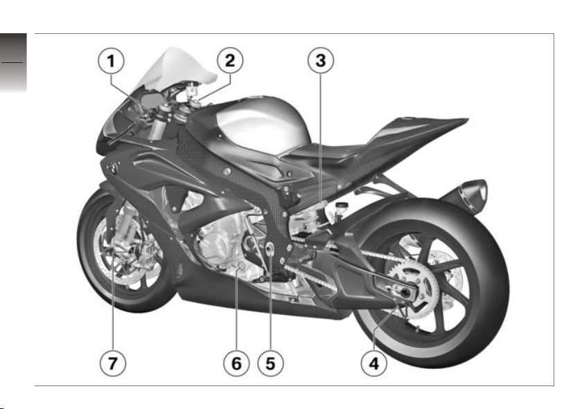
Overall view, left side
1 Setting the handlebar off-
set ( 41)
2 Adjuster for spring preload,
front ( 56)
3 Adjusting the rear
rebound-stage damping
( 59)
Adjusting the rear compression damping ( 60)
Adjuster for spring preload,
rear ( 57)
4 Bracket for auxiliary stand
( 106) ( 106)
5 Setting the swinging arm
pivot point ( 71)
6 Engine oil indicator
( 107)
7 Adjusting the front
rebound-stage damping
( 58)
Adjusting the front compression damping ( 59)
2
11
z
Overviews
Page 14
2
12
z
Overviews
Page 15

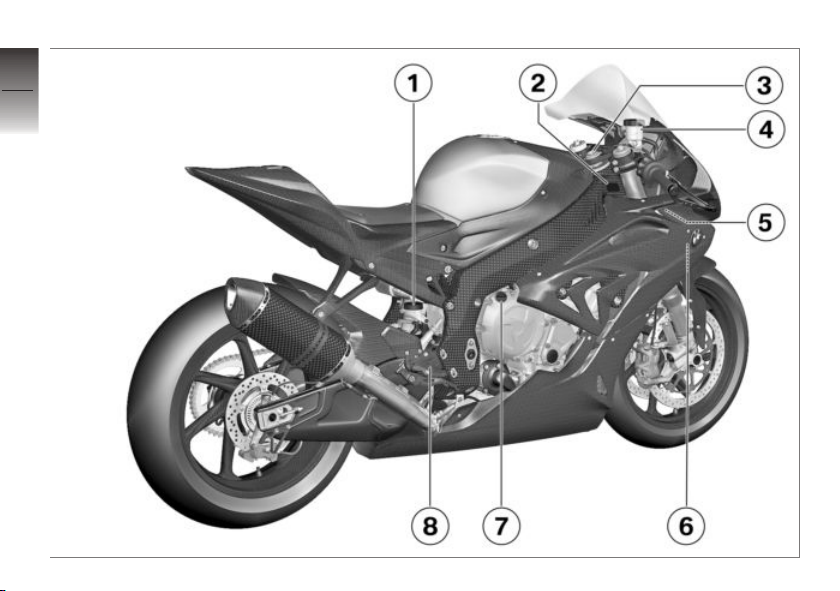
Overall view, right side
1 Brake-fluid reservoir, rear
( 111)
2 Vehicle identification num-
ber and type plate (on
steering head at right)
3 Adjusting the steering
head angle. ( 43)
Adjusting the fork bridge
offset. ( 53)
4 Brake fluid reservoir, front
( 110)
5 Adjusting the steering
damper. ( 40)
6 Checking the coolant level.
( 122)
7 Oil filler opening ( 108)
8 Adjusting the footrests.
( 65)
2
13
z
Overviews
Page 16
2
14
z
Overviews
Page 17

Overall view without trim panel
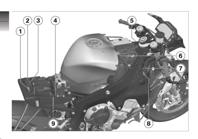
1 Fuse ( 137)
2 Starter motor relay
3 Main relay
4 Connector for rear brake
pressure sensor ( 144)
5 Connector for front spring
travel sensor ( 144)
6 Connector for CAN bus
signal and voltage supply
( 145)
7 Connector for front brake
pressure sensor ( 144)
8 Connector for infrared re-
ceiver ( 145)
9 Connector for rear spring
travel sensor ( 144)
2
15
z
Overviews
Page 18
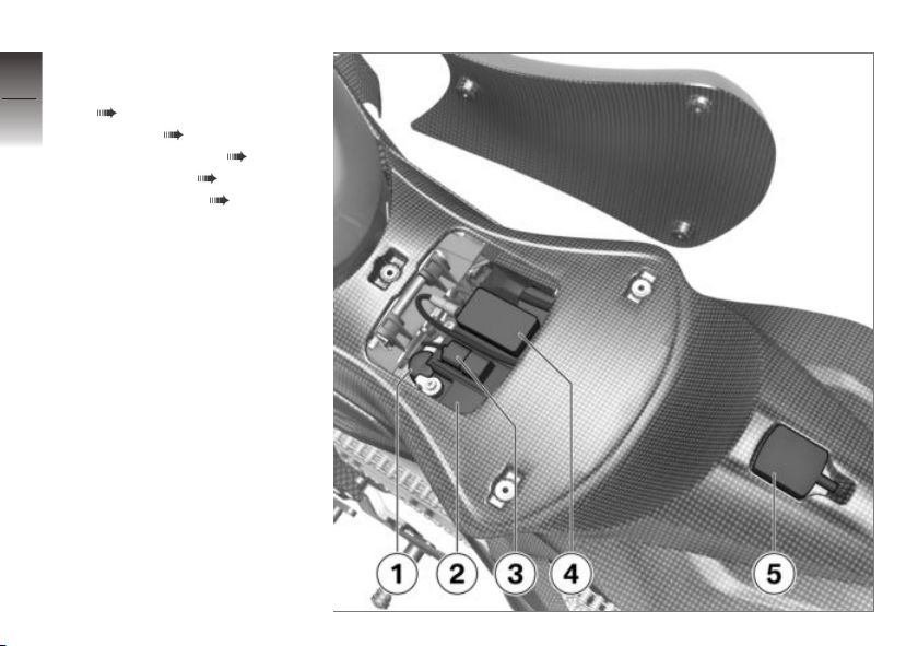
Underneath seat
2
1 Data link connector
16
z
Overviews
( 138)
2 Battery ( 134)
3 USB connector ( 95)
4 Data logger ( 95)
5 GPS receiver ( 95)
Page 19
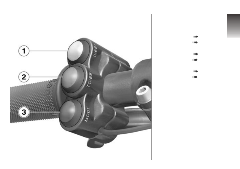
Left multifunction switch - front
1 TC/EB- button
Adapt DTC ( 93).
Adapt EBR ( 94).
2 TC/EB+ button
Adapt DTC ( 93).
Adapt EBR ( 94).
3 MODE button
Adapt DTC ( 93).
Adapt EBR ( 94).
2
17
z
Overviews
Page 20
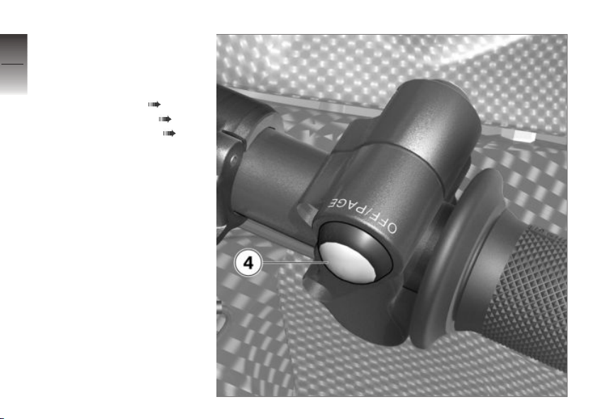
Left multifunction
2
switch - rear
18
4 OFF/PAGE button
Selecting displays in multifunction display ( 35).
Deactivating DTC ( 36).
Switching on DTC ( 36).
z
Overviews
Page 21
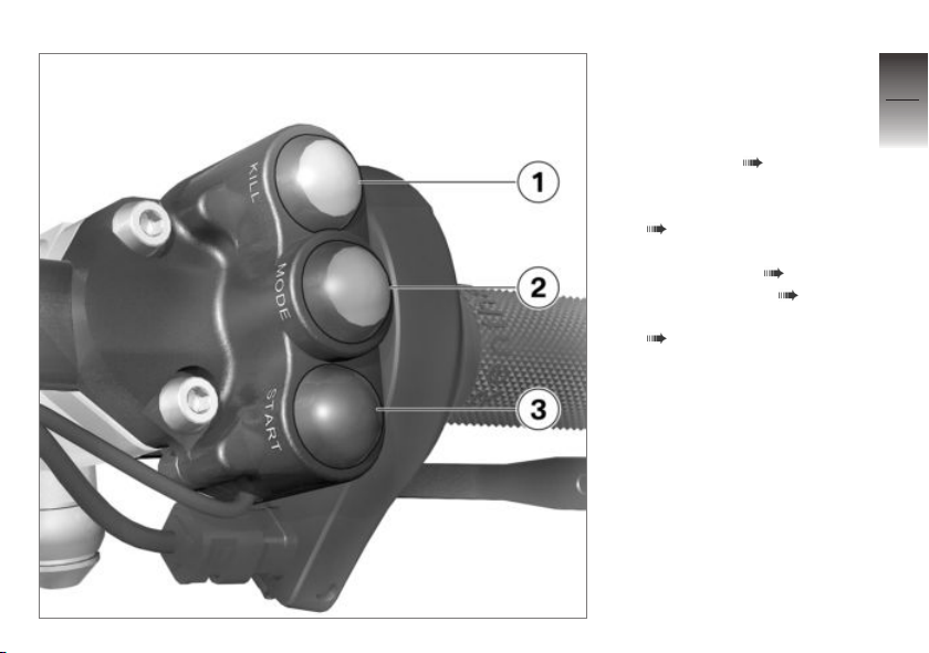
Multifunction switch, right
1 KILL button
Emergency on/off switch
(kill switch) ( 32)
2 MODE button
Selecting riding mode
( 37)
3 START button
Start engine. ( 77)
Launch Control ( 83)
Speed limiter for pit lane
( 84)
2
19
z
Overviews
Page 22
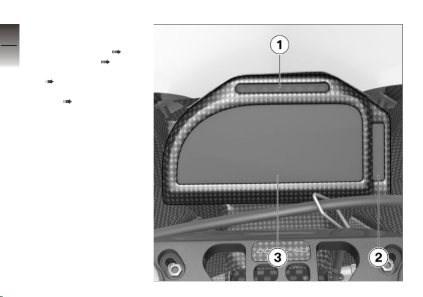
Instrument panel
2
1 LED band: for visualization
20
z
Overviews
of the speed limit ( 80)
Shiftpoint light ( 80)
2 Indicator and warning lights
( 22)
3 Multifunction display rider
view ( 23)
Page 23

Displays
Indicator and warning lights . . . . . . .. . 22
Multifunction display rider view . . . . . 23
Warning lights . . . .. . . . . . . . . . . . .. . . . . 24
3
21
z
Displays
Page 24
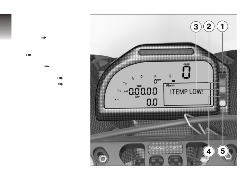
Indicator and warning
3
lights
22
1 Coolant temperature cold
(blue) ( 24)
2 Fuel reserve or battery
voltage too low (orange)
( 27)
3 Light for the fastest lap
(green) ( 27)
4 Coolant or oil temperature
z
Displays
too high (red) ( 24)
5 DTC (orange) ( 29)
Page 25
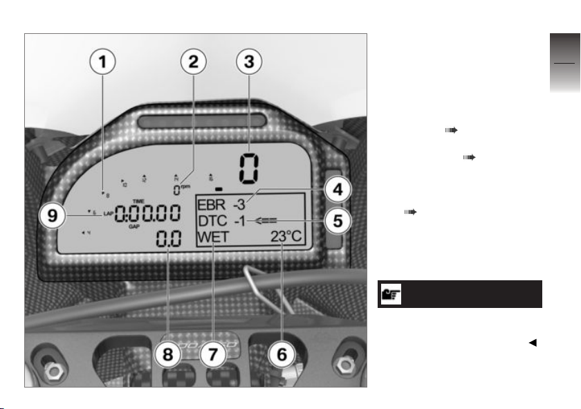
Multifunction display rider view
1 Tachometer bar chart
2 Digital tachometer
3 Gear indicator
4 Engine brake EBR status
display ( 94)
5 Traction control DTC sta-
tus display ( 36)
6 Coolant temperature
7 Riding mode
Setting the riding mode.
( 37)
8 Difference between previ-
ous lap time and best lap
time
9 Current lap time
NOTICE
Information about the display
modes for mechatronics technician is provided in Chapter 7.
3
23
z
Displays
Page 26
Warning lights
3
Displays
24
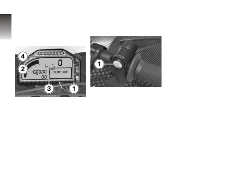
Warnings are displayed with appropriate warning lights.
z
Displays
In addition to the warning light 1,
an alarm 2 is displayed in the
multifunction display with the
corresponding warning 3. In
addition, depending on the alarm,
the two respective external
LEDs 4 of the LED band flash.
If several warnings are active, all
corresponding warning lights are
displayed; warnings are rotated in
the display.
You will find an overview of the
potential warnings on the following pages.
The warning and the LEDs can
be suppressed by pressing the
OFF/PAGE button 1. The warning light remains lit up. If the
OFF/PAGE button 1 is pressed
again, the warning is displayed
again.
Page 27
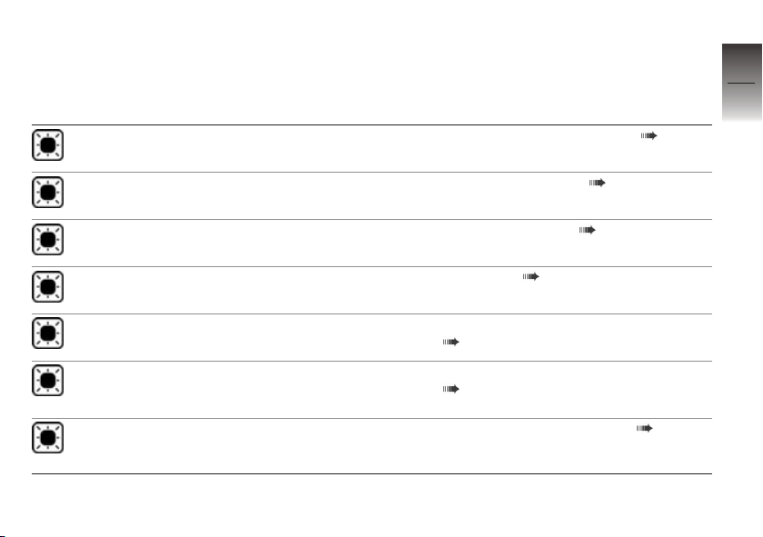
Overview of warning indicators
Indicator and warning
Display text Meaning
lights
Blue warning light
lights up.
Orange warning
light (top) lights up.
Orange warning
light (top) lights up.
Green indicator
light lights up.
Red warning light
lights up.
Red warning light
lights up.
Red warning light
lights up.
!TEMP LOW! is displayed.
!FUEL! is displayed.
!UB LOW! is displayed.
!TWAT HIGH! is
displayed.
!ENGINE! is displayed. LED flashing.
!TOIL HIGH!
is displayed.
LED flashing.
Coolant temperature too cold ( 27)
Fuel down to reserve ( 27)
Low battery voltage ( 27)
Fastest lap ( 27)
Coolant temperature above 104 °C
( 28)
Coolant temperature above 115 °C
( 28)
Engine temperature too high ( 28)
3
25
z
Displays
Page 28
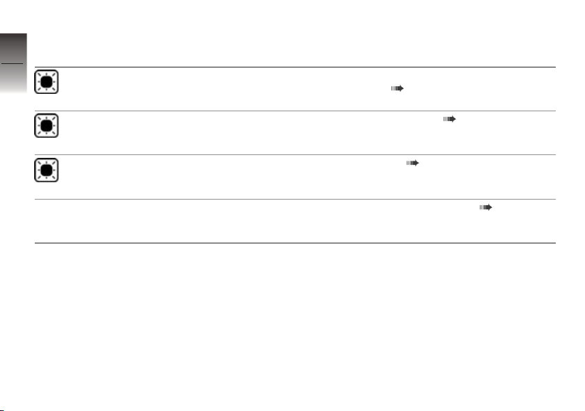
Indicator and warning
3
lights
26
z
Displays
Red warning light
lights up.
Orange warning
light (bottom) lights
up.
Orange warning
light (bottom) lights
up.
Display text Meaning
!POIL! is displayed. LED flashing.
!DTC OFF! is displayed.
!DTC ERROR!
is displayed.
LED flashing.
!LAUNCH! is displayed. LED flashing.
Oil pressure too low (with sensor installed) ( 29)
DTC switched off ( 29)
DTC error ( 29)
Launch Control activated ( 29)
Page 29
Coolant temperature too
cold
Blue warning light for
coolant temperature too
low lights up.
!TEMP LOW! is displayed.
Possible cause:
The engine may only be
moved in the optimum
temperature window. The
coolant and engine oil must
be warmed up by running the
engine in neutral. ( 79)
Fuel down to reserve
Orange warning light (top)
lights up.
!FUEL! is displayed.
WARNING
Rough engine running or
switching off of the engine
due to a lack of fuel
Accident hazard
Do not drive to the extent that
the fuel tank is completely
empty.
Possible cause:
At the most, the fuel tank still
contains the reserve fuel quantity.
Fuel reserve
Approx. 1.1 gal (Approx. 4 l)
Refueling ( 88).
Low battery voltage
Orange warning light (top)
lights up.
!UB LOW! is displayed.
Possible cause:
WARNING
Rough engine running or
switching off of the engine
due to low battery voltage
Accident hazard
If the warning flashes, ride the
motorcycle to the pit at the
next opportunity.
The orange warning light lights
up if the vehicle voltage drops
below 12.2 V. Check voltage
regulator and AC alternator.
Fastest lap
Green indicator light for
fastest lap lights up.
When you start a new lap, your
intermediate times are taken at
regular intervals and compared
with the corresponding intermediate times of the best lap stored
in memory. If your intermediate
times show that you are faster
than on your previous best lap,
the processor anticipates that
this lap will be your new best
time. The green indicator light
lights up.
3
27
z
Displays
Page 30
Coolant temperature
3
above 104 °C
28
Red warning light for
coolant temperature too
high lights up (temperature
higher than 104 °C).
!TWAT HIGH! is displayed.
Coolant temperature
above 115 °C
z
Displays
Red warning light for
coolant temperature too
high lights up (temperature
higher than 115 °C).
!ENGINE! is displayed.
LED flashing.
ATTENTION
Riding with overheated engine
Irreparable engine damage
Only carry on riding in partial
load range.
Possible cause:
The coolant temperature is too
high.
If possible, drive back to the pit
in the part-load range to cool
down the engine, but not too
slowly.
As the motorcycle does not
have an electrical fan in order to save weight, the engine
must not be left running for too
long when still. If the coolant
temperature is too high, it may
be necessary to cool the radiator using a fan or blower.
Should the coolant temperature
frequently be too high, have
the fault rectified as quickly
as possible by an authorized
workshop, preferably an authorized BMW Motorrad retailer.
Engine temperature too
high
Red warning light lights up.
!TOIL HIGH! is displayed.
LED flashing.
ATTENTION
Riding with overheated engine
Irreparable engine damage
Only carry on riding in partial
load range.
Possible cause:
If possible, drive back to the pit
in the part-load range to cool
down the engine.
Check cooling system, particularly oil cooler.
Page 31
Oil pressure too low (with
sensor installed)
Red warning light lights up.
Possible cause:
ATTENTION
Riding with insufficient oil
pressure
Engine damage
Do not continue riding.
Stop the motorcycle immedi-
ately and turn off engine.
Have fault eliminated at a specialist service facility, preferably
an authorized BMW Motorrad
retailer.
DTC switched off
Orange warning light for
DTC lights up.
!DTC OFF! is displayed.
Possible cause:
The DTC system was deacti-
vated by the rider.
Switching on DTC ( 36).
DTC error
Orange warning light for
DTC lights up.
!DTC ERROR! is displayed.
LED flashing.
Possible cause:
The control unit has detected a
fault with the DTC. It must be
noted that the DTC function is
not available at all or is restricted.
It remains possible to continue
riding. You should also observe
the additional information on
situations that can lead to a
DTC fault ( 100).
Have the malfunction corrected
as soon as possible at an
authorized service facility,
preferably an authorized
BMW Motorrad Retailer.
Launch Control activated
!LAUNCH! is displayed.
LED flashing.
3
29
z
Displays
Page 32

3
30
z
Displays
Page 33

Operation
Ignition switch . . . . . . .. . . . . . .. . . . . .. . 32
Emergency on/off switch (kill
switch) . . . .. . . . . . .. . . . . .. . . . . . .. . . . . . 32
Multifunction display . . . . . . .. . . . . .. . . 34
Dynamic Traction Control (DTC) . . . . 36
Riding mode . . . . . . .. . . . . .. . . . . . .. . . . 37
Rider's seat . . . . . . .. . . . . . . . . . . . .. . . . . 38
4
31
z
Operation
Page 34
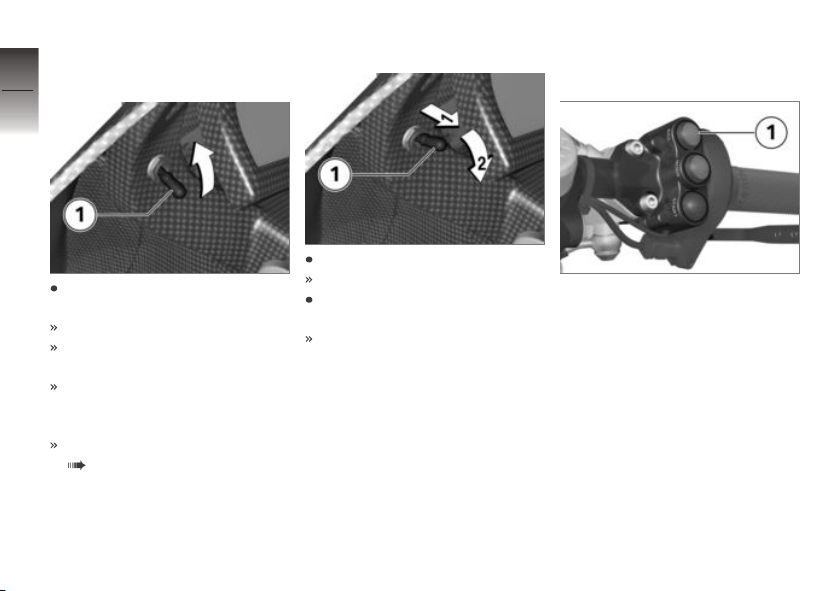
Ignition switch
4
Switching on ignition
32
z
Operation
Set ignition switch 1 in top position.
Reset safeguard engages.
All function circuits are turned
on.
Engine can be started if the
emergency off switch is in normal operating position.
Pre-Ride-Check is carried out.
( 78)
Switch off ignition
Pull ignition switch 1.
Reset safeguard is released.
Set ignition switch 1 in bottom
position.
All function circuits are turned
off.
Emergency on/off switch (kill switch)
1 Emergency on/off switch
(kill switch)
The engine can be switched
off easily and quickly using the
emergency on/off switch.
Page 35
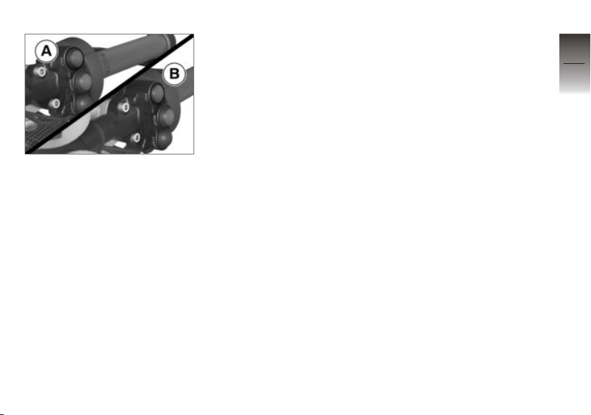
A Engine is switched off
B Operating position
4
33
z
Operation
Page 36
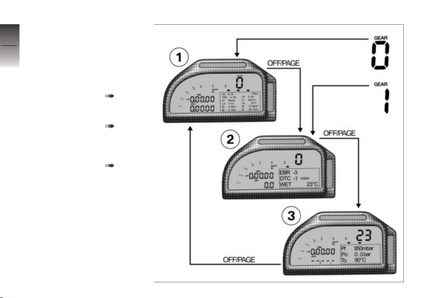
Multifunction display
4
Overview
34
1 Mechatronics technician
view 1
Standard display
Selecting displays in multifunction display ( 35).
2 Rider view
Selecting displays in multifunction display ( 35).
3 Mechatronics technician
z
Operation
view 2
Selecting displays in multifunction display ( 35).
Page 37
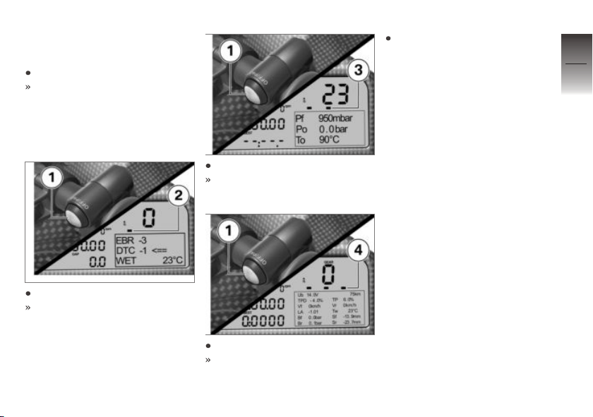
Selecting displays in
multifunction display
Switch on the ignition.
The mechatronics technicians
technician view 1 is automatically displayed in the multifunction display when the motorcycle still in idle position.
Press OFF/PAGE 1 once.
Rider view 2 is displayed.
Press OFF/PAGE 1 once.
Mechatronics technician view
2 3 is displayed.
Press OFF/PAGE 1 once.
Mechatronics technician view
1 4 is displayed.
If a gear is engaged or if the
motorcycle starts to move, the
multifunction display changes
to the rider view. Only this
view can be displayed while
driving.
4
35
z
Operation
Page 38
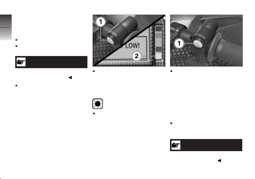
Dynamic Traction
4
Control (DTC)
36
Deactivating DTC
Switch on the ignition.
Emergency off switch must be
in normal operating position.
NOTICE
The DTC function can also be
deactivated while driving.
z
Operation
Change display on the multifunction display to the rider
view.
Keep OFF/PAGE 1 pressed
until the DTC indicator and
warning light 2 lights up and
the warning !DTC OFF! is displayed.
Orange warning light for
DTC lights up.
Release OFF/PAGE 1 within
two seconds.
The warning can be
suppressed by pressing the
OFF/PAGE button 1. The
warning light remains lit up.
If the OFF/PAGE button 1 is
pressed again, the warning is
displayed again.
Switching on DTC
Change display on the multifunction display to the rider
view.
NOTICE
The DTC function can also be
turned on while riding.
Page 39
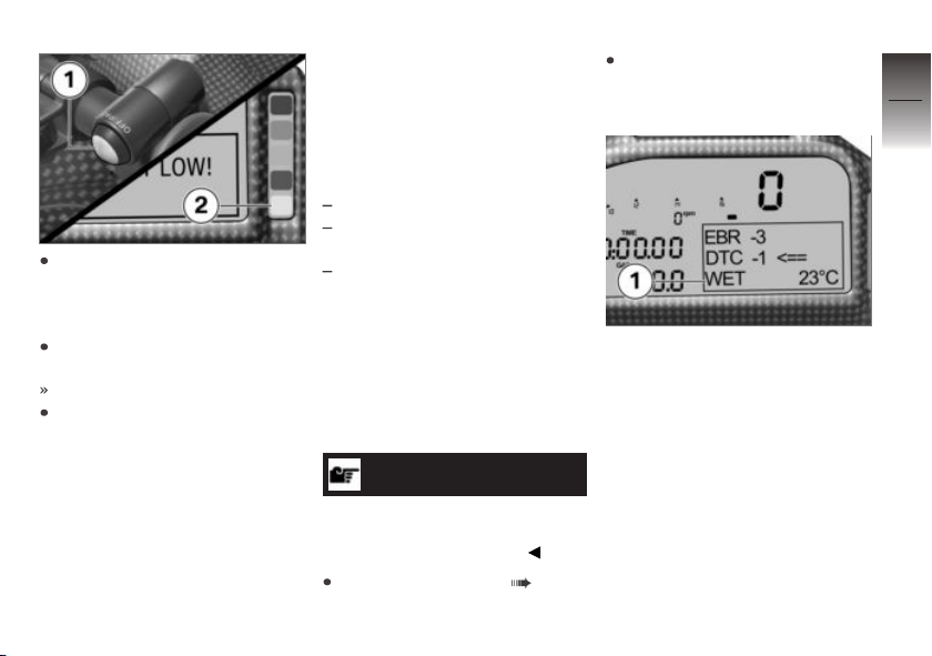
Keep OFF/PAGE 1 pressed
until the DTC indicator and
warning light 2 goes out and
the warning disappears.
Release OFF/PAGE 1 within
two seconds.
DTC activated.
The DTC status is saved by
the control unit; it is restored
after switching the ignition off
and back on. That means that
after turning off DTC, it must
be manually turned on again.
Riding mode
Use of the riding modes
BMW Motorrad has developed
riding scenarios for your motorcycle from which you can select
the one matching your situation:
Riding on wet roads.
When riding on slightly wet or
drying roads.
Riding on dry roads.
The optimum balance between
engine torque, throttle response,
throttle control, DTC control and
EBR control is provided for each
of these scenarios.
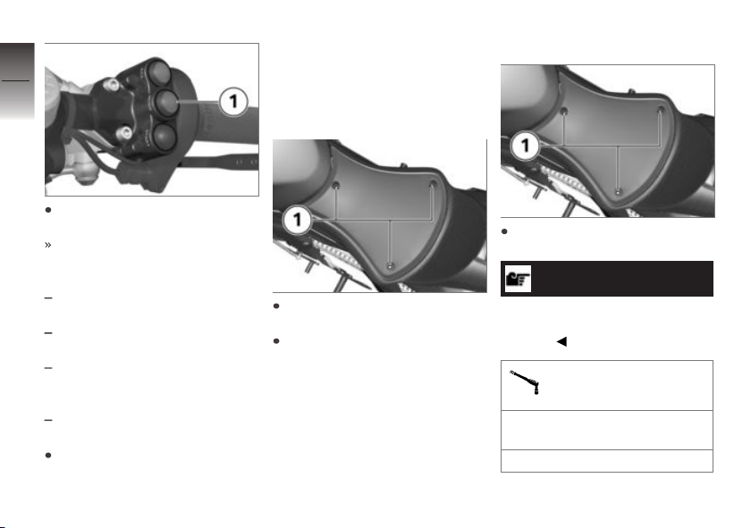
Setting riding mode
NOTICE
Details on the selectable driving
modes are provided in the chapter "Technology in Detail".
Switching on ignition ( 32).
Change display on the multifunction display to the rider
view.
The currently selected riding
mode 1 is displayed in the multifunction display.
4
37
z
Operation
Page 40
4
38
Press MODE 1 twice in quick
succession.
Riding mode is changed.
z
Operation
The following riding modes can
be selected:
WET: When riding on wet roads
with rain tires.
INT: When riding on slightly
wet or drying roads.
DRY1: When riding on dry
roads with softer response
characteristics.
DRY2: When riding on dry
roads with full power.
Repeat process repeatedly until the desired riding mode is
displayed in the multifunction
display.
Rider's seat
Remove rider's seat
Remove bolts 1 and remove
rider's seat.
Lay the rider's seat on a clean
surface with the upholstered
side down.
Installing rider's seat
Attach rider's seat and fit
bolts 1.
NOTICE
Observe torque, otherwise there
is a danger of damage to the carbon part.
Rider's seat on tail section
Joint compound: Lubricate
bolt, Optimoly TA
2 lb/ft (3 Nm)
Page 41

Setting
Brakes . . . . . . .. . . . . .. . . . . . .. . . . . .. . . . 40
Steering damper . . . . . . .. . . . . . . . . . . . . 40
Stub handlebars . . . . .. . . . . .. . . . . . .. . 41
Observe the adjustment range on
the telescopic forks . . . . . . .. . . . . . .. . . 42
Steering head angle . . . .. . . . . . . . . . . . 43
Fork bridge offset . . . . . . . . .. . . . . . .. . . 53
Spring preload . . . . . . . . . . .. . . . . . . . . . . 56
Damping . .. . . . . . .. . . . . . . . . . . . .. . . . . . 58
Ride height . . . . . . . . . . . .. . . . . . . . . . . . . 61
Footrests . . . . . .. . . . . .. . . . . . .. . . . . .. . 65
Foot piece for footbrake lever .. . . . . . 66
Footbrake lever height . . . . . . .. . . . . . . 67
Foot piece for gearshift lever. . . . .. . . 68
Gearshift lever height . . . .. . . . . . .. . . . 68
Seat height . . . . . . . . . . .. . . . . . .. . . . . .. 69
Swinging arm . . . . . . .. . . . . . .. . . . . . . . . 70
5
39
z
Setting
Page 42
Brakes
5
Adjusting brake lever
40
z
Setting
WARNING
Modified position of the
brake fluid reservoir
Air in the brake system
Do not twist the handlebar fitting or the handlebars.
WARNING
Adjusting the brake lever
while driving
Accident hazard
Only adjust the brake lever
when the motorcycle is
stationary.
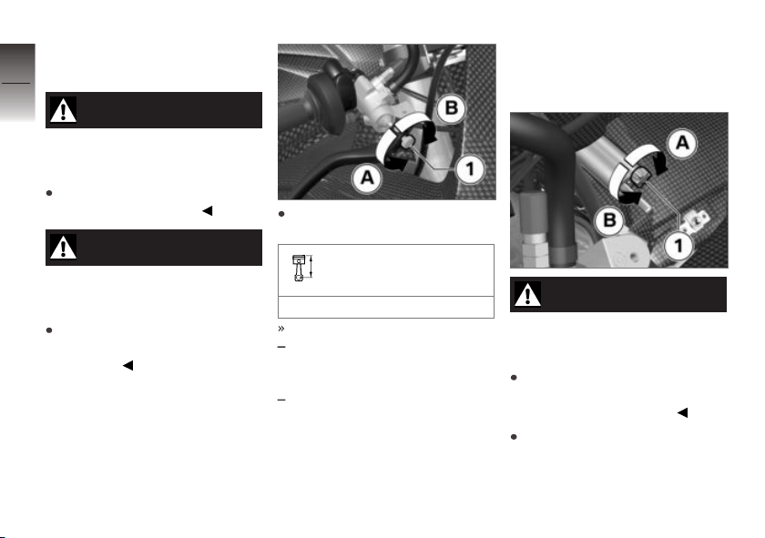
Turn adjusting screw 1 to desired position.
Brake lever adjustment
range
20 stages
Adjustment options:
In direction A: Distance between handlebar grip and brake
lever is reduced.
In direction B: Distance between handlebar grip and brake
lever is increased.
Steering damper
Adjusting the steering
damper
WARNING
Adjusting the steering
damper while riding.
Accident hazard
Never adjust the steering
damper except while the
motorcycle is stationary.
Turn adjustment screw 1 in direction A to increase damping
force.
Page 43
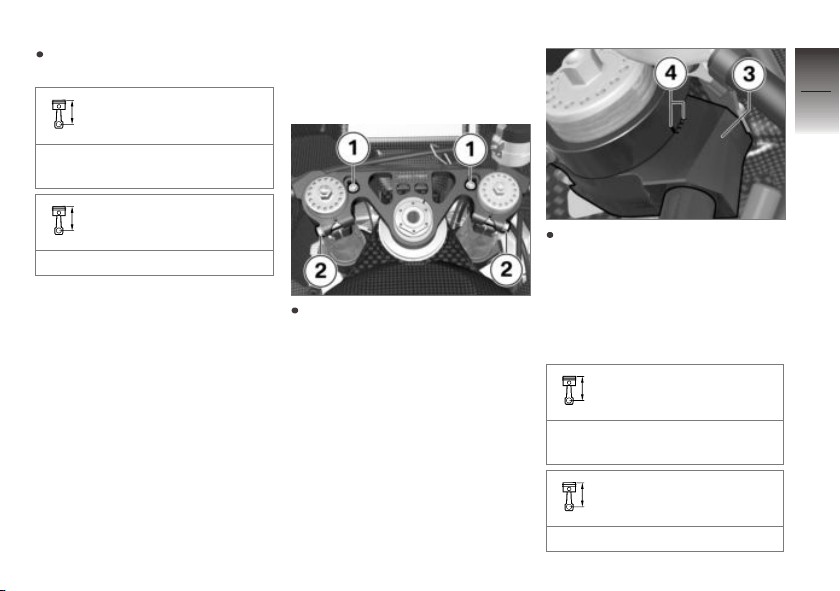
Turn the screw 1 in direction B
to reduce damping force.
Steering damper basic
setting
10 clicks opened (from totally
closed)
Steering damper adjustment range
18 clicks
Stub handlebars
Setting the handlebar
offset
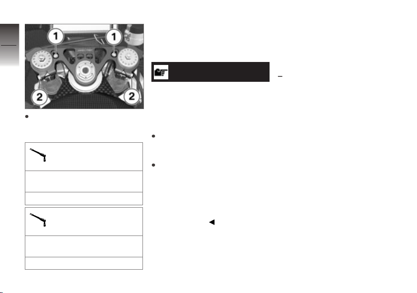
Release screws 1 and
screws 2.
Adjust right handlebar clamp 3
in the area of the markings 4
to the desired position. Adjust
the left handlebar clamp in the
same way and make sure that
both handlebar halves are set
in the same position.
Handlebar offset basic
setting
2nd position of handlebar half
right at rear
Handlebar offset adjustment range
4 positions
5
41
z
Setting
Page 44
5
42
First tighten screws 1 and then
z
Setting
screws 2 to the appropriate
torque.
Locking screw on top
fork bridge
Joint compound: Lubricate
thread, Optimoly TA
6 lb/ft (8 Nm)
Handlebar clamp on fork
leg
Joint compound: Lubricate
thread, Optimoly TA
14 lb/ft (19 Nm)
Observe the adjustment range on the telescopic forks
ATTENTION
Free movement of components in steering range not
guaranteed
Certain setting combinations can
lead to components colliding
Do not install the setting combinations from the technical
data.
The free movement of
the front suspension,
steering damper, trim panel
components, radiator and brake
line must be checked each
time a change is made to the
riding position.
The HP4 Race provides a number of adjustment options for the
chassis and suspension. However, not every possible com-
bination makes sense and, for
safety reasons, not all combinations may be implemented.
This combination may not be
installed
Fork bridge offset 32 mm and
steering head angle +1°
The reduced ground clearance
must be taken into consideration when the front is lowered
by the increased fork tube overhang. The maximum allowed fork
tube overhang of 25 mm cannot be utilized with some fork
bridge offset and steering head
angle settings. Please see the
Maximum fork tube overhang
information in the Technical
Data chapter.
The clearances for all suspension
and cornering conditions must
be checked each time the chassis and suspension settings are
changed.
Page 45
Steering head angle
Setting
The HP4 Race concept offers
the option of adjusting the steering head angle to five different angles using different inserts. Special tools and additional
tools such as the engine jack or
safety stands on the frame and
footrests are required for this;
how to handle these tools is not
addressed further here. If you
are not sure whether this work
is within your skill range, please
contact a specialist workshop,
preferably a BMW Motorrad partner.
Adjusting the steering
head angle
NOTICE
The additional steering head angle inserts are supplied without
bearing shells.
If steering head angle inserts
need to be exchanged, either
the existing bearing shells need
to be modified or an additional
steering head bearing set is required. The bearing shells can
be permanently installed in the
bearing shell inserts which means
it is possible to quickly change
the steering head angle.
Remove the engine spoiler
( 128).
Removing right fairing side
panel ( 129).
Remove left fairing side panel
in the same way.
Remove the upper section of
the fairing ( 129).
Lift the motorcycle with the engine jack so that the front end
is relieved. Secure the motorcycle against falling over.
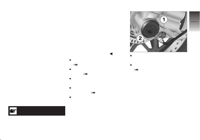
Remove bolt 1 and loosen
wheel speed sensor 2.
Remove brake calipers
( 112).
5
43
z
Setting
Page 46
5
44
z
Setting
CAUTION
Component damage and malfunction of the assistance
systems
Incorrect distance between sensor ring and wheel speed sensor
Left clamp locks the threaded
bush and must not be loosened or removed.
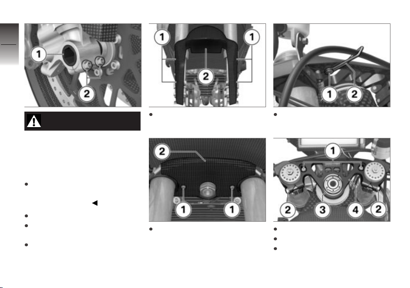
Loosen clamping bolt 2.
Remove quick-release axle 1
while supporting wheel.
Roll front wheel forward to remove it.
Remove screws 1 and front
wheel cover 2.
Remove screws 1 and fork partition 2.
Remove bolt 1 and loosen
bracket 2.
Remove screws 1.
Loosen screws 2.
Remove steering head nut 3.
Page 47
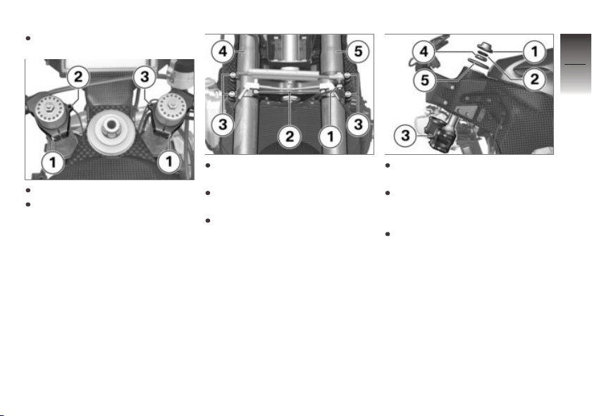
Remove top fork bridge 4.
5
45
Loosen screws 1.
Detach left stub handlebars 2
and right stub handlebars 3
from fork leg and leave to hang
from motorcycle.
Remove bolt 1 with washer
and nut for steering damper.
Remove bolts 2 and lay brake
lines aside.
Loosen bolts 3 and remove
fork leg 4 and 5 downward.
Remove lock nut 1 and rubber
washer 2.
Hold down fork bridge 3 and
remove slotted nut 4 with
cover plate 5.
Pull out fork bridge 3 downward.
z
Setting
Page 48
5
46
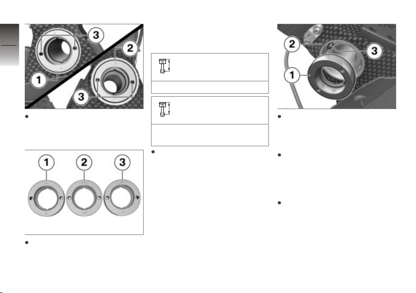
Evenly push out steering-head
z
Setting
bearing at bottom 1 and top 2
using the removal thread 3.
In addition to the steeringhead bearing inserts with 0°
installed by default 1, steeringhead bearing inserts with +/-
0.5° 2 and steering-head bearing inserts with +/- 1° 3 are
also supplied.
Steering head angle basic setting
Steering head angle insert 0°
Steering head angle adjustment range
Steering head angle inserts
+/ 0.5°; 0.0° and +/- 1°
During the installation, make
sure that two identical the
steering-head bearing inserts
are installed at the top and
bottom and that they are
aligned with the markings on
the frame using the same
values.
Align steering-head bearing insert 1 with the desired angular
offset to the marking 2 on the
frame.
Attach the steering-head bearing insert 1 by hand so that the
alignment tool 3 engages in
the bore on the steering-head
bearing insert 1.
Install steering-head bearing insert 1 in the frame with bearing
draw-in set (83 30 0 444 323).
Page 49
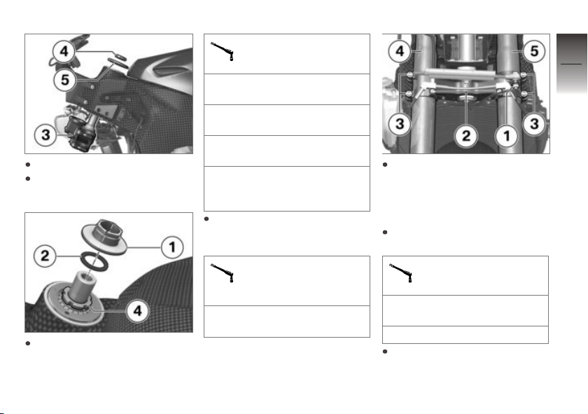
Insert fork bridge 3 from below.
Install slotted nut 4 with cover
plate 5.
Tighten slotted nut 4 according
to adjusting instructions.
Steering-head bearing
adjusting instructions
18 lb/ft (25 Nm) (Tightening
torque)
Swivel fork three times to the
left/right
80° (slacken (fork on left
steering stop))
4 lb/ft (5 Nm) (Tightening
torque (fork on right steering
stop))
Install rubber ring 2 and lock
nut 1 and tighten to specified
torque.
Lock nut for steeringhead bearing adjusting
nut
2 lb/ft (3 Nm) (Tightening
torque)
Install fork legs 4 and 5 and
provisionally tighten bolts 3.
After installing the top fork
bridge, the fork tube overhang
must be adjusted.
Attach brake lines, fit bolts 2
and tighten to specified torque.
Brake line on fork bridge
Joint compound: Lubricate
thread, Optimoly TA
6 lb/ft (8 Nm)
Fit bolt 1 with washer and nut
for steering damper and tighten
to specified torque.
5
47
z
Setting
Page 50
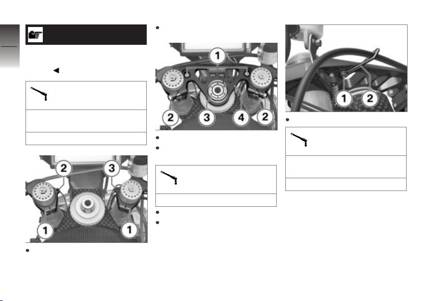
5
48
NOTICE
Washer must be fitted between
steering damper and fork
bridge.
Steering damper on fork
bridge
Provisionally tighten bolts 1.
Thread-locking compound:
Loctite 243, Medium-firm
z
Setting
14 lb/ft (19 Nm)
Install left stub handlebars 2
and right stub handlebars 3 on
fork leg.
Install top fork bridge 4.
Install steering head nut 3 and
tighten to specified torque.
Top fork bridge on head
tube
59 lb/ft (80 Nm)
Do not tighten bolts 2.
Fit bolts 1, but do not tighten
yet.
Attach retainer 2 and fit bolt 1.
Clutch cable holder on
top fork bridge
Joint compound: Lubricate
thread, Optimoly TA
2 lb/ft (3 Nm)
Page 51
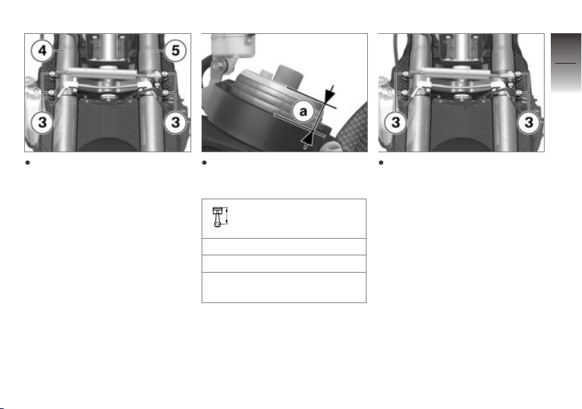
5
49
Loosen bolts 3 on lower fork
bridge and adjust fork tube
overhang on both fork legs 4
and 5.
Adjust desired fork tube overhang dimension a identically on
both fork legs.
Projection of fork tube in
fork bridge, top
with cap
0.6 in (15 mm) (Basic setting)
0.2...1 in (5...25 mm) (Adjustment range)
Tighten screws 3 to appropriate torque.
z
Setting
Page 52
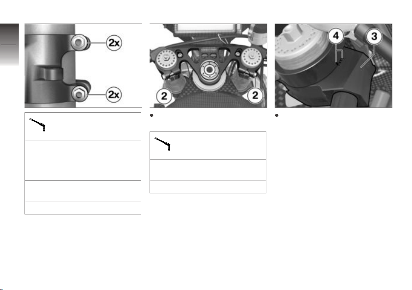
5
50
z
Setting
Bottom fork bridge on
fixed fork tube
Tightening sequence: Tighten
the screws 4 times, alternating
between one and the other
each time
Joint compound: Lubricate
thread, Optimoly TA
10 lb/ft (14 Nm)
Tighten screws 2 to appropriate torque.
Top fork bridge on fixed
fork tube
Joint compound: Lubricate
thread, Optimoly TA
14 lb/ft (19 Nm)
Adjust handlebar clamp 3 in
the area of the markings 4 to
the desired position. Adjust
the left handlebar clamp to the
same position.
Page 53
5
51
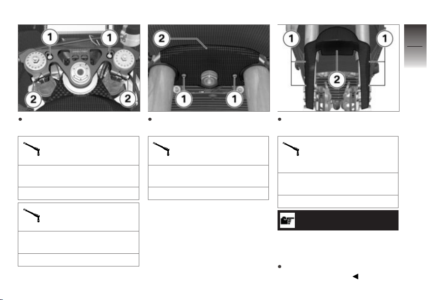
First tighten screws 1 and then
screws 2 to appropriate torque.
Locking screw on top
fork bridge
Joint compound: Lubricate
thread, Optimoly TA
6 lb/ft (8 Nm)
Handlebar clamp on fork
leg
Joint compound: Lubricate
thread, Optimoly TA
14 lb/ft (19 Nm)
Attach fork partition 2 and fit
screws 1.
Fork partition on fork
bridge
Joint compound: Lubricate
thread, Optimoly TA
4 lb/ft (5 Nm)
Attach front wheel cover 2 and
fit bolts 1.
Front wheel cover on
bracket for front wheel
cover
Thread-locking compound:
Loctite 243, Medium-firm
4 lb/ft (5 Nm)
ATTENTION
Front wheel installation opposite the running direction
Accident hazard
Observe running direction arrows on tire or rim.
z
Setting
Page 54
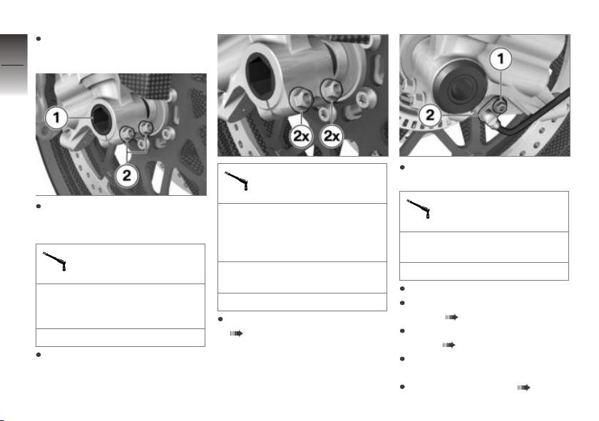
Roll front wheel into front
suspension.
5
52
z
Setting
Lift front wheel and install
quick-release axle 1 with
appropriate torque.
Quick-release axle in
threaded bush
Joint compound: Lubricate
quick-release axle and thread,
Optimoly TA
37 lb/ft (50 Nm)
Tighten clamping bolts 2 to
appropriate torque.
Clamping screw in axle
adapter
Tightening sequence: Tighten
the screws 4 times, alternating
between one and the other
each time
Joint compound: Lubricate
thread, Optimoly TA
14 lb/ft (19 Nm)
Fastening brake caliper
( 113).
Secure wheel speed sensor 2
and fit bolt 1.
Front wheel speed sensor on bracket
Joint compound: Lubricate
thread, Optimoly TA
4 lb/ft (5 Nm)
Remove engine jack.
Install the upper section of the
fairing ( 130).
Install the right fairing side
panel ( 130).
Install left fairing side panel in
the same way.
Install engine spoiler ( 130).
Page 55
Fork bridge offset
Setting
The HP4 Race concept provides the option to adjust the
fork bridge offset to four offsets
using different inserts. Special
tools and additional tools such as
the engine jack or safety stands
on the frame and footrests are
required for this; how to handle these tools is not addressed
further here. If you are not sure
whether this work is within your
skill range, please contact a specialist workshop, preferably a
BMW Motorrad partner.
Adjusting the fork bridge
offset
Remove the engine spoiler
( 128).
Removing right fairing side
panel ( 129).
Remove left fairing side panel
in the same way.
Lift the motorcycle with the engine jack so that the front end
is relieved. Secure the motorcycle against falling over.
Remove front wheel ( 123).
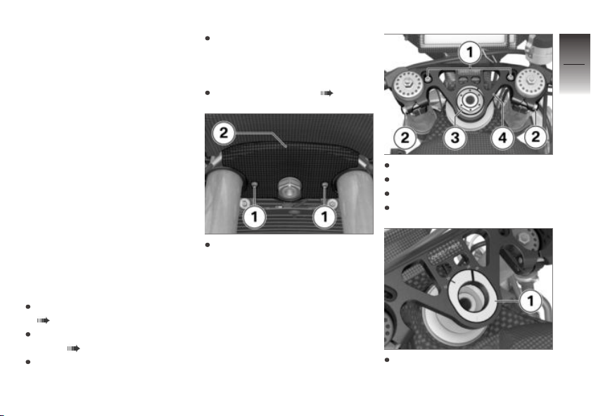
Remove screws 1 and fork partition 2.
Remove screws 1.
Loosen screws 2.
Remove steering head nut 3.
Raise top fork bridge 4.
Remove fork bridge insert 1.
5
53
z
Setting
Page 56
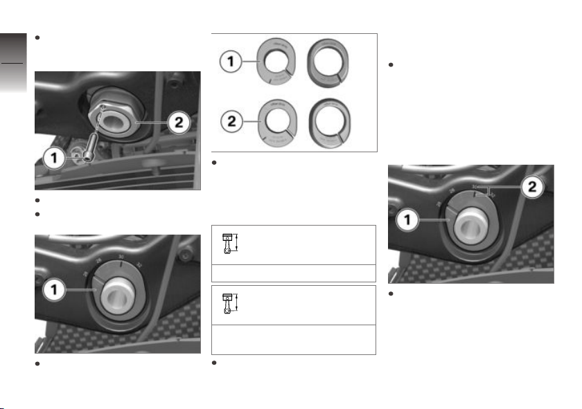
Support front forks using suitable tool.
5
54
z
Setting
Remove retaining screw 1.
Remove nut 2.
Remove fork bridge insert 1.
In addition to the fork bridge
inserts with 28/30 mm 1 installed by default, fork bridge
inserts with 26/32 mm 2 are
also supplied.
Fork bridge offset basic
setting
Fork bridge insert 30 mm
Fork bridge offset adjustment range
Fork bridge inserts 26/32 mm
and 28/30 mm
The fork bridge inserts can be
installed in two positions; this
results in four different fork
bridge offsets.
During the installation, make
sure that the fork bridge inserts
at the top and bottom are both
installed with the same offset;
align them with the markings
on the fork bridge using the
same values.
Install fork bridge insert 1, taking care to align it with the fork
bridge using the marking 2 for
the desired offset.
Page 57
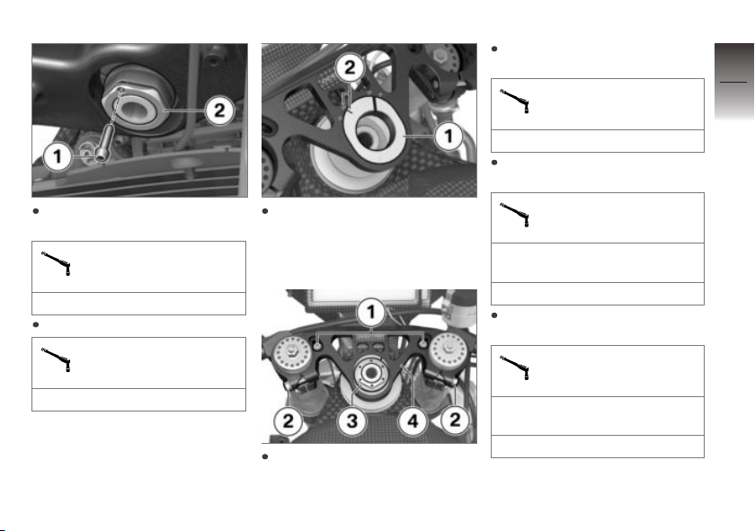
Install nut 2 and tighten to
specified torque.
Lock nut on lower head
tube
44 lb/ft (60 Nm)
Install retaining screw 1.
Retaining screw on lock
nut for lower head tube
2 lb/ft (3 Nm)
Install fork bridge insert 1, taking care to align it with the fork
bridge using the marking 2 for
the desired offset.
Install top fork bridge 4.
Install steering head nut 3 and
tighten to specified torque.
Top fork bridge on head
tube
59 lb/ft (80 Nm)
Tighten screws 2 to appropriate torque.
Top fork bridge on fixed
fork tube
Joint compound: Lubricate
thread, Optimoly TA
14 lb/ft (19 Nm)
Install screws 1 and tighten to
specified torque.
Locking screw on top
fork bridge
Joint compound: Lubricate
thread, Optimoly TA
6 lb/ft (8 Nm)
5
55
z
Setting
Page 58
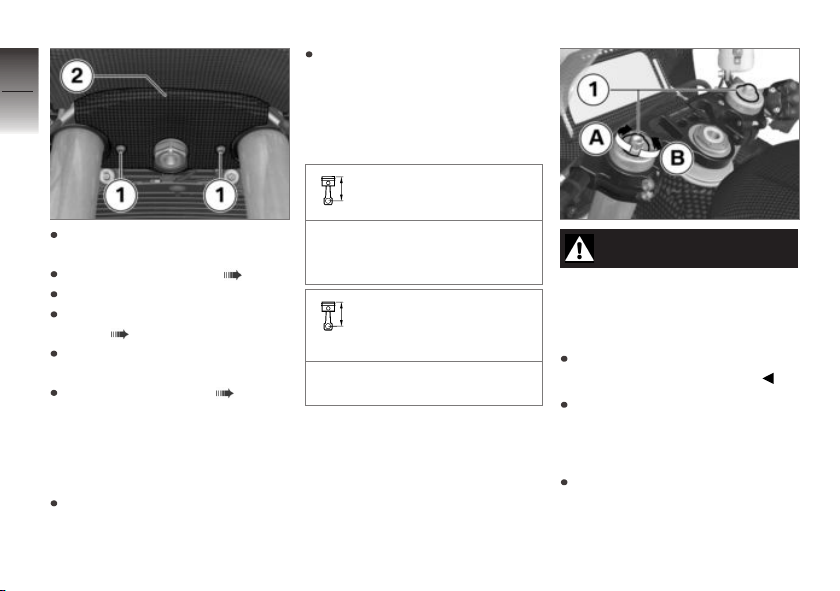
5
56
Adjust the spring preload to
the rider's weight for the basic setting. The data from the
spring travel indicator or data
recording must be used for fine
tuning.
Front forks spring
preload basic setting
Attach fork partition 2 and fit
z
Setting
screws 1.
Install the front wheel ( 124).
Remove engine jack.
Install the right fairing side
panel ( 130).
Install left fairing side panel in
the same way.
Install engine spoiler ( 130).
Spring preload
Adjusting the spring
preload on the front wheel
Park motorcycle, ensuring that
support surface is firm and
level.
Turn adjuster as far as possible anticlockwise, then turn
5 mm (5 revolutions) clockwise
Front forks spring
preload adjustment
range
0...18 mm correspond to
18 revolutions
WARNING
Uncoordinated settings of
spring preload and spring
strut damping.
Poorer handling.
Adjust damping characteristic
to changed spring preload.
To decrease spring deflection
(increase spring preload), turn
adjusting screws 1 in direction A.
To increase spring deflection
(reduce spring preload), turn
adjusting screws 1 in direction B.
Page 59
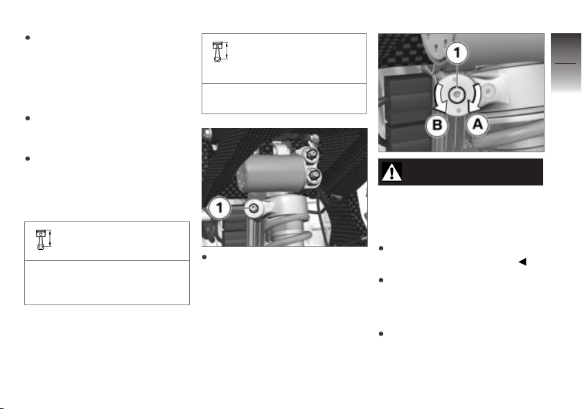
Make sure that the same values are set on the left and
right.
Adjusting the spring
preload on the rear wheel
Park motorcycle, ensuring that
support surface is firm and
level.
Adjust the spring preload to
the rider's weight for the basic
setting. The data from the data
recording must be used for fine
tuning.
Spring strut spring
preload basic setting
Turn adjuster as far as possible anticlockwise, then turn
1 mm (2 revolutions) clockwise
Spring strut spring
preload adjustment
range
0...8.5 mm correspond to
17 revolutions
Adjust spring preload using the
adjusting screw 1.
WARNING
Uncoordinated settings of
spring preload and spring
strut damping.
Poorer handling.
Adjust damping characteristic
to changed spring preload.
To decrease spring compression (increase spring preload),
turn adjusting screw 1 in direction A.
To increase spring compression (reduce spring preload),
turn adjusting screw 1 in direction B.
5
57
z
Setting
Page 60
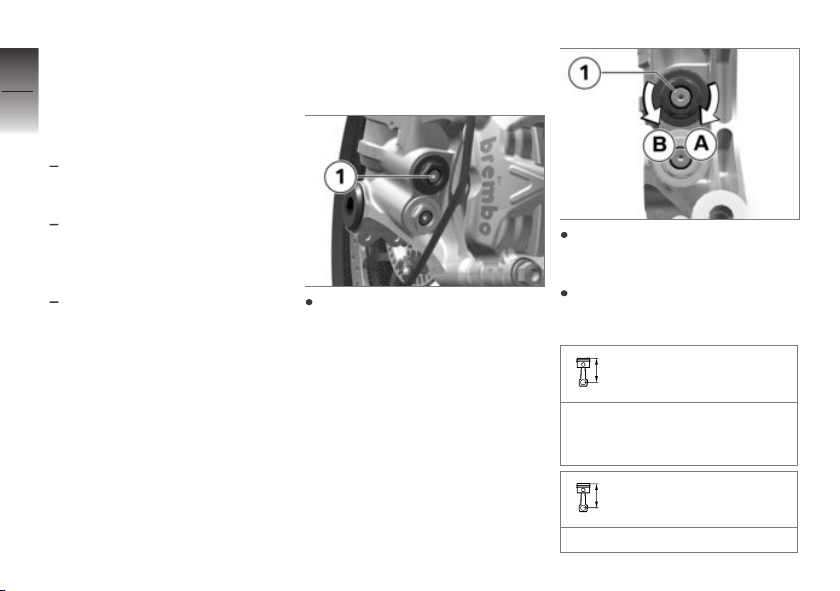
Damping
5
Setting
58
Damping must be adjusted to the
road conditions and the spring
preload.
A rough road surface requires
softer damping than a smooth
road surface.
An increase in spring preload
requires firmer damping, a re-
z
Setting
duction in spring preload requires softer damping.
The damping setting is
counted from completely
closed position (turn adjusting
screw clockwise as far as
possible).
Adjusting the reboundstage damping on front
wheel
Adjust the rebound-stage
damping on the fork base of
both fork legs using the top
adjusting screw 1.
To increase the damping: Turn
adjusting screw 1 in direction A.
To reduce the damping: Turn
adjusting screw 1 in direction B.
Front forks rebound basic setting
Turn adjuster (R) as far as
possible clockwise, then 20
clicks counterclockwise
Front forks rebound adjustment range
1...26 clicks
Page 61
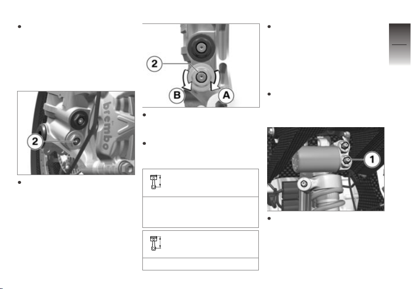
Make sure that the same values are set on the left and
right.
Adjusting the
compression damping on
the front wheel
Adjust the compression damping on the fork base of both
fork legs using the adjusting
screw 2.
To increase the damping: Turn
adjusting screw 2 in direction A.
To reduce the damping: Turn
adjusting screw 2 in direction B.
Front forks compression
stage basic setting
Turn adjuster (C) as far as
possible clockwise, then 20
clicks counterclockwise
Front forks compression
stage adjustment range
1...26 clicks
Make sure that the same values are set on the left and
right.
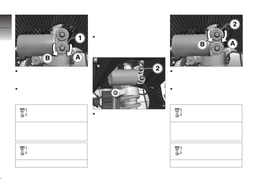
Adjusting the reboundstage damping on the rear
wheel
Park motorcycle, ensuring that
support surface is firm and
level.
Adjust rebound-stage damping with the lower adjusting
screw 1.
5
59
z
Setting
Page 62
5
60
Adjusting the
compression damping on
rear wheel
Park motorcycle, ensuring that
support surface is firm and
level.
To increase the damping: Turn
z
Setting
adjusting screw 1 in direction A.
To reduce the damping: Turn
adjusting screw 1 in direction B.
Spring strut rebound basic setting
Turn adjuster (R) as far as
possible clockwise, then 12
clicks counterclockwise
Spring strut rebound adjustment range
1...26 clicks
Adjust compression damping
with top adjusting screw 2.
To increase the damping: Turn
adjusting screw 2 in direction A.
To reduce the damping: Turn
adjusting screw 2 in direction B.
Spring strut compression
stage basic setting
Turn adjuster (C) as far as
possible clockwise, then 18
clicks counterclockwise
Spring strut compression
stage adjustment range
1...26 clicks
Page 63
Ride height
Setting
When adjusting the ride height,
be aware that the clearance of
various components cannot be
guaranteed for certain setting
combinations. It is therefore
important to always check the
clearance of the steering, front
wheel, rear wheel swinging arm,
and rear wheel after any changes
are made.
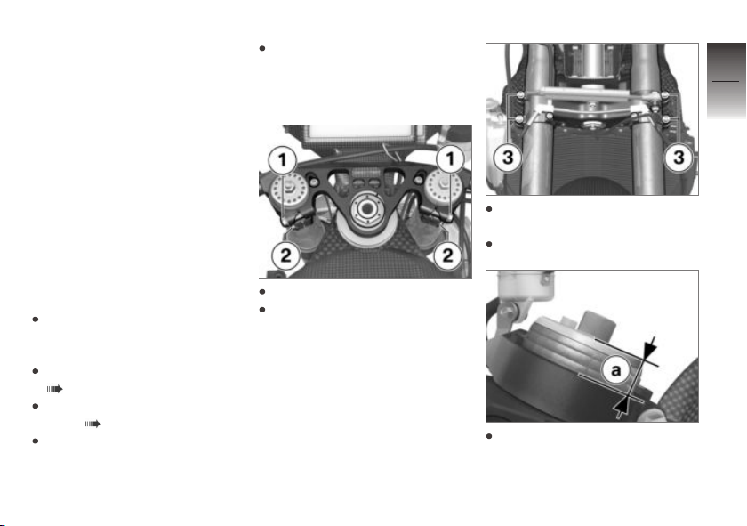
Lift the motorcycle with the engine jack so that the front end
is relieved. Secure the motorcycle against falling over.
Support front forks using suitable tool.
Loosen screws 3.
5
61
z
Setting
Adjusting the front ride
height
Park motorcycle, ensuring that
support surface is firm and
level.
Remove the engine spoiler
( 128).
Removing right fairing side
panel ( 129).
Remove left fairing side panel
in the same way.
Loosen screws 1.
Loosen screws 2.
Set fork tube overhang (equivalent to the ride height) a to the
desired value.
Page 64
5
62
z
Setting
Projection of fork tube in
fork bridge, top
with cap
0.6 in (15 mm) (Basic setting)
0.2...1 in (5...25 mm) (Adjustment range)
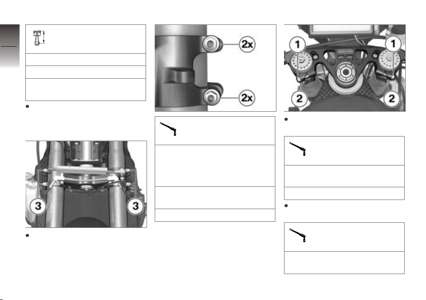
Make sure that the fork tube
overhang is the same on both
fork legs.
Tighten screws 3 to appropriate torque.
Bottom fork bridge on
fixed fork tube
Tightening sequence: Tighten
the screws 4 times, alternating
between one and the other
each time
Joint compound: Lubricate
thread, Optimoly TA
10 lb/ft (14 Nm)
Tighten screws 1 to appropriate torque.
Top fork bridge on fixed
fork tube
Joint compound: Lubricate
thread, Optimoly TA
14 lb/ft (19 Nm)
Tighten screws 2 to appropriate torque.
Handlebar clamp on fork
leg
Joint compound: Lubricate
thread, Optimoly TA
Page 65
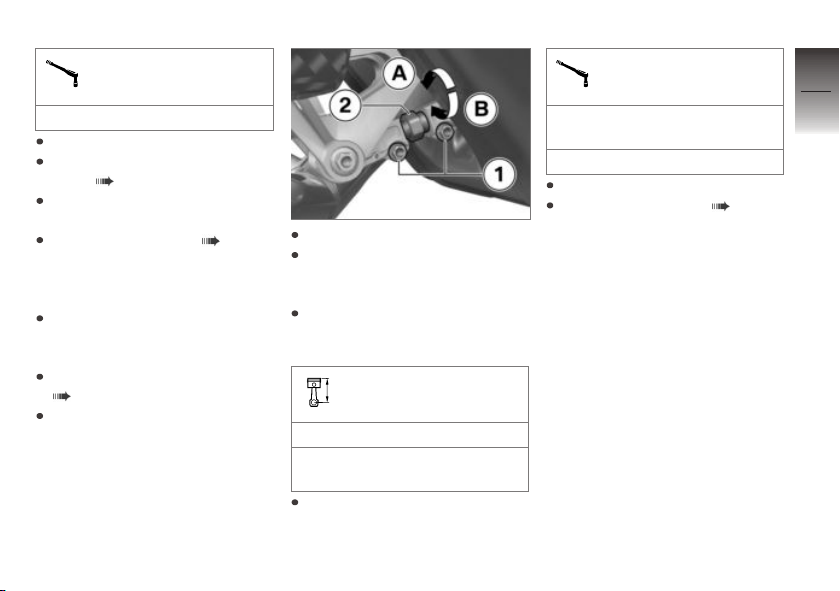
Handlebar clamp on fork
leg
14 lb/ft (19 Nm)
Remove engine jack.
Install the right fairing side
panel ( 130).
Install left fairing side panel in
the same way.
Install engine spoiler ( 130).
Adjusting the rear ride
height at the tension strut
Park motorcycle, ensuring that
support surface is firm and
level.
Remove the engine spoiler
( 128).
Lift the motorcycle with the
engine jack so that the rear
wheel swinging arm is relieved.
Secure the motorcycle against
falling over.
Loosen clamping bolt 1.
To increase the ride height:
Turn the adjusting screw 2 in
direction A.
To reduce the ride height:
Turn the adjusting screw 2 in
direction B.
Tension strut length
4.4 in (113 mm) (Basic setting)
4.3...4.6 in (108...118 mm)
(Adjustment range)
Tighten clamping bolts 1.
Clamping bolt on tension
strut
Joint compound: Lubricate
thread, Optimoly TA
7 lb/ft (10 Nm)
Remove engine jack.
Install engine spoiler ( 130).
Rear ride height (RideHeight)
The ride height at the rear-wheel
guide can be adjusted using the
following parameters: swinging arm pivot point, top spring
strut attachment position and
tension strut length. The ride
height of the motorcycle is precisely adjusted by setting the
tension strut length before delivery to the customer. The tension
strut length may therefore differ
slightly from the nominal dimension of 113 mm.
5
63
z
Setting
Page 66
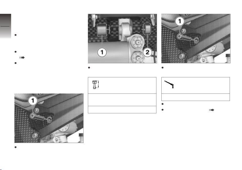
Adjusting the rear ride
5
height at the spring strut
attachment point
64
Park motorcycle, ensuring that
support surface is firm and
level.
Remove the engine spoiler
( 128).
Lift the motorcycle with the
engine jack so that the rear
z
Setting
wheel swinging arm is relieved.
Secure the motorcycle against
falling over.
Remove sliding blocks 1 and 2
and install in inverted position.
Rear vehicle height
Fit bolt 1 and tighten to specified torque.
Spring strut on main
frame
Remove the screw 1.
0 mm (lower eye) (Basic setting)
0/-3 mm (Adjustment range)
41 lb/ft (56 Nm)
Remove engine jack.
Install engine spoiler ( 130).
Page 67
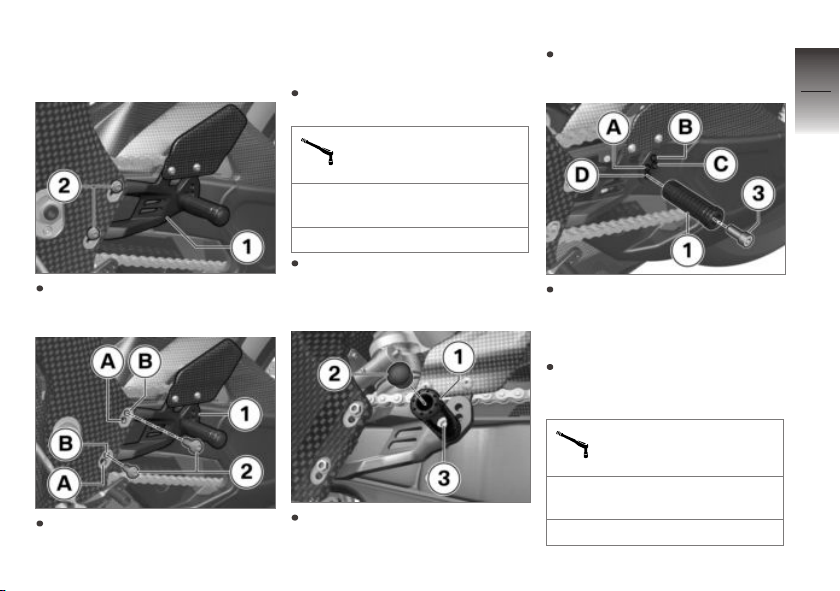
Footrests
Adjusting the footrests
To adjust the footrest plate 1,
remove the bolts 2.
Attach footrest plate 1 in desired position. Footrest plate 1
can be installed in two positions A or B.
Fit bolts 2 and tighten to specified torque.
Driver's footrest bracket
on main frame
Joint compound: Lubricate
thread, Optimoly TA
14 lb/ft (19 Nm)
On the right-hand side, adjust
the footrest plate in the same
way.
To adjust the footrest 1, remove the protective cap 2.
Remove bolt 3 and take out
footrest 1.
Attach footrest 1 in desired
position. Footrest 1 can be installed in four positions A, B, C
or D.
Fit bolt 3 and tighten to specified torque, making sure to
brace footrest 1.
Footrest on footrest
plate
Thread-locking compound:
Loctite 243, Medium-firm
18 lb/ft (25 Nm)
5
65
z
Setting
Page 68
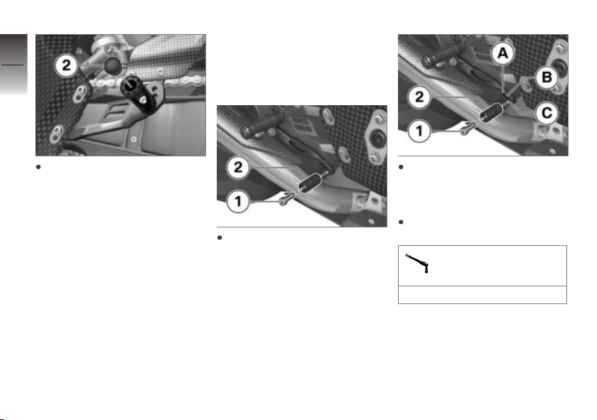
5
66
Foot piece for footbrake lever
Adjusting the foot piece
on the footbrake lever
Install protective cap 2.
z
Setting
Remove bolt 1 and foot
piece 2.
Attach foot piece 2 in desired
position. Foot piece 2 can be
install in three positions A, B
or C.
Fit bolt 1 and tighten to specified torque.
Foot piece on footbrake
lever
7 lb/ft (10 Nm)
Page 69
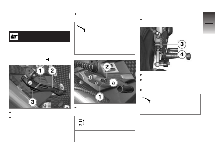
Footbrake lever height
Adjusting the footbrake
lever height
NOTICE
After adjusting the footbrake
lever, the free travel of the
pushrod must be adjusted on the
brake pedal cylinder.
Loosen the screw 1.
Press down footbrake lever 2
and turn eccentric 3 until desired footbrake lever 2 height is
reached.
Tighten bolt 1, making sure to
brace eccentric 3.
Eccentric height adjustment on brake lever
Joint compound: Lubricate
thread, Optimoly TA
4 lb/ft (5 Nm)
Check blow-by clearance a between eccentric 1 and stop 2.
Blow-by clearance of
footbrake lever
0.08 in (2 mm) (between eccentric and stop)
Blow-by clearance not correct
Adjust blow-by clearance.
Loosen nut 3 on pushrod 4.
Twist pushrod 4 until play on
brake lever is correct.
Counter nut 3 on pushrod 4.
Pushrod on brake pedal
cylinder
4 lb/ft (6 Nm)
5
67
z
Setting
Page 70
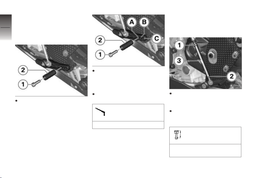
Foot piece for gearshift
5
lever
68
Adjusting the foot piece
on the gearshift lever
Gearshift lever height
Adjusting the gearshift
lever height
z
Setting
Remove bolt 1 and foot
piece 2.
Attach foot piece 2 in desired
position. Foot piece 2 can be
install in three positions A, B
or C.
Fit bolt 1 and tighten to specified torque.
Foot piece on gearshift
lever
7 lb/ft (10 Nm)
Loosen nuts 1 and 2, making sure to brace on gearshift
rod 3.
Turn gearshift rod 3 until the
gearshift lever has reached the
desired height.
Gearshift rod length
Distance between both steering head axles
Page 71
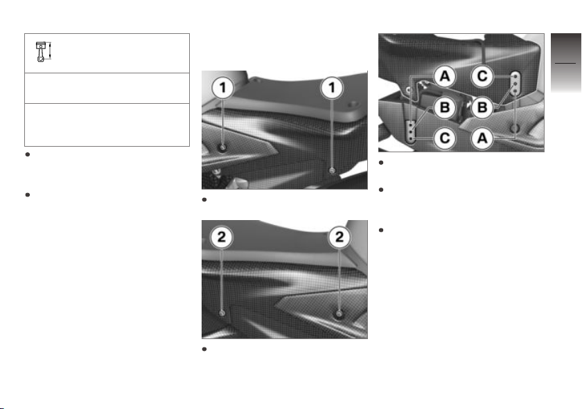
Gearshift rod length
10.3 in (260.8 mm) (Delivery
status)
10.3...10.7 in
(260.8...272.8 mm)
(Adjustment range)
Tighten nuts 1 and 2, taking
care to counter on the gearshift
rod 3.
Make sure that joints are not
stressed on tightening.
Seat height
Adjusting the seat height
Remove screws 1.
Remove screws 2.
The tail section can be installed
in the position A, B or C.
When doing so, make sure that
the same height is set at the
front and rear.
Position A is the delivery status.
5
69
z
Setting
Page 72
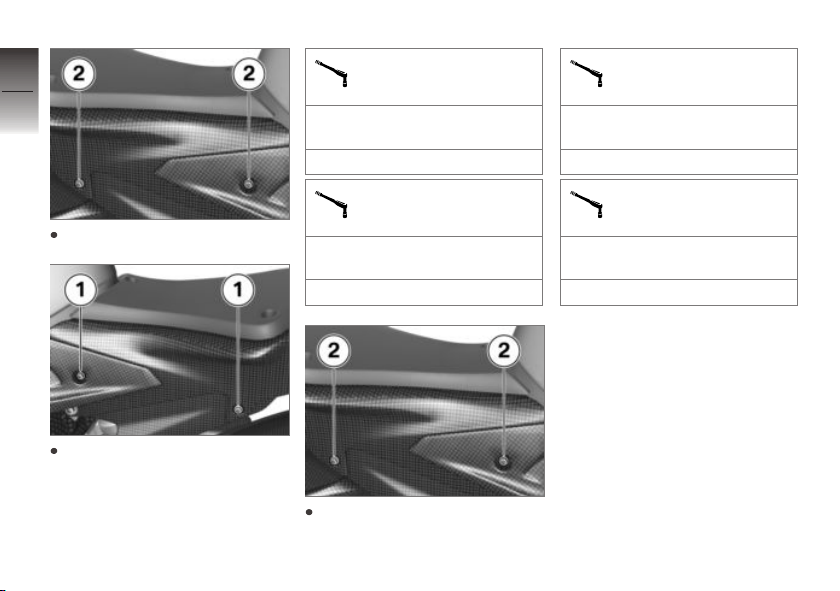
5
70
Fit bolts 2, do not tighten.
z
Setting
Fit and tighten bolts 1.
Tail section with tank
cover on rear frame
Thread-locking compound:
Loctite 243, Medium-firm
6 lb/ft (8 Nm)
Tail section on rear
frame
Thread-locking compound:
Loctite 243, Medium-firm
6 lb/ft (8 Nm)
Tighten screws 2.
Tail section with tank
cover on rear frame
Thread-locking compound:
Loctite 243, Medium-firm
6 lb/ft (8 Nm)
Tail section on rear
frame
Thread-locking compound:
Loctite 243, Medium-firm
6 lb/ft (8 Nm)
Swinging arm
Setting
The HP4 Race concept provides
the option to adjust the swinging
arm pivot point to various positions. Additional tools such as
the engine jack or footrest stands
are required for this; how to handle these tools is not addressed
further here. If you are not sure
whether this work is within your
Page 73
skill range, please contact a specialist workshop, preferably a
BMW Motorrad partner.
Setting the swing arm
pivot point
Park motorcycle, ensuring that
support surface is firm and
level.
Remove the engine spoiler
( 128).
Raise the motorcycle using an
engine jack or another suitable jack so that the rear wheel
swinging arm is relieved.
Support the rear wheel swinging arm before removing the
swing axle and secure against
falling over.
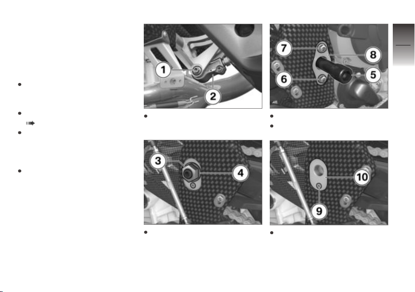
Remove bolt 1 and loosen
pivot strut 2.
Remove swing axle 5.
Remove bolts 6 and 7 insert 8.
5
71
z
Setting
Remove nut 3 and washer 4.
Remove bolt 9 and insert 10.
Page 74
5
72
stalled with the same offset.
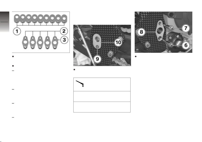
Select desired inserts for left 1
z
Setting
and right 2.
Here it is important to note:
The inserts for the right-hand
side can be installed in two positions. The offset is specified
with + or - on the insert.
The offset specification 3,
which can be read above the
swing axle, is the valid value.
The inserts for the left-hand
side can only be installed in
one position.
The inserts for the left and
right must always be in-
Install desired insert 10 and
bolt 9.
Left swinging arm bearing insert on frame
Thread-locking compound:
Loctite 243, Medium-firm
4 lb/ft (5 Nm) (Countersunk
screw)
When fitting the bolts 6 and 7,
note that the bolt 6 with a
countersunk cone needs to be
fitted in the countersunk bore
of the insert 8.
Page 75
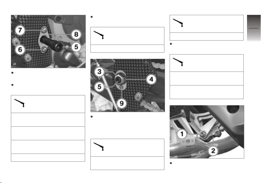
Install desired insert 8 and fit
bolt 6 so that it is hand-tight.
Fit bolt 7 and tighten both
bolts with specified torque.
Right swinging arm bearing insert on frame
Install swing axle 5 and tighten
to specified torque.
Swing axle on frame
7 lb/ft (10 Nm)
Nut on swing axle
74 lb/ft (100 Nm)
Tighten screw 9 to specified
torque.
Left swinging arm bearing insert on frame
Thread-locking compound:
Loctite 243, Medium-firm
4 lb/ft (5 Nm) (Countersunk
screw)
5
73
z
Setting
Joint compound: Lubricate
thread, Optimoly TA
28 lb/ft (38 Nm) (with countersunk taper)
Joint compound: Lubricate
thread, Optimoly TA
28 lb/ft (38 Nm) (with collar)
Install nut 3 with washer 4 and
tighten to specified torque,
making sure to brace swing
axle 5.
Nut on swing axle
Thread-locking compound:
mechanical
Attach pivot strut 2, fit bolt 1
and tighten to specified torque.
Page 76

5
74
z
Setting
Pivot strut on relay lever
Joint compound: Lubricate
thread, Optimoly TA
28 lb/ft (38 Nm)
Remove engine jack.
Install engine spoiler ( 130).
Page 77

Riding
Safety information . . . . . .. . . . . . .. . . . . 76
Checklist. . . . . .. . . . . . .. . . . . .. . . . . . .. . 77
Starting . . . . .. . . . . . . . . . . . .. . . . . . .. . . . 77
Bringing the engine up to operating
temperature . . . . . . . . . . . .. . . . . . . . . . . . 79
Running in . . . . . . . . . . .. . . . . . . . . . . . .. . 79
Shifting gears . . . . .. . . . . . .. . . . . . . . . . . 80
Brakes . . . . . . .. . . . . .. . . . . . .. . . . . .. . . . 81
Start of race . . . . . . . . . . .. . . . . . . . . . . . . 82
Speed limiter for pit lane . . . . . .. . . . . . 84
Parking your motorcycle . . . .. . . . . . .. 84
6
75
z
Riding
Page 78
Safety information
6
M Sport is dangerous
76
BMW Motorrad wants you to
have a great time with your motorcycle. That's why you should
be aware that the HP4 Race is
a very special motorcycle whose
unique purpose is for racing. Engine power at superbike world
championship level and a weight
z
Riding
close to that of a MotoGP motorcycle creates extraordinary driving
dynamics that are not comparable with a road-approved motorcycle. This requires a calm
riding style, particularly in the initial turns. Gradually get used to
the ride feeling, throttle response,
control characteristics of the assistance systems, engine power
and braking response. Familiarize yourself with the racing sport
features. Read this rider's manual and observe the warnings and
notes.
Rider's Equipment
Never ride without wearing the
right clothing! Always wear:
Helmet
Leather combination suit
Back protector
Gloves
Boots
This applies throughout the
whole year. Your authorized
BMW Motorrad retailer will be
happy to advise you and has
the correct clothing for every
purpose.
Speed
While riding at high speeds on
the racing track, always bear in
mind that various boundary conditions can adversely affect the
handling of your motorcycle:
Settings of spring-strut and
shock absorber system
incorrect tire pressure
worn racing tires
temperature and condition of
the road
Etc.
Risk of poisoning
Exhaust fumes contain carbon
monoxide, which is colorless and
odorless but highly toxic.
WARNING
Harmful exhaust gas
Danger of suffocation
Do not inhale exhaust fumes.
Do not run the engine in
closed rooms.
Page 79
Burn hazard
CAUTION
Intense heating up of engine
and exhaust system while
riding
Burn hazard
After parking the motorcycle,
make sure that no persons
or objects come into contact
with the engine and exhaust
system.
Danger of overheating
ATTENTION
Engine running for an extended period while stationary
Overheating caused by insufficient cooling, vehicle fire in extreme cases
Do not allow the engine to idle
unnecessarily.
Drive off after reaching the operating temperature, or turn off
the engine again.
Outside temperatures
Do not drive the motorcycle outside of the specified temperature
range.
Recommended outsidetemperature range
41...104 °F (5...40 °C)
Modifications
ATTENTION
Modifications to the motorcycle (e.g. engine control
unit, throttle valves, clutch)
Damage to the affected parts,
failure of safety-relevant functions, expiration of warranty
Do not make any
modifications.
Checklist
Observe checklist
Use the following checklist to
check your motorcycle at regular intervals.
Before every journey:
Check tire pressure and tire
condition.
Check operation of the brake
system.
Checking clutch function
( 121).
Check function and free movement of the steering damper
and the steering.
Check settings of DTC, EBR
and riding mode.
Starting
Starting engine
Switch on the ignition.
6
77
z
Riding
Page 80
6
78
z
Riding
ATTENTION
Component damage
Starting the engine with gear engaged
The motorcycle is not
equipped with engine starting
suppression. Always engage
neutral gear when starting or
pull the clutch.
Engage neutral, or pull back
clutch lever if a gear is engaged.
In the case of cold start or under cold temperatures: Pull
back clutch lever.
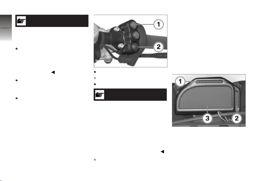
Press KILL button 1.
Button engages.
Press START button 2.
NOTICE
The starting attempt is automatically interrupted if battery voltage
is too low. Recharge the battery
before you attempt to start the
engine again, or use jumper cables and a donor battery to start.
More detailed information can
be found in the "Maintenance"
chapter under "Jump-starting".
Engine starts.
Pre-Ride-Check
After the ignition is switched on,
the instrument panel performs a
Pre-Ride-Check test to check the
warning lights and the tachometer. Only start the engine if the
Pre-Ride-Check has been completed.
Phase 1
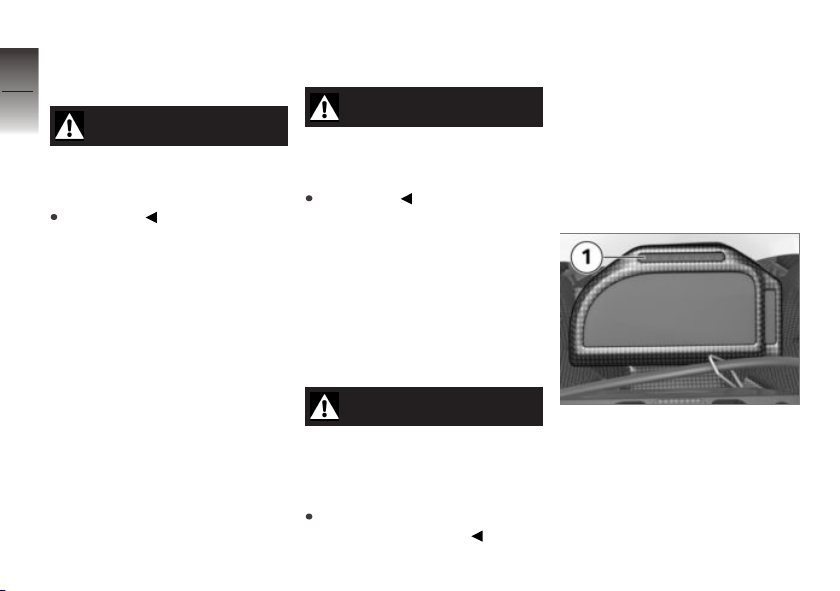
The LED band 1 lights up from
left to right.
The warning and indicator lights
2 light up from top to bottom.
The start screen appears in the
multifunction display 3.
Page 81

Phase 2
The LED and the warning and
indicator lights are unlit; the
mechatronics technician page 1
is displayed in the multifunction
display.
Should one of the warning lights
fail to appear:
WARNING
Defective warning lights
Lack of display of malfunctions
Check the display of all indicator and warning lights.
Have the malfunction corrected
as soon as possible at an
authorized service facility,
preferably an authorized
BMW Motorrad Retailer.
Bringing the engine up to operating temperature
It is very important that the engine and its operating fluids are
at the right temperature before
you start riding on the racing
track.
Therefore warm up the coolant
and engine oil according to the
following procedure:
Run engine in neutral until the
coolant temperature reaches
90 °C.
Turn off and engine and wait
for 10 minutes.
Start engine again and run
until the coolant temperature
reaches 90 °C again.
You motorcycle is now completely warmed up and ready for
use.
Running in
Engine
The HP4 Race engine is
broken-in ex-works and can be
fully loaded immediately within
the intended temperature
limits.
Brake discs
New brake discs need to be broken in so that they can achieve
their optimum performance and
to avoid damage caused by distortion.
If possible, use used brake pads
to break-in the brake discs. Ride
4-5 laps and brake softly at an
average speed. Avoid any kind
of thermal peak load. After completing the breaking-in laps, park
the motorcycle in the pit and
allow the brakes to cool down
completely without using any
tools.
Do not brake while accelerating
the motorcycle. This can lead to
6
79
z
Riding
Page 82
a sudden increase in temperature
that impairs the brake discs' co-
6
efficient of friction.
80
WARNING
New brake discs
Extension of the braking distance,
risk of accident
Brake early.
z
Riding
Brake pads
New brake pads must be run in
before they achieve their optimum friction force.
If possible, use used brake discs
to break-in the brake pads. Ride
2-3 laps and brake softly at an
average speed. Avoid any kind of
thermal peak load.
If new brake pads and new brake
discs need to be broken in at the
same time, perform the breakingin procedure particularly carefully.
Do not brake while accelerating
the motorcycle. This can lead to
a sudden increase in temperature
that impairs the brake pads' coefficient of friction.
WARNING
New brake pads
Extension of the braking distance,
accident hazard
Brake early.
Tires
New tires have a smooth surface. This must be roughened by
riding in a restrained manner at
various lean angles until the tires
are run in. This running in procedure is essential if the tires are to
achieve maximum grip.
WARNING
Loss of adhesion of new tires
on wet roads and at extreme
angles
Accident hazard
Always think well ahead and
avoid extreme angles.
The tires must always be preheated using tire heaters. This
helps to reduce the risk of accident due to cold tires and also
increase the service life of the
tires.
Shifting gears
Shiftpoint light
While driving, the LED band 1
indicates the speed at which the
rider should shift up to the nexthighest gear.
Page 83
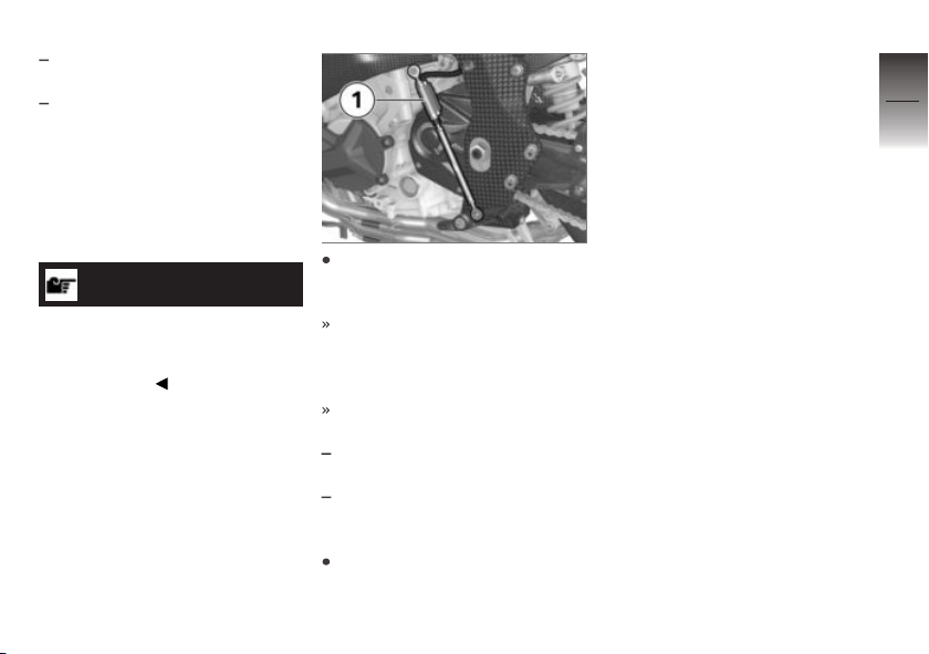
LEDs light up: Switching
speed will soon be reached.
LED band flashes: Switching
speed reached.
The speed thresholds of the
LEDs can be adjusted using the
2D software.
HP Pro gearshift assistant
NOTICE
More detailed information on
HP Pro Gear-shift Assistance can
be found in the "Technology in
detail" chapter.
The gears are shifted into as
usual with foot force on the
shift lever.
The sensor 1 on the gear-shift
rod detects the intention to
change gear and initiates gearshift assistance.
No shifting support is provided
in the following situations:
If the gear lever is not in the
zero position
When upshifting with the throttle valve closed (overrun mode)
or when decelerating
To be able to make another
gear shift using gear-shift assistance, the gear lever must
be fully released after the first
gear change.
Brakes
How do you achieve
the shortest stopping
distances?
The dynamic load distribution between the front and rear wheel
changes during braking. The
heavier you brake, the greater
the weight transfer to the front
wheel. Increases in the load on
an individual wheel are accompanied by a rise in the effective
braking force that the wheel can
provide.
To achieve the shortest possible braking distance, the front
brake must be applied quickly
and with progressively greater
levels of force. This procedure
provides ideal exploitation of the
extra weight transfer to the front
wheel.
6
81
z
Riding
Page 84
The adjustable electronically controlled engine brake EBR stabi-
6
lizes the motorcycle when brak-
82
ing.
Wet, soiled brakes
Moisture and dirt on the brake
rotors and the brake pads result
in a decrease in the braking action.
z
Riding
Delayed or poorer braking action
must be expected in the following situations:
When driving in the rain and
through puddles.
After washing the vehicle.
After working on the brakes
due to oil or grease residues.
During riding on dirty roads.
WARNING
Poorer braking action due to
moisture and dirt
Accident hazard
Brake until brakes are dry or
clean; clean if necessary.
Brake early until the full braking
action is available again.
Start of race
Launch Control
Launch Control supports the
rider in maintaining the ideal
speed for a race start. Launch
Control is activated each time the
motorcycle comes to a standstill;
this thus ensures that the rider is
not distracted before the start of
the race, and that Launch Control
is available.
Engine speed after the
activation of Launch
Control at full throttle
9000 min
When Launch Control is active,
the engine torque is reduced so
that the maximum propulsion on
level ground is set with the front
-1
wheel slightly lifting off. If the
front wheel is detected as lifting off, the torque is temporarily
slightly reduced. The speed limiter is deactivated if one of the
conditions below is reached.
Conditions for deactivating engine speed limita-
tion for Launch Control
Approx. 112 mph (Approx.
180 km/h)
3rd gear is engaged.
Inclined position exceeds 30°
Launch Control is switched off
under the following conditions:
Third gear is engaged.
The speed exceeds 110 mph
(180 km/h).
The inclined position exceeds
30°.
Page 85
Race start with Launch
Control
CAUTION
Risk of accident due to incorrect handling of Launch
Control.
If engaged too quickly, there is
a risk of the engine stalling or
the front wheel abruptly lifting
despite Wheely Control
Engage carefully when starting
race with Launch Control.
NOTICE
Starting the race with Launch
Control causes increased clutch
wear.
Let the clutch cool down after
race start.
The number of race starts possible with Launch Control in quick
succession is limited to three.
Launch Control is activated
by turning on the ignition and
starting the engine. If the engine is running, Launch Control
automatically starts after stopping.
Bring motorcycle in start position.
Vehicle is stationary, engine
is running, Launch Control is
activated.
!LAUNCH! is displayed in the
multifunction display; LEDs
flash.
Proceed as usual when starting, twist throttle grip com-
pletely open, the normally
closed contact keep the speed
at the previously set value.
Engage as quickly as possible,
but still smoothly.
Launch Control controls the
ideal torque on the rear wheel
and keeps the engine speed
constant up to the speed specified below.
Leave throttle grip completely
open.
Due to the full-throttle position
of the throttle grip, the engine
speed increases, as soon as
speed limiting is deactivated.
The throttle grip reacts again
as usual.
Depending on the race track,
upshift and drive around curves
in the inclined position.
If third gear is engaged, the
speeds rises above 110 mph
(180 km/h) or an inclined
position of more than 30° is
achieved, the Launch Control
switches off.
The race start is completed
with Launch Control.
6
83
z
Riding
Page 86
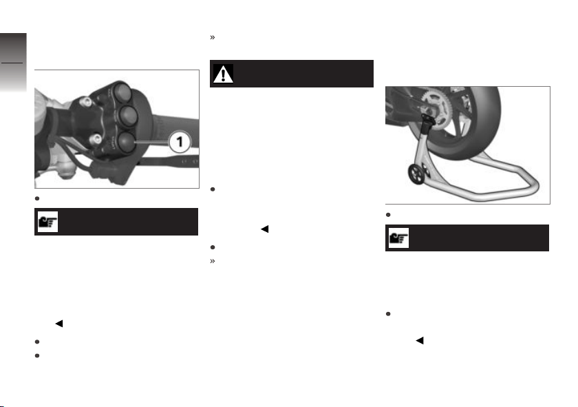
Speed limiter for pit
6
lane
84
z
Riding
Ride in 1st gear.
NOTICE
The maximum speed can be adjusted using the Race Calibration
Kit Pro.
The speed resulting from the
maximum engine speed depends
on the gear ratio and the tire
size.
Hold down starter button 1.
Twist throttle grip open until
cutoff speed is reached.
The engine speed is limited
with ignition interruption.
WARNING
When the starter button is
released, the engine accelerates according to the position of the throttle grip.
Risk of accident by violent jerk
with throttle grip in full load position.
Do not open the throttle
grip completely, but instead
only until the limit speed is
reached.
Release starter button 1.
The vehicle accelerates in line
with the throttle position.
Parking your motorcycle
Rear-wheel stand
Switch off engine.
ATTENTION
Poor ground conditions in
area of stand
Component damage cause by
tipping over
Always check that the ground
under the stand is level and
firm.
Page 87

Attach rear-wheel stand to motorcycle and turn off motorcycle.
Mount the rear-wheel stand
( 106).
6
85
z
Riding
Page 88

6
86
z
Riding
Page 89

In the pit
Refueling . . . . . . . . . .. . . . . . . . . . . . .. . . . 88
Displays for the mechatronics tech-
nician . . . . . . .. . . . . .. . . . . . .. . . . . . . . . . . 90
Displays for the mechatronics tech-
nician . . . . . . .. . . . . .. . . . . . .. . . . . . . . . . . 92
DTC . . . . . . .. . . . . .. . . . . . .. . . . . . . . . . . . 93
EBR . . . .. . . . . . . . . . . . .. . . . . . .. . . . . .. . 93
Gearshift-pattern reverser . . . .. . . . . .. 94
Data recording and 2D software . . .. 95
HP Race Calibration Kit Pro . .. . . . . .. 96
Connector for optional acces-
sories . . . . . .. . . . . . .. . . . . . . . . . . . .. . . . . 96
Securing motorcycle for trans-
port . . . . . .. . . . . .. . . . . . .. . . . . .. . . . . . .. 96
7
87
z
In the pit
Page 90
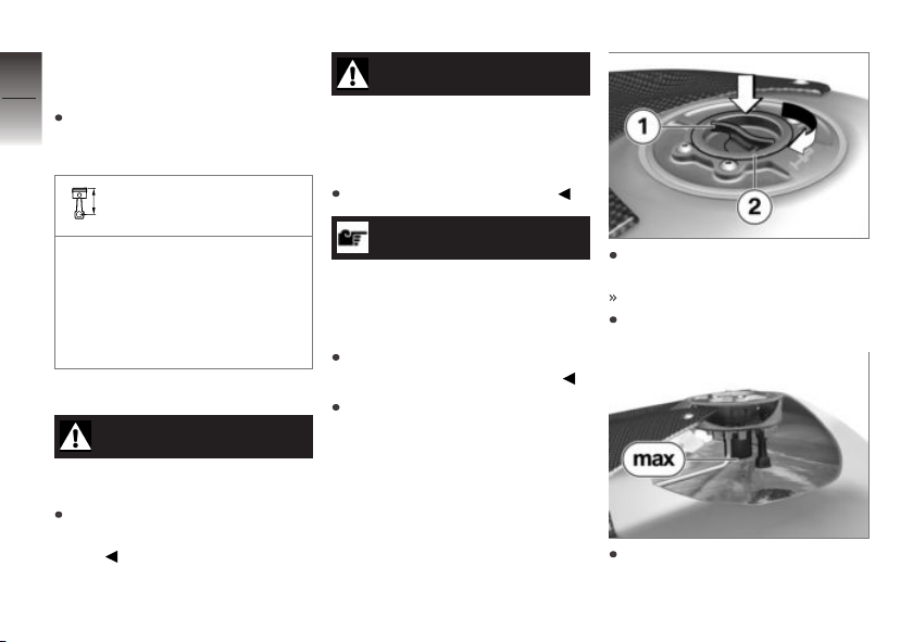
Refueling
7
Fuel specifications
88
Gasoline must be refueled with
the recommended fuel grade in
order to avoid engine damage.
Recommended fuel quality
Gasoline according to
DIN EN 228 (max 5 %
ethanol)
z
In the pit
min 91 AKI (min 98 ROZ/
RON)
min 93 AKI
Refueling
WARNING
Fuel is highly flammable
Fire and explosion hazard
Do not smoke. Never bring
a naked flame near the fuel
tank.
WARNING
Escaping of fuel due to expansion under exposure to
heat with overfilled fuel tank
Accident hazard
Do not overfill the fuel tank.
ATTENTION
Contact of fuel and plastic
surfaces
Damage to surfaces (become
unattractive or cloudy)
Immediately clean plastic surfaces after contact with fuel.
Park motorcycle, ensuring that
support surface is firm and
level.
Press locking mechanism 1
and rotate clockwise.
Fuel filler cap is unlocked.
Remove fuel filler cap 2.
Refuel with a fuel meeting the
specifications above, continu-
Page 91
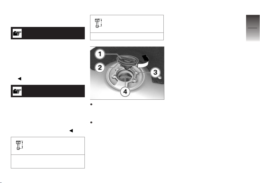
ing until fuel is no higher than
lower edge of filler neck.
NOTICE
When refueling after running on
fuel reserve, the resulting total
fuel quantity must be greater
than the fuel reserve, so that the
new filling level is detected and
the fuel warning light is switched
off.
NOTICE
The "usable fuel quantity" specified in the technical data is the
fuel quantity, which can be refueled if the fuel tank was completely emptied, i.e., if the engine
dies off due to lack of fuel.
Usable fuel quantity
Approx. 4.6 gal (Approx.
17.5 l)
Fuel reserve
Approx. 1.1 gal (Approx. 4 l)
Install fuel filler cap 2 so that
bolts 3 can be inserted through
recesses 4.
Rotate locking mechanism 1
counterclockwise until the fuel
filler cap audibly engages.
7
89
z
In the pit
Page 92
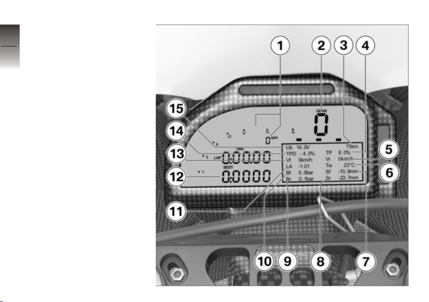
Displays for the
7
mechatronics
90
technician
Multifunction display
mechatronics technician
view 1
1 Tachometer
2 Gear indicator
3 Odometer
4 Throttle valve opening an-
z
In the pit
gle
5 Rear wheel speed
6 Coolant temperature
7 Front spring travel (with
mounted sensor)
8 Rear spring travel (with
mounted sensor)
9 Rear brake pressure (with
mounted sensor)
10 Front brake pressure (with
mounted sensor)
11 Inclined position
12 Best lap time
13 Front wheel speed
Page 93

14 Throttle grip opening angle
15 Battery voltage
7
91
z
In the pit
Page 94
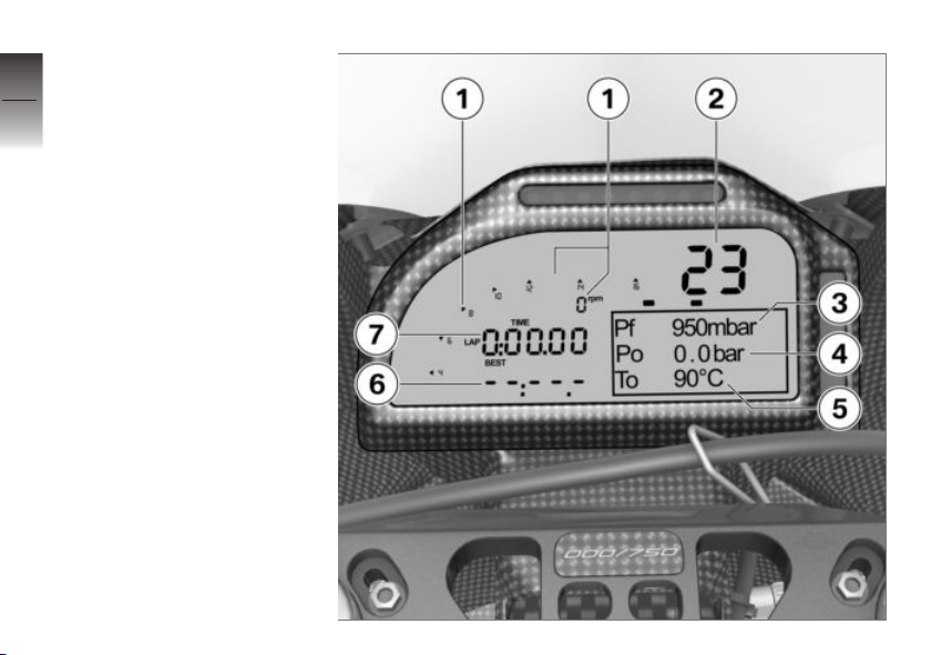
Displays for the
7
mechatronics
92
technician
Multifunction display
mechatronics technician
view 2
1 Tachometer
2 Coolant temperature
3 Fuel pressure
4 Oil pressure (with mounted
z
In the pit
sensor)
5 Oil temperature
6 Best lap time
7 Previous lap time
Page 95
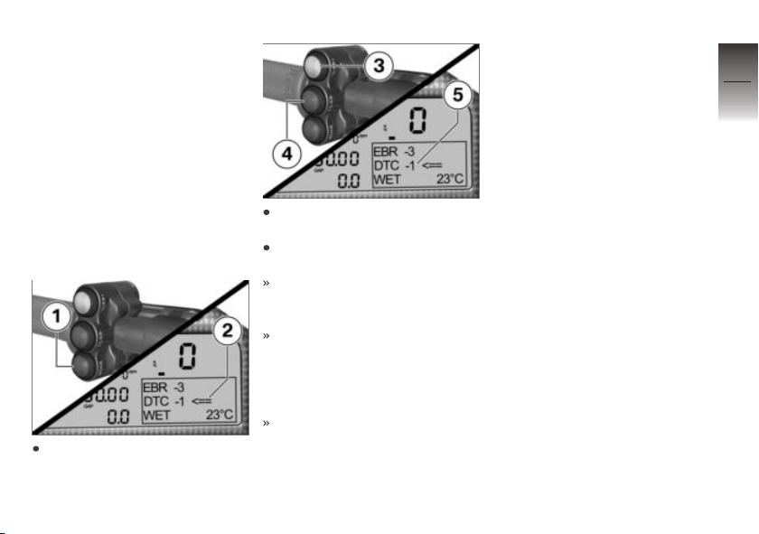
DTC
DTC setting
A setting for DTC is stored in
each module. This settings can
be adjusted to individual needs
both when parked and during
riding.
Adapt DTC
Requirement
Multifunction display must show
the rider view
Press MODE 1 to select
EBR 2.
Briefly press TC/EB+ 3 to increase the value 5.
Briefly press TC/EB- 4 to reduce the value 5.
The set value 5 is shown in the
multifunction display and lies
between 7 and +7:
+1 … +7: reduction of the slip
on the rear wheel by a maximum of seven stages. The
value +7 corresponds to the
earliest DTC intervention.
1 … 7: increase of the slip
on the rear wheel by a maximum of seven stages. The
value 7 corresponds to the
latest DTC intervention.
DTC deactivation
On very loose surfaces (e.g. a
gravel bed at a racetrack) the
control interventions of the DTC
can reduce the drive power at
the rear wheel to such a degree
that the rear wheel no longer
turns sufficiently. In this case,
BMW Motorrad recommends
switching off the DTC temporarily.
Note that the rear wheel will spin
on the loose surface, and close
the throttle in a timely manner
before reaching a solid surface.
Then switch on the DTC again.
EBR
EBR setting
A setting for EBR is stored in
each module. This settings can
be adjusted to individual needs
both when parked and during
riding.
7
93
z
In the pit
Page 96
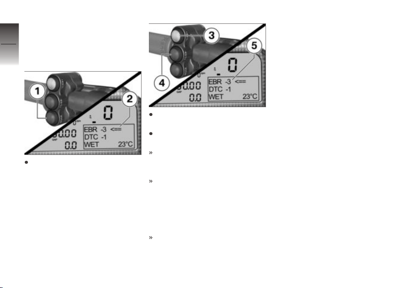
Adapt EBR
7
Requirement
Multifunction display must show
94
the rider view
z
In the pit
Press MODE 1 to select
EBR 2.
Briefly press TC/EB+ 3 (+) to
increase the value 5.
Briefly press TC/EB-4 (-) to
reduce the value 5.
The set value 5 is shown in the
multifunction display and lies
between 7 and +7:
+1 … +7: increase the drag
torque at the rear wheel by a
maximum of seven stages. The
value +7 corresponds to the
highest braking effect through
the engine drag torque.
1 … 7: reduction of the drag
torque at the rear wheel by a
maximum of seven stages. The
value 7 corresponds to the
lowest braking effect through
the engine drag torque.
Gearshift-pattern reverser
Gearshift-pattern reverser
The motorcycle is equipped by
default with a shift pattern that
offers the best and quickest way
to shift gears for the racing track.
If desired, the shift pattern can
be inverted by modifying the
gearshift rod. As for driving on
public roads, first gear can then
be engaged by pushing downward and all other gears by pushing upward.
Page 97
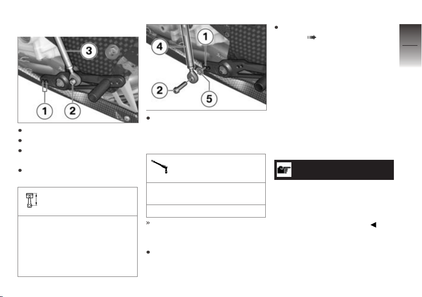
Reversing shift pattern
Clean desired thread 1.
Remove the screw 2.
Remove washer between ball
joint and gearshift lever.
Reposition gearshift rod 3 onto
desired thread 1.
Gearshift rod attachment
points on gearshift lever
Thread for outer pivot point
(Basic setting for both shift
patterns)
Thread for outer or inner pivot
point (Adjustment range for
both shift patterns)
Insert bolt 2 through ball
joint 4 and washer 5, install
in thread 1 and tighten to
specified torque.
Shift rod on gearshift
lever
Joint compound: Lubricate
thread, Optimoly TA
6 lb/ft (8 Nm)
Shifting is then setup for operation with the standard shift
pattern.
Check and, if necessary, adjust
the gearshift lever height.
Adjust the gearshift lever
height ( 68).
Data recording and 2D software
Data recording and 2D
software
You will find all the necessary information and support for dealing
with the 2D software as well as
reading out and evaluating the
recorded driving data on:
2d-datarecording.com
NOTICE
The motorcycle can only be operated if a 2D data logger is connected.
Do not remove data logger or
replace with another brand.
7
95
z
In the pit
Page 98
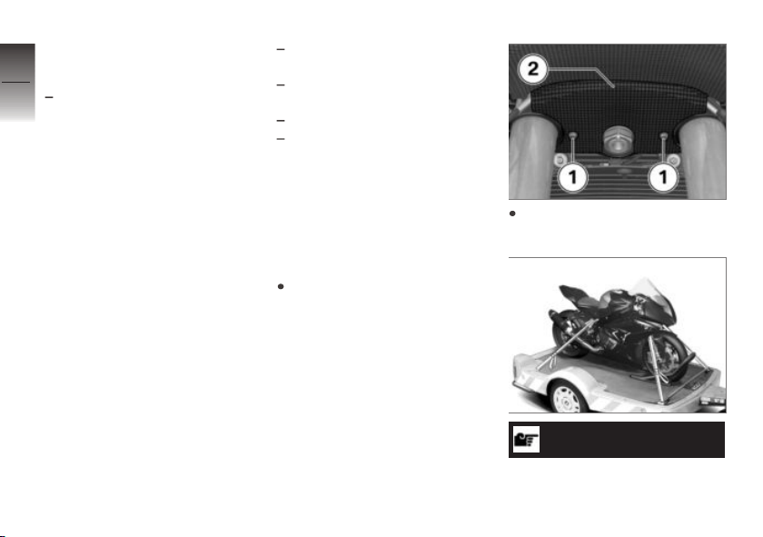
HP Race
7
Calibration Kit Pro
96
with HP Callibration Kit Pro
With the HP Race
Calibration Kit Pro it is possible
to access various parameters
of the engine control unit and
adjust the settings. To discover
more information about this, see
the HP Race Calibration Kit Pro
accompanying the operating
z
In the pit
instructions, or visit the website
on:
bmw-motorrad.com/hprace
Connector for optional accessories
Equipment
The vehicle is equipped with the
following connectors for special
and racing accessories:
Front and rear brake pressure
sensors
Front and rear spring travel
OA
sensors
Infrared receiver
CAN-Bus connection
You will find a more detailed
description in the Accessories
chapter.
Securing motorcycle for transport
Protect all component surfaces
against which straps are routed
against scratching. For example, use adhesive tape or soft
cloths.
Remove bolts 1 and fork partition 2.
ATTENTION
Motorcycle tips to the side
when raising
Page 99
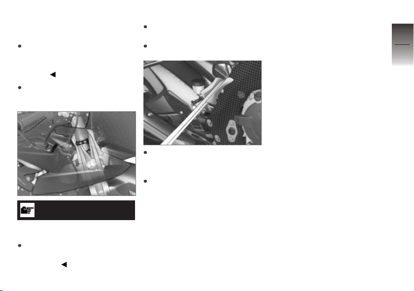
Component damage cause by
tipping over
Secure the motorcycle against
tipping to the side, preferably
with the assistance of a second
person.
Push motorcycle onto transport
surface.
ATTENTION
Pinching of components
Component damage
Do not pinch components,
e.g. brake lines or wiring
harnesses.
Lay straps at front over lower
fork bridge on both sides.
Tension straps downward.
Place straps at rear on both
sides on rear frame and tension.
Tension all straps evenly; the
motorcycle should be pulled
down against its springs with
the suspension compressed as
much as possible.
7
97
z
In the pit
Page 100

7
98
z
In the pit
 Loading...