

Page 1
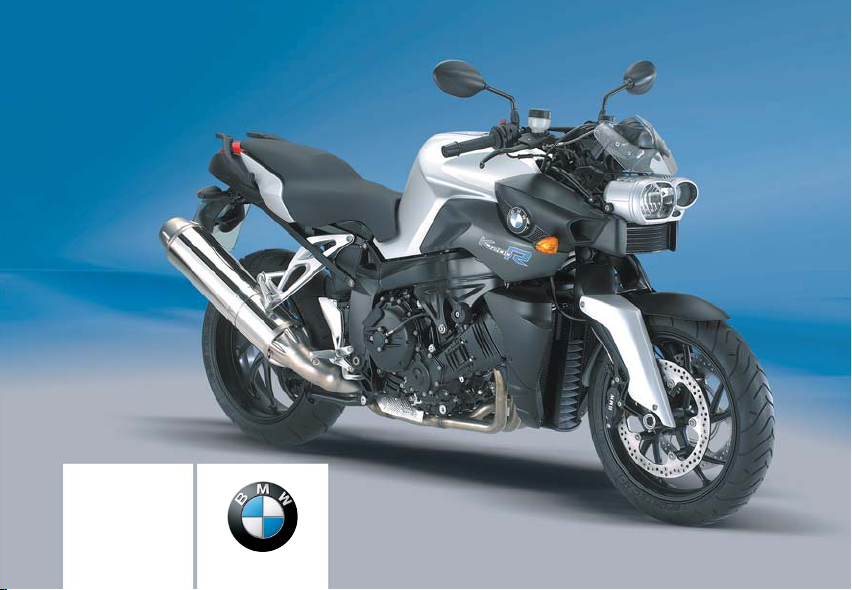
Rider's Manual (US Model)
K 1200 R
BMW Motorrad
The Ultimate Riding
Machine
Page 2

Motorcycle/Retailer Data
Motorcycle data
Model
Vehicle Identification Number
Color number
First registration
Registration number
Retailer Data
Contact in Service
Ms./Mr.
Phone number
Retailer's address/phone number (company stamp)
Page 3

Welcome to BMW
We congratulate you on your
choice of a motorcycle from
BMW and welcome you to the
community of BMW riders.
Familiarize yourself with your new
motorcycle so that you can ride it
safely and confidently in all traffic
situations.
Please read this Rider's Manual
carefully before starting to use
your new BMW motorcycle. It
contains important information on
how to operate the controls and
how to make the best possible
use of all your BMW's technical
features.
In addition, it contains information
on maintenance and care to help
you maintain your motorcycle's
reliability and safety, as well as its
value.
If you have any questions concerning your motorcycle, your authorized BMW Motorrad retailer
is always happy to provide advice
and assistance.
We wish you many miles of safe
and enjoyable riding
BMW Motorrad.
Page 4

Table of Contents
You can also use the index at the
end of this Rider's Manual to find
a specific topic.
1 General instructions . .. . . 5
Overview . . . . . . . . . . . . . . . . . . . . . . 6
Abbreviations and symbols . . . . 6
Equipment . . . . . . . . . . . . . . . . . . . . 7
Technical data . . . . . . . . . . . . . . . . 7
Currentness of this manual . . . . 7
2 Overviews . .. ... ... ... ... .. 9
General view, left side . . . . . . . . 11
General view, right side . . . . . . 13
Underneath seat . . . . . . . . . . . . . 15
Left handlebar fitting . . . . . . . . . 16
Handlebar fitting, right . . . . . . . . 17
Instrument cluster . . . . . . . . . . . . 18
Headlight . . . . . . . . . . . . . . . . . . . . . 19
3 Status indicators . ... ... 21
Standard displays . . . . . . . . . . . . 22
Displays with onboard com-
OE
puter
Displays with Tire Pressure
Control RDC
...................... 23
OE
............... 24
Standard warning indica-
tors . . . . . . . . . . . . . . . . . . . . . . . . . . . 24
Warning indicators of onboard computer
ABS warning indica-
OE
tors
........................ 31
ASC warning indica-
OE
tors
........................ 34
RDC warning indica-
OE
tors
........................ 36
Anti-theft alarm warning indi-
OE
cators
OE
........... 29
..................... 41
4 Operation .. . .. ... .. . .. ... 45
Ignition switch and steering
lock . . . . . . . . . . . . . . . . . . . . . . . . . . 46
Electronic immobilizer
EWS ......................... 47
Clock . . . . . . . . . . . . . . . . . . . . . . . . . 48
Odometer and tripmeters . . . . 49
Onboard computer
Tire Pressure Control
OE
RDC
....................... 55
OE
........ 52
Lights . . . . . . . . . . . . . . . . . . . . . . . . 56
Turn indicators . . . . . . . . . . . . . . . 57
Hazard warning flashers . . . . . . 58
Emergency ON/OFF
switch . . . . . . . . . . . . . . . . . . . . . . . . 59
Heated hand grips
Automatic Stability Control
OE
ASC
....................... 60
OE
......... 59
Clutch . . . . . . . . . . . . . . . . . . . . . . . . 61
Brakes . . . . . . . . . . . . . . . . . . . . . . . 61
Mirrors . . . . . . . . . . . . . . . . . . . . . . . 62
Spring preload . . . . . . . . . . . . . . . 63
Damping . . . . . . . . . . . . . . . . . . . . . 63
Electronic suspension adjustment ESA
OE
................. 64
Tires . . . . . . . . . . . . . . . . . . . . . . . . . 66
Headlight . . . . . . . . . . . . . . . . . . . . . 67
Seat . . . . . . . . . . . . . . . . . . . . . . . . . . 67
Helmet holder . . . . . . . . . . . . . . . . 69
Luggage loops . . . . . . . . . . . . . . . 70
5 Riding .. .. .. .. .. .. .. .. .. .. 71
Safety instructions . . . . . . . . . . . 72
Checklist . . . . . . . . . . . . . . . . . . . . . 73
Starting. . . . . . . . . . . . . . . . . . . . . . . 74
Running in . . . . . . . . . . . . . . . . . . . 77
Brakes . . . . . . . . . . . . . . . . . . . . . . . 78
Page 5

Parking your motorcycle . . . . . 79
Refueling . . . . . . . . . . . . . . . . . . . . . 80
6 Technology in detail . .. 83
Brake system with BMW Motorrad Integral ABS
Engine management with
BMW Motorrad ASC
Tire Pressure Control
OE
RDC
....................... 87
OE
........ 84
OE
...... 86
7 Accessories . .. .. .. .. .. .. 89
General instructions . . . . . . . . . . 90
Onboard socket . . . . . . . . . . . . . . 90
Luggage . . . . . . . . . . . . . . . . . . . . . 91
OA
Case
...................... 92
8 Maintenance . . .. ... .. . .. 97
General instructions . . . . . . . . . . 98
Toolkit. . . . . . . . . . . . . . . . . . . . . . . . 98
Engine oil . . . . . . . . . . . . . . . . . . . . 99
General brake system . . . . . . 101
Brake pads . . . . . . . . . . . . . . . . . 101
Brake fluid . . . . . . . . . . . . . . . . . . 103
Clutch . . . . . . . . . . . . . . . . . . . . . . 105
Tires . . . . . . . . . . . . . . . . . . . . . . . 106
Rims . . . . . . . . . . . . . . . . . . . . . . . 106
Wheels . . . . . . . . . . . . . . . . . . . . . 107
Front wheel stand . . . . . . . . . . 114
Rear-wheel stand . . . . . . . . . . 115
Lamps . . . . . . . . . . . . . . . . . . . . . . 116
Jump-starting . . . . . . . . . . . . . . 123
Battery . . . . . . . . . . . . . . . . . . . . . 124
9 Care . .. ... .. . .. ... .. .. .. . 129
Care products . . . . . . . . . . . . . . 130
Washing your motorcy-
cle.......................... 130
Cleaning sensitive motorcy-
cle parts . . . . . . . . . . . . . . . . . . . . 130
Paint care . . . . . . . . . . . . . . . . . . 131
Protective wax coating . . . . . 132
Storing motorcycle . . . . . . . . . 132
Returning motorcycle to
use ......................... 132
10 Technical data . .. . .. . 133
Troubleshooting chart . . . . . . 134
Threaded fasteners . . . . . . . . 135
Engine . . . . . . . . . . . . . . . . . . . . . 137
Fuel . . . . . . . . . . . . . . . . . . . . . . . . 138
Engine oil . . . . . . . . . . . . . . . . . . 138
Clutch . . . . . . . . . . . . . . . . . . . . . . 139
Transmission . . . . . . . . . . . . . . . 139
Rear-wheel drive . . . . . . . . . . . 140
Running gear . . . . . . . . . . . . . . . 140
Brakes . . . . . . . . . . . . . . . . . . . . . 141
Wheels and tires . . . . . . . . . . . 141
Electrical system . . . . . . . . . . . 144
Frame . . . . . . . . . . . . . . . . . . . . . . 146
Dimensions . . . . . . . . . . . . . . . . 146
Weights . . . . . . . . . . . . . . . . . . . . 147
Riding specifications . . . . . . . 147
11 Service . .. .. .. .. . . .. .. . 149
BMW Motorrad Service . . . . 150
BMW Motorrad Service
Quality . . . . . . . . . . . . . . . . . . . . . 150
BMW Motorrad Service
Card - On-the-spot break-
down assistance . . . . . . . . . . . 150
BMW Motorrad Service
Network . . . . . . . . . . . . . . . . . . . . 151
Maintenance work . . . . . . . . . . 151
Confirmation of mainte-
nance work . . . . . . . . . . . . . . . . . 152
Confirmation of service . . . . . 157
Reporting
.
Safety Defects.........
163
Page 6

Page 7

General instructions
Overview ............................. 6
Abbreviations and symbols ........... 6
Equipment ............................ 7
Technical data ........................ 7
Currentness of this manual ........... 7
1
z
5
General instructions
Page 8
Overview
1
Chapter 2 of this Rider's Manual will provide you with an initial
6
overview of your motorcycle. All
maintenance and repair work carried out on your motorcycle will
be documented in Chapter 11.
Proof of the maintenance work
performed is a prerequisite for
generous treatment of claims.
When the time comes to sell
your BMW, please remember
to hand over this Rider's Manual; it is an important part of the
motorcycle.
Abbreviations and
z
General instructions
symbols
Indicates warnings that you
must comply with for reasons of your safety and the safety of others, and to protect your
motorcycle against damage.
Special information on op-
erating and inspecting your
motorcycle as well as maintenance and adjustment procedures.
Indicates the end of an
item of information.
Instruction.
Result of an activity.
Reference to a page with
more detailed information.
Indicates the end of accessory or equipmentdependent information.
Tightening torque.
Technical data.
OE Optional equipment
The motorcycles are assembled complete with
all the BMW optional extras originally ordered.
OA Optional accessories
BMW optional accessories can be purchased
and installed at your authorized BMW Motorrad
retailer.
Electronic immobilizer.
EWS
DWA
Anti-theft alarm.
ABS Anti-Lock Brake System.
ASC Automatic Stability Con-
trol.
ESA Electronic Suspension
Adjustment
Electronic suspension
adjustment.
Page 9

TPC Tire Pressure Control.
Equipment
When you ordered your BMW
Motorrad, you chose various
items of custom equipment. This
Rider's Manual describes optional extras (OE) offered by BMW
and selected optional accessories
(OA). This explains why the manual may also contain descriptions
of equipment which you have not
ordered. Please note, too, that
your motorcycle might not be exactly as illustrated in this manual
on account of country-specific
differences.
If your BMW is equipped with
options or accessories not described in this Rider's Manual,
then this equipment is described
in a separate operating manual.
Technical data
All dimensions, weights and outputs in the Rider's Manual refer
to the Deutsche Institut für Normung e. V. (DIN) and comply with
its tolerance regulations. Versions for individual countries may
differ.
Currentness of this manual
The high safety and quality standards of BMW motorcycles are
maintained by constant development work on designs, equipment and accessories. Because
of this, your motorcycle may differ from the information supplied
in the Rider's Manual. In addition,
BMW Motorrad cannot guarantee
the total absence of errors. We
hope you will appreciate that no
claims can be entertained on the
basis of the data, illustrations or
descriptions in this manual.
1
z
7
General instructions
Page 10

1
z
8
General instructions
Page 11

Overviews
General view, left side................ 11
General view, right side . . ............ 13
Underneath seat ..................... 15
Left handlebar fitting ................. 16
Handlebar fitting, right . . . ............ 17
Instrument cluster ................... 18
Headlight ............................ 19
2
9
z
Overviews
Page 12
2
10
z
Overviews
Page 13

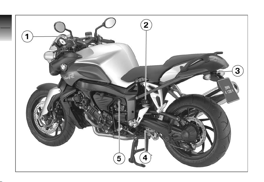
General view, left side
1 Clutch fluid reservoir
( 105)
2 Adjuster for spring preload,
rear ( 63)
3 Seat lock (below tail light)
( 67)
4 Adjustment of rear damping
( 64)
5 Onboard socket ( 90)
2
11
z
Overviews
Page 14
2
12
z
Overviews
Page 15

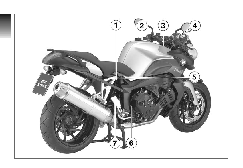
General view, right side
1 Engine oil level indicator
( 99)
2 Fuel filler opening ( 80)
3 Battery compartment
( 126)
4 Brake-fluid reservoir, front
( 101)
5 Type plate (on rear cross
tube)
6 Vehicle identification num-
ber (on front right side panel)
7 Brake-fluid reservoir, rear
( 104)
2
13
z
Overviews
Page 16

2
14
z
Overviews
Page 17

Underneath seat
1 Engine oil fill location
( 100)
2 Toolkit ( 98)
3 Helmet holder ( 69)
2
15
z
Overviews
Page 18

Left handlebar fitting
2
1 Operating odometer
16
z
( 49), Operating onboard
computer
2 Operating the ASC
( 60)
3 Operating ESA
4 Horn
5 Turn indicators, left ( 57),
Hazard warning flashers
( 58)
6 High-beam headlight and
Overviews
headlight flasher ( 56)
OE
( 52)
OE
OE
( 64)
Page 19
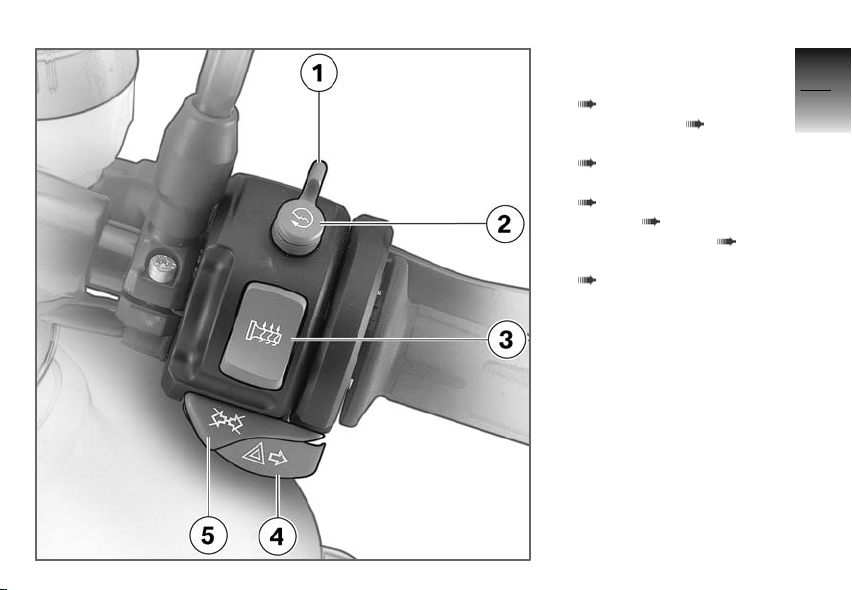
Handlebar fitting, right
1 Emergency ON/OFF switch
( 59)
2 Starter button ( 74)
3 Heated hand grips
( 59)
4 Turn indicators, right
( 57), Hazard warning
flashers ( 58)
5 Turn indicators off ( 57),
Hazard warning flashers off
( 58)
OE
2
17
z
Overviews
Page 20
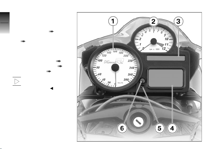
Instrument cluster
2
1 Speedometer
2 Tachometer
18
3 Indicator lights ( 22)
4 Multifunction display
( 22)
5 Anti-theft alarm indicator
light (OE) and instrument
lighting sensor
6 Selecting readings ( 49)
Resetting tripmeter ( 50)
z
Setting clock ( 48)
Overviews
The instrument-cluster
lighting has automatic day
and night switchover.
Page 21

Headlight
1 High-beam headlight
2 Low-beam headlight
3 Parking lights
2
19
z
Overviews
Page 22

2
20
z
Overviews
Page 23

Status indicators
Standard displays .................... 22
Displays with onboard comput-
erOE................................. 23
Displays with Tire Pressure Control
OE
RDC
Standard warning indicators ......... 24
Warning indicators of onboard com-
puterOE.............................. 29
ABS warning indicators
ASC warning indicatorsOE........... 34
RDC warning indicatorsOE........... 36
Anti-theft alarm warning indica-
torsOE............................... 41
.............................. 24
OE
........... 31
3
21
z
Status indicators
Page 24
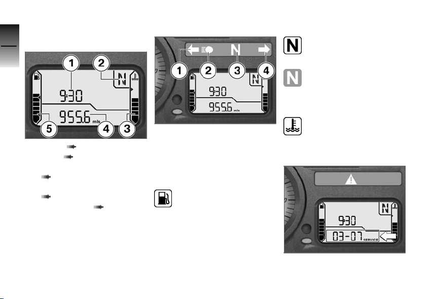
Standard displays
3
Multifunction display
22
1 Clock ( 48)
2 Gear ( 22)
3 Coolant temperature
z
( 22)
Status indicators
4 Odometer and tripmeters
( 49)
5 Fuel capacity ( 22)
Indicator lights
1 Turn indicators, left
2 High-beam headlight
3 Idling
4 Turn indicators, right
Fuel capacity
The horizontal bars under
the gas pump symbol indicate the remaining fuel quantity.
When the fuel in the tank is
topped up the gauge briefly
shows the original level, before
the reading is updated.
Gear
The gear engaged or N
for neutral appears on the
display.
If no gear is engaged, the
'neutral' indicator light also
lights up.
Coolant temperature
The lateral bars under the
temperature symbol show
the coolant temperature level.
Service display
If the time remaining until the
next service lies within a month,
Page 25
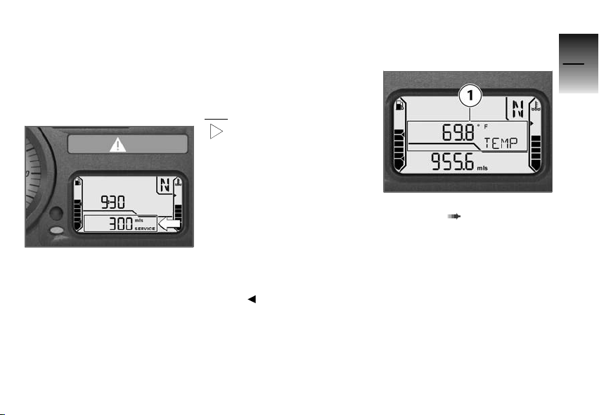
the service date is briefly displayed following the pre-ride
check. The month and year are
shown as two digits each separated by a dash; in this example
the display means "March 2007".
If the motorcycle is driven long
distances annually, it is possible
that earlier service is required. If
the odometer reading for the earlier service lies within 600 miles
(1,000 km), the remaining miles
(kilometers) are counted down
in 60-mile (100-km) steps and
briefly displayed following the
pre-ride check.
If the service interval has been
exceeded, the general warning
light also lights up yellow in addition to the date or mileage display. The Service lettering is displayed continuously.
If the service display already
more than one month before the service date, or if the
Service lettering does not stop
after the service date is exceeded, then the date stored in the
instrument cluster must be set.
This situation can occur if the
battery has been disconnected
for a longer time.
Consult a certified workshop,
preferably an authorized BMW
Motorrad retailer, for setting of
the date.
Displays with onboard
OE
OE
( 52)
computer
1 Onboard computer display
area
3
23
z
Status indicators
Page 26
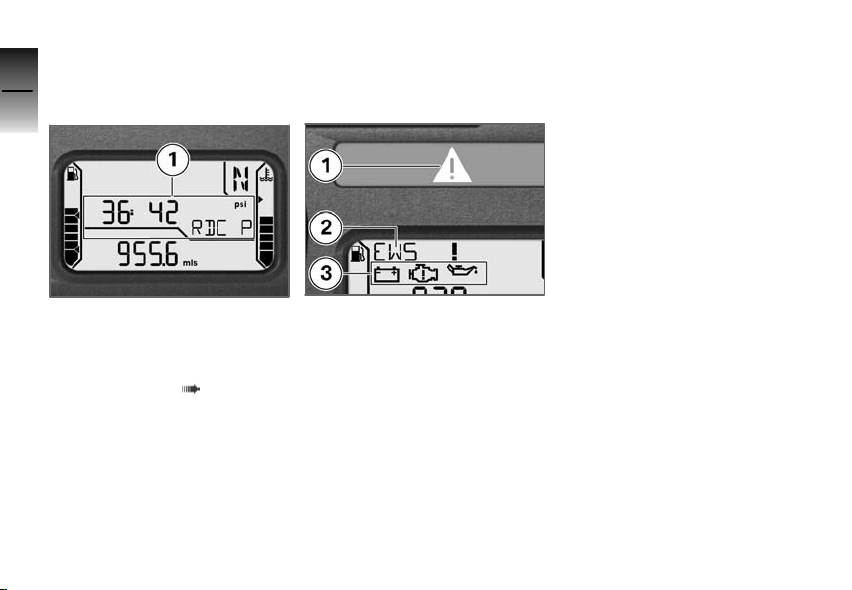
Displays with Tire
3
Pressure Control
OE
RDC
24
Standard warning indicators
Display
The possible warnings are listed
on the next page.
1 Tire inflation pressures al-
ternating with clock, with
z
onboard computer as ad-
Status indicators
ditional value of onboard
computer.
OE
( 55)
Warnings are indicated by the
'General' warning light 1 showing in combination with a warning
word, for example 2 or with one
of the warning symbols 3. The
'General' warning light shows red
or yellow, depending on the urgency of the warning. If several warnings are active, all corresponding warning lights and
warning symbol are displayed;
warnings are shown alternately.
Page 27
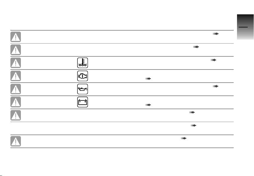
Overview of warning indicators
Meaning
Lights up yellow EWS ! appears on
Lights up yellow
Lights up red Temperature dis-
Lights up yellow Is indicated Engine in emergency-operation mode
Flashes red Is indicated
the display.
FUEL ! appears
on the display.
play flashes
Electronic immobilizer is active ( 26)
Fuel down to reserve ( 26)
Coolant temperature too high ( 26)
( 26)
Engine oil pressure insufficient ( 27)
3
25
Lights up red Is indicated
Lights up yellow
LAMPR ! appears
on the display.
LAMPF ! appears
on the display.
Lights up yellow
LAMPS ! appears
on the display.
Battery charge current insufficient
( 27)
Rear bulb defective ( 28)
Front bulb defective ( 28)
Bulbs defective ( 28)
z
Status indicators
Page 28
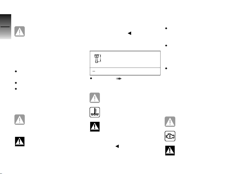
Electronic immobilizer is
active
3
26
General warning light shows
yellow.
EWS ! appears on the display.
The key being used is not authorized for starting, or communication between the key and engine
electronics is disrupted.
Remove other ignition keys
located on the ignition key.
Use the reserve key.
Have the defective key replaced, preferably by an authorized BMW Motorrad retailer.
z
Status indicators
Fuel down to reserve
General warning light shows
yellow.
FUEL ! appears on the display.
A fuel shortage can lead to
misfiring and to the engine
dying unexpectedly. Misfiring can
damage the catalytic converter,
and the engine dying unexpected
can lead to accidents.
Do not drive until the fuel tank is
completely empty.
At the most, the fuel tank still
contains the reserve fuel quantity.
Reserve fuel quantity
≥1.1 gal (≥4l)
Refueling ( 80)
Coolant temperature too high
General warning light shows
red.
Temperature display flashes.
Continued driving with an
overheated engine can result in engine damage.
Be sure to observe the measures
listed below.
The coolant temperature is too
high.
If possible, continue driving
in the part-load range to cool
down the engine.
In traffic jams, switch off the
engine, but keep the ignition
switched on so that the radiator fan continues to operate.
Should the coolant temperature
frequently be too high, have
the fault rectified as quickly as
possible by a specialized workshop, preferably an authorized
BMW Motorrad retailer.
Engine in emergencyoperation mode
General warning light shows
yellow.
Engine symbol appears on
the display.
The engine is in the emergency operating mode. On-
ly reduced engine performance
Page 29
may be available, which can lead
to danger driving situations, especially during passing maneuvers.
Adapt your driving style to
the possibly reduced engine
performance.
The engine control unit has diagnosed a fault. In exceptional
cases, the engine stops and can
no longer be started. Otherwise,
the engine runs in the emergency operating mode.
Continued driving is possible,
however the accustomed engine performance may not be
available.
Have the malfunction corrected
as soon as possible by a specialized workshop, preferably
an authorized BMW Motorrad
retailer.
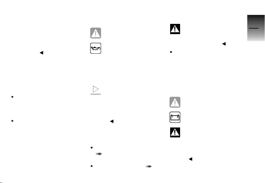
Engine oil pressure
insufficient
General warning light flashes red.
Oil-can symbol appears on
the display.
The oil pressure in the lubricating
oil circuit is too low. If the warning light lights up, stop immediately and switch off the engine.
The warning on insuffi-
cient engine oil pressure
is no substitute for the function of an oil-level indicator. The
correct engine oil level can only be checked on the oil level
indicator.
The cause of the warning on insufficient engine oil pressure can
be an insufficient engine oil level.
Checking engine oil level
( 99)
If oil level is too low:
Topping up engine oil ( 100)
If the engine oil level is correct:
Driving with insufficient en-
gine oil pressure can result
in engine damage.
Do not continue driving.
Have the malfunction corrected
as soon as possible by a specialized workshop, preferably
an authorized BMW Motorrad
retailer.
Battery charge current
insufficient
General warning light shows
red.
Battery symbol appears on
the display.
A discharged battery can
result in the engine cutting
out unexpectedly, causing a hazardous situation.
Have faults eliminated as soon as
possible.
3
27
z
Status indicators
Page 30
If the battery is no longer
3
28
z
Status indicators
charged, continued driving
can lead to deep discharging,
and therefore to the destruction
of the battery.
If possible, do not continue
driving.
The battery is not being charged.
Continued driving is possible
until the battery is discharged.
However, the engine can die
suddenly and the battery can
be exhaustively discharged and
therefore destroyed.
Have the malfunction corrected
as soon as possible by a specialized workshop, preferably
an authorized BMW Motorrad
retailer.
Rear bulb defective
General warning light shows
yellow.
LAMPR ! appears on the dis-
play.
A defective bulb places
your safety at risk because
it is easier for other users to
oversee the motorcycle.
Replace defective bulbs as
soon as possible; always carry a
complete set of spare bulbs if
possible.
Rear light or brake light bulb defective.
Replacing brake and tail light
bulb ( 120)
Front bulb defective
LAMPF ! appears on the dis-
play.
A defective bulb places
your safety at risk because
it is easier for other users to
oversee the motorcycle.
Replace defective bulbs as
soon as possible; always carry a
complete set of spare bulbs if
possible.
Low-beam headlight, high-beam
headlight, parking light or turn
signal bulb defective.
Replacing low-beam and highbeam bulb ( 117)
Replacing parking light bulb
( 119)
Replacing front and rear turn
indicator bulbs ( 122)
Bulbs defective
General warning light shows
yellow.
LAMPS ! appears on the dis-
play.
A defective bulb places
your safety at risk because
it is easier for other users to
oversee the motorcycle.
Replace defective bulbs as
soon as possible; always carry a
complete set of spare bulbs if
possible.
Page 31
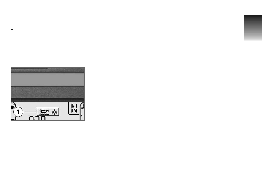
A combination of several bulb
defects is present.
See the fault descriptions
above.
3
29
Warning indicators of
onboard computer
Display
Warnings of the onboard computer are shown in area 1.
The possible warnings are listed
on the next page.
OE
z
Status indicators
Page 32
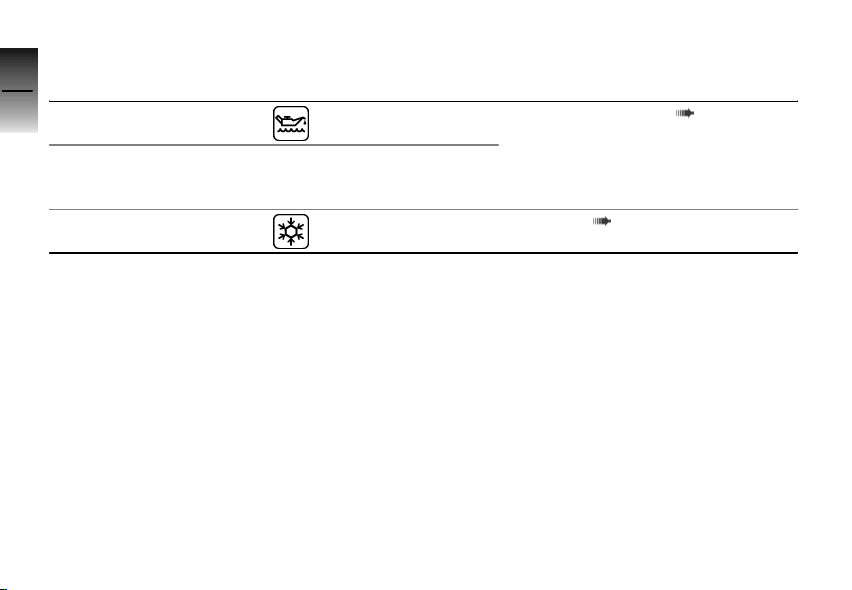
Overview of warning indicators
3
30
z
Status indicators
Meaning
Is indicated Engine oil level too low ( 31)
Check Oil ap-
pears on the display
Is indicated Ice warning ( 31)
Page 33
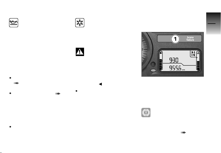
Engine oil level too low
Oil level symbol appears on
the display.
Check Oil appears on the
display.
The electronic oil level sensor
has detected a low engine oil
level.
The exact engine oil level can
only be determined by conducting a check of oil level indicator.
During the next refueling stop:
Checking engine oil level
( 99)
If oil level is too low:
Topping up engine oil ( 100)
If "Check oil level" appears in
the display, although a correct
oil level has been measured on
the oil level indicator, the oil level
sensor may be defective.
Contact a specialized workshop, preferably an authorized
BMW Motorrad retailer.
Ice warning
Ice crystal symbol appears
on the display.
The air temperature measured
at the motorcycle is lower than
37 °F (3 °C).
The ice warning does not
mean that there is no risk
of black ice forming at measured
temperatures above 37 °F (3 °C).
Always think well ahead when
temperatures are low, especially
on bridges and where the road is
in the shade.
Think well ahead when driving.
ABS warning
indicators
Display
ABS warnings are indicated by
the ABS warning light 1.
In some countries an alternative
display of the ABS warning light
is possible.
Possible country-dependent
versions.
Additional information on the
BMW Motorrad Integral ABS is
provided from page ( 84); an
OE
3
31
z
Status indicators
Page 34

overview of the possible warnings
is provided on the following page.
3
32
z
Status indicators
Page 35
Overview of warning indicators
Flashes
Lights up
Meaning
ABS self-diagnosis not completed
( 34)
ABS error ( 34)
3
33
z
Status indicators
Page 36
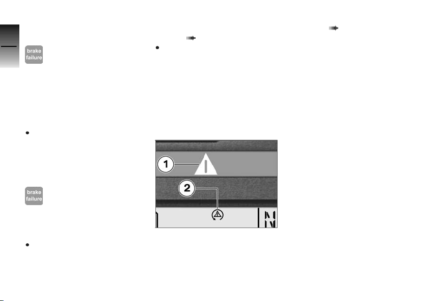
ABS self-diagnosis not
completed
3
34
z
Status indicators
ABS warning light flashes.
The ABS function is not available, because the self-diagnosis has not been completed. To
check the wheel sensors, the
motorcycle must be driven a few
yards.
Ride off slowly. It must be noted that the ABS function is not
available until the self-diagnosis
has been completed.
ABS error
ABS warning light lights up.
The ABS control unit has detected an error. The ABS function is
not available.
Continued driving is possible
while taking the failed ABS
function into account. Observe
additional information on situa-
tions which can lead to an ABS
error ( 85).
Have the malfunction corrected
as soon as possible by a specialized workshop, preferably
an authorized BMW Motorrad
retailer.
ASC warning
indicators
Display
ASC warnings are displayed with
the ASC symbol 2 in conjunction
with the general warning light 1.
Additional information on the
BMW Motorrad ASC is provided
OE
from page ( 86); an overview
of the possible warnings is provided on the following page.
Page 37
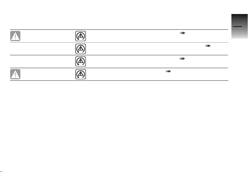
Overview of warning indicators
Flashes rapidly in
yellow
Is indicated
Flashes
Meaning
ASC intervention ( 36)
Self-diagnosis not completed ( 36)
3
35
Is indicated
Lights up yellow Is indicated
ASC deactivated ( 36)
ASC error ( 36)
z
Status indicators
Page 38
ASC intervention
3
36
z
Status indicators
General warning light flashes rapidly in yellow.
ASC symbol is displayed.
The ASC has detected instability at the rear wheel and has
reduced the torque. The warning light flashes longer than the
duration of the ASC intervention.
As a result, the driver is provided
with optical feedback on the regulation carried out even after the
critical driving situation.
Self-diagnosis not completed
ASC symbol flashes.
The self-diagnosis was not completed; the ASC function is not
available. So that the ASC selfdiagnosis can be completed, the
engine must be running and the
motorcycle must be moved at a
speed of at least 3 mph (5 km/h).
Ride off slowly. It must be noted that the ASC function is not
available until the self-diagnosis
has been completed.
ASC deactivated
ASC symbol is displayed.
The ASC system has been deactivated by the driver.
With OE Automatic Stability
Control (ASC):
Activating ASC function ( 60)
ASC error
General warning light shows
yellow.
ASC symbol is displayed.
The ASC control unit has detected an error. The ASC function is
not available.
Continue driving is possible. It
must be noted that the ASC
function is not available. Ob-
serve additional information on
situations which can lead to an
ASC error ( 87).
Have the malfunction corrected
as soon as possible by a specialized workshop, preferably
an authorized BMW Motorrad
retailer.
RDC warning
indicators
Display
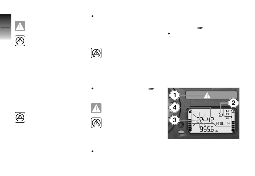
The warning symbol 2 signals
a critical tire inflation pressure,
and the corresponding inflation
OE
Page 39

pressure of the front wheel 3 or
the rear wheel 4 flashes.
If the critical value is at the limit
of the permissible tolerance, the
general warning light 1 also lights
up in yellow. If the determined
tire inflation pressure is outside
the permissible tolerance, the
general warning light flashes in
red.
Additional information on the
BMW Motorrad RDC is provided
from page ( 87); an overview
of the possible warnings is provided on the following page.
3
37
z
Status indicators
Page 40
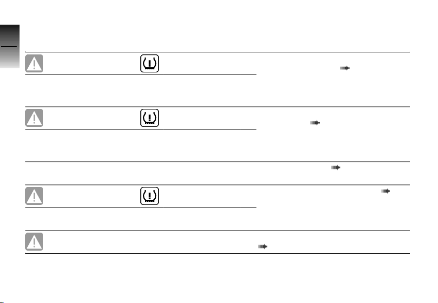
Overview of warning indicators
3
38
z
Status indicators
Lights up yellow
Flashes red
Lights up yellow
Lights up yellow
The critical tire
inflation pressure
flashes
The critical tire
inflation pressure
flashes
"
--"or"-- --"
is displayed
"
--"or"-- --"
is displayed
RDC! appears on
the display
Meaning
Tire inflation pressure in limit area of
permissible tolerance ( 39)
Tire inflation pressure outside permissible tolerance ( 39)
Transmission error ( 39)
Sensor defective or system fault ( 40)
Battery of tire pressure sensor weak
( 40)
Page 41
Tire inflation pressure in limit
area of permissible tolerance
General warning light shows
yellow.
Tire symbol appears on the
display.
The critical tire inflation pressure
flashes.
The measured tire inflation pressure is in the limit area of the
permissible tolerance.
Correct tire inflation pressure in
accordance with instructions on
back of cover of Rider's Manual.
The pressure values on the
back of the cover refer to
a tire air temperature of 68 °F
(20 °C). To also adapt the tire
inflation pressure at other tire
temperatures, proceed as follows:
Calculate the difference between
the nominal value according to
the Rider's Manual and the value
determine by the RDC system.
Change the inflation pressure in
the tire by this difference using
an air pressure tester at a filling
station.
Tire inflation pressure
outside permissible tolerance
General warning light flashes red.
Tire symbol appears on the
display.
The critical tire inflation pressure
flashes.
The measured tire inflation pressure is outside the permissible
tolerance.
Check tire for damage and
drivability.
Is it still possible to drive with tire:
Incorrect tire inflation pres-
sure result in poorer handling of the motorcycle.
Always adapt your driving style
to the incorrect tire inflation
pressure.
Correct tire inflation pressure at
next opportunity.
Have the tire checked for damage by a specialized workshop,
preferably an authorized BMW
Motorrad retailer.
If you are unsure about the drivability of the tire:
Do not continue driving.
Inform roadside service.
Have the tire checked for dam-
age by a specialized workshop,
preferably an authorized BMW
Motorrad retailer.
Transmission error
--"or"-- --" is displayed.
"
The motorcycle's speed has not
exceeded the threshold of approx. 20 mph (30 km/h). The
RDC sensors do not transmit
their signal until a speed above
this threshold is reached ( 87).
Watch RDC display at higher
speed. A permanent fault has
not occurred until the general
3
39
z
Status indicators
Page 42

warning light also lights up. In
this case:
3
Have fault eliminated by a spe-
40
cialized workshop, preferably
an authorized BMW Motorrad
retailer.
There is a fault in the radio connection to the RDC sensors.
Possible causes are radio systems in the surrounding area,
which interfere with the connection between the RDC control
unit and the sensors.
Watch the RDC display in another environment. A perma-
z
Status indicators
nent fault has not occurred until the general warning light also
lights up. In this case:
Have fault eliminated by a specialized workshop, preferably
an authorized BMW Motorrad
retailer.
Sensor defective or system
fault
General warning light shows
yellow.
Tire symbol appears on the
display.
"
--"or"-- --" is displayed.
Wheels without installed RDC
sensors are mounted.
Retrofit wheel set with RDC
sensors.
One or two RDC sensors have
failed.
Have fault eliminated by a specialized workshop, preferably
an authorized BMW Motorrad
retailer.
A system fault has occurred.
Have fault eliminated by a specialized workshop, preferably
an authorized BMW Motorrad
retailer.
Battery of tire pressure
sensor weak
General warning light shows
yellow.
RDC! appears on the display.
This error message is only
displayed for a short time
following the pre-ride check.
The battery of the tire pressure
sensor no longer has its full ca-
pacity. The operation of the tire
pressure control is only ensured
for a limited time.
Contact a specialized workshop, preferably an authorized
BMW Motorrad retailer.
Page 43
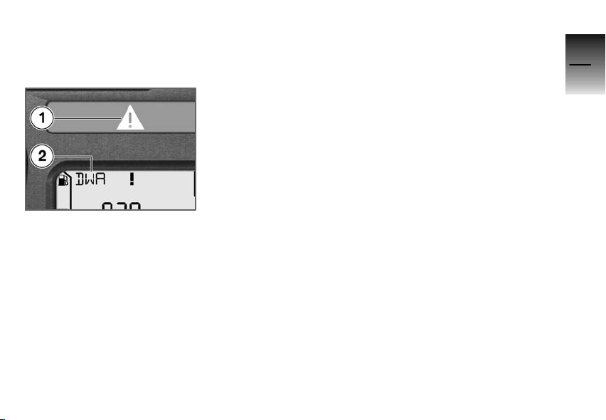
Anti-theft alarm
warning indicators
Display
Anti-theft alarm warning
are shown as warnings 2 in
conjunction with the general
warning light 1 following the
pre-ride check and refer to the
capacity of the internal anti-theft
alarm battery.
The possible warnings are listed
on the next page.
OE
3
41
z
Status indicators
Page 44
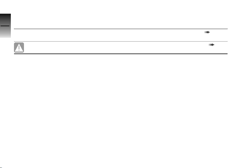
Overview of warning indicators
3
42
Lights up yellow
z
Status indicators
DWALO ! appears
on the display
DWA ! appears on
the display
Meaning
Anti-theft alarm battery weak ( 43)
Anti-theft alarm battery drained ( 43)
Page 45

Anti-theft alarm battery weak
DWALO ! appears on the dis-
play.
This error message is only
displayed for a short time
following the pre-ride check.
The anti-theft alarm battery no
longer has its full capacity. The
operation of the anti-theft alarm
is only ensured for a limited time
with the motorcycle battery disconnected.
Contact a specialized workshop, preferably an authorized
BMW Motorrad retailer.
Anti-theft alarm battery
drained
General warning light shows
yellow.
DWA ! appears on the display.
This error message is only
displayed for a short time
following the pre-ride check.
The anti-theft alarm battery has
no capacity. The operation of the
anti-theft alarm is no longer ensured with the motorcycle battery
disconnected.
Contact a specialized workshop, preferably an authorized
BMW Motorrad retailer.
3
43
z
Status indicators
Page 46

3
44
z
Status indicators
Page 47

Operation
Ignition switch and steering lock ..... 46
Electronic immobilizer EWS .......... 47
Clock ................................ 48
Odometer and tripmeters ............ 49
Onboard computerOE................ 52
Tire Pressure Control RDC
Lights ................................ 56
Turn indicators ....................... 57
Hazard warning flashers . . ............ 58
Emergency ON/OFF switch.......... 59
Heated hand gripsOE................ 59
Automatic Stability Control
ASCOE.............................. 60
Clutch ............................... 61
Brakes ............................... 61
OE
....... 55
Mirrors . . ............................. 62
Spring preload ....................... 63
Damping ............................. 63
Electronic suspension adjustment
OE
............................... 64
ESA
Tires ................................. 66
Headlight ............................ 67
Seat ................................. 67
Helmet holder ....................... 69
Luggage loops ....................... 70
4
45
z
Operation
Page 48
Ignition switch and
4
steering lock
46
Keys
You receive one master key and
one spare key. If a key is lost,
please note the information on
the electronic immobilizer (EWS)
( 47).
Ignition key and steering lock,
tank filler cap lock and seat lock
are all operated with the same
z
Operation
key.
With OA Case:
Cases with locks for the same
key can be ordered on request.
Please contact a specialized
workshop for this purpose,
preferably an authorized BMW
Motorrad retailer.
Switching on ignition
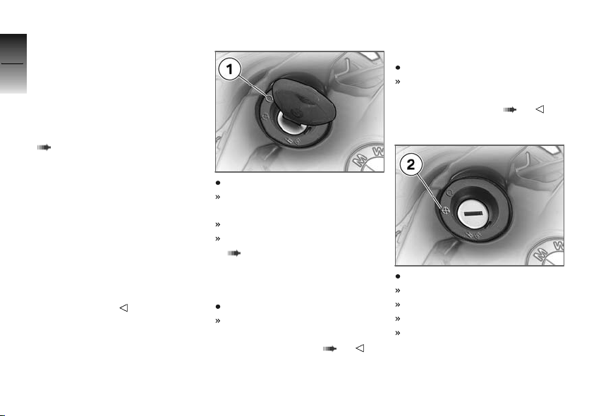
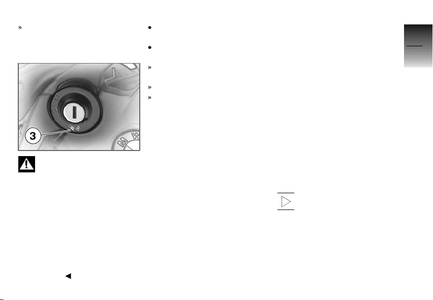
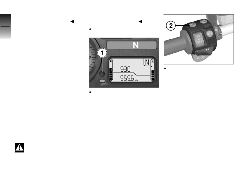
Turn key to position 1.
Parking lights and all function
circuits switched on.
Engine can be started.
Pre-ride check is performed.
( 75)
With OE BMW Motorrad Integral
ABS:
Turn key to position 1.
In addition to the points named
above, the ABS self-diagnosis
is also carried out. ( 76)
With OE Automatic Stability
Control (ASC):
Turn key to position 1.
In addition to the points named
above, the ASC self-diagnosis
is also carried out. ( 76)
Switching off ignition
Turn key to position 2.
Light switched off.
Handlebars not locked.
Key can be removed.
Electrically powered accessories remain operational for
a limited period of time.
Page 49
Battery can be recharged via
onboard socket.
Locking handlebars
If the motorcycle is on the
side stand, the surface
of the ground will determine
whether it is better to turn the
handlebars to the left or right.
However, the motorcycle is more
stable on a level surface with the
handlebars turned to the left than
with the handlebars turned to the
right.
On level ground, always turn the
handlebars to the left to set the
steering lock.
Turn handlebars to full left or
right lock position.
Turn key to position 3 while
moving handlebars slightly.
Ignition, lights and all function
circuits switched off.
Handlebars locked.
Key can be removed.
Electronic immobilizer EWS
Theft protection
The electronic immobilizer helps
protect your BMW motorcycle
from theft, and this enhanced
security is at your disposal without any need for you to set parameters or activate additional
systems. The engine of a motorcycle fitted with this electronic
immobilizer can be started only
with the keys that belong to the
motorcycle. You can also have
your authorized BMW Motorrad
retailer disable particular keys,
for example in the event that you
lose your keys. The engine cannot be started with a key that has
been barred.
Electronics in key
The motorcycle's electronics
exchange certain continuously
changing signals with the electronics in the key; these signals
are specific to your motorcycle
and they are transmitted via the
ring antenna in the ignition lock.
The ignition is not enabled for
starting until the key has been
recognized as "authorized" for
your motorcycle.
A spare key attached to
the same ring as the ignition key used to start the engine
could "irritate" the electronics,
in which case the enabling signal for starting is not issued. The
warning
multifunction display.
EWS is shown in the
4
47
z
Operation
Page 50
Always store the spare key separately from the ignition key.
4
48
Replacement and extra
keys
Replacement and spare keys
are only available through an authorized BMW Motorrad retailer.
The keys are part of an integrated security system, so the retailer is under an obligation to check
the legitimacy of all applications
z
Operation
for replacement/extra keys. If you
want to have a lost key barred,
you must bring along all other
keys that belong to the motorcycle. A key that has been barred
can subsequently be cleared and
reactivated for use.
Clock
Setting clock
Attempting to set the clock
while riding the motorcycle
can lead to accidents.
Adjust the clock only when the
motorcycle is stationary.
Switch on ignition.
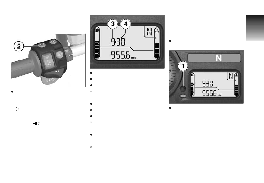
Press alternative button 2 repeatedly until total mileage is
shown.
Press button 1 repeatedly until
total mileage is shown.
Page 51
With OE Onboard computer Or
With OE Tire Pressure Control
(RDC):
Press button 2 repeatedly until
clock is shown.
In this case, the button
in the instrument cluster is only used to operate the
odometer.
Hold down button.
Hours 3 flash.
Press button.
Hours increase by one each
time button is pressed.
Hold down button.
Minutes 4 flash.
Press button.
Minutes increase by one each
time button is pressed.
Press and hold button or no
longer press it.
End setting; set time is displayed.
Odometer and tripmeters
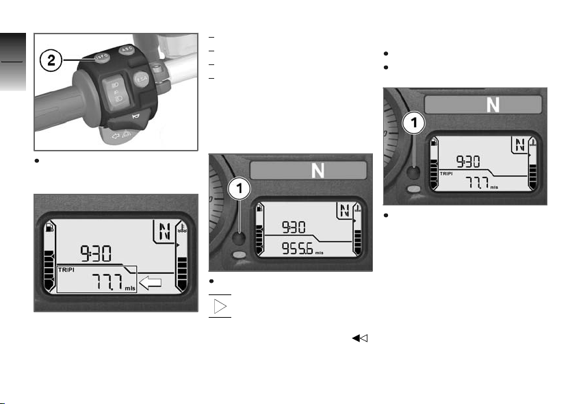
Selecting readings
Switch on ignition.
Press button 1.
4
49
z
Operation
Page 52
4
50
If you prefer, you can use button 2 for this purpose.
z
Operation
Each time the button is pressed,
the display shows values starting with the current value in the
following order:
Total distance covered
Tripmeter 1 (
Tripmeter 2 (
Operating range (after reaching
reserve level)
With OE Onboard computer Or
With OE Tire Pressure Control
(RDC):
Press button 1.
In this case, the button on
the handlebar fitting is only used to operate the onboard
computer or the RDC display.
Trip I)
Trip II)
Resetting tripmeter
Switch on ignition.
Select desired tripmeter.
Hold down button 1.
Page 53
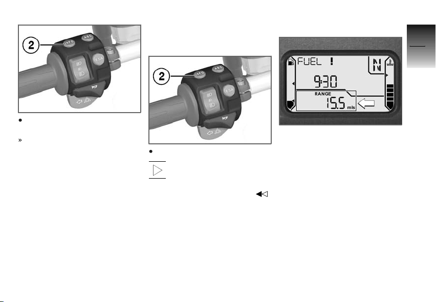
If you prefer, you can use button 2 for this purpose.
Tripmeter is reset.
With OE Onboard computer Or
With OE Tire Pressure Control
(RDC):
Hold down button 2.
In this case, the button on
the handlebar fitting is only used to operate the onboard
computer or the RDC display.
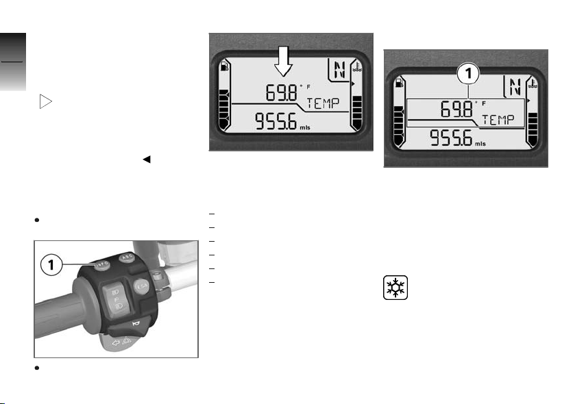
Residual range
The operating range is displayed
together with the lettering
RANGE and indicates what
distance can still be driven with
the remaining fuel. It is only
displayed after the fuel reserve
is reached. This distance is
calculated on the basis of fuel
level and average consumption.
When refueling, fuel is not registered until the quantity added is
approx. one gallon (several liters).
When refueling after running on
reserve, make sure that you top
up the tank to a level above reserve, as otherwise the sensor
4
51
z
Operation
Page 54
will not be able to register the
new level. Otherwise neither the
4
fill level nor the operating range
52
display can be updated.
The determined residual
range is an approximate
reading. BMW Motorrad therefore recommends that you do
not try to use the full remaining
range before refueling.
Onboard computer
z
Operation
Selecting readings
Switch on ignition.
Press button 1.
OE
Each time the button is pressed,
the display shows values starting with the current value in the
following order:
Ambient temperature
Average speed
Average consumption
Range
Oil level indicator
Tire inflation pressures (OE)
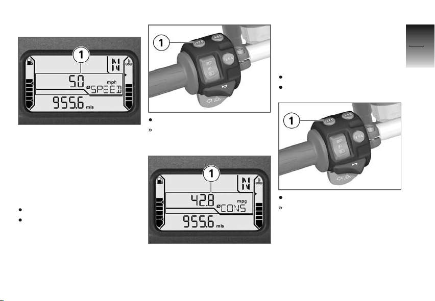
Ambient temperature
When the motorcycle is stopped,
the engine heat can falsify the
measurement of the ambient
temperature 1. If the influence
of the engine heat becomes too
great,
-- is temporarily shown in
the display.
If the ambient temperature
drops below 3 °C, a warning of possible icing-up appears.
The display automatically switches from any other mode to the
temperature reading when the
temperature drops below this
threshold for the first time.
Page 55
Average speed
The average speed 1 is calculated based on the elapsed
time since the last reset. Times
during which the engine was
stopped are excluded from the
calculation.
Resetting average speed
Switch on ignition.
Select average speed.
Hold down button 1.
Average speed is reset.
Average consumption
The average consumption 1 is
calculated by dividing the distance covered since the last re-
set by the corresponding amount
of fuel used.
Resetting average
consumption
Switch on ignition.
Select average consumption.
Hold down button 1.
Average consumption is reset.
4
53
z
Operation
Page 56
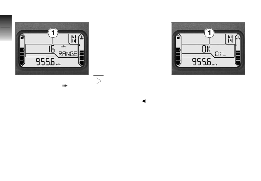
Range
4
54
The functional description of
the operating range ( 51) al-
z
Operation
so applies to the range. However, the range 1 can also be
displayed before the fuel reserve is reached. To calculate
the range, a special average consumption is used, which does not
always match the value that can
be shown on the display.
If the motorcycle is standing on
the side stand, the fuel level cannot be correctly determined due
to the inclined position. For this
reason the range is only calculated while driving.
When refueling after running on
reserve, make sure that you top
up the tank to a level above reserve, as otherwise the sensor
will not be able to register the
new level. Otherwise neither the
fill level nor the range display can
be updated.
The determined range is an
approximate reading. BMW
Motorrad therefore recommends
that you do not try to use the full
range before refueling.
Oil level indicator
The oil level indicator 1 provides
information on the oil level in the
engine. It can only be displayed
when the motorcycle is stopped.
The conditions for the oil level
indicator are as follows:
Engine at operating temperature.
Engine idling for at least 10
seconds.
Side-stand retracted.
Motorcycle is vertical.
Page 57
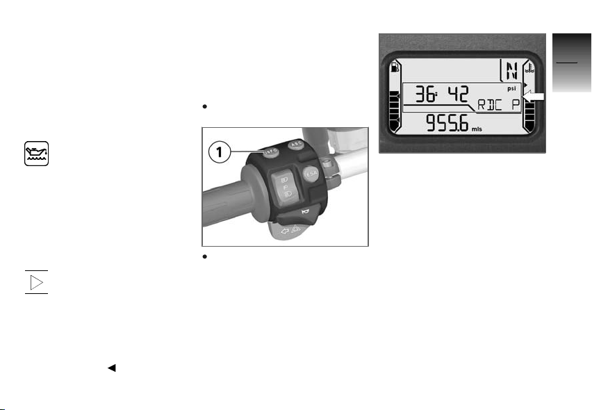
The readings mean:
OK: Oil level is correct.
CHECK: Check oil level during
next refueling stop.
---: No measurement possible
(above-mentioned conditions not
met).
If other information of the
onboard computer is displayed, this symbol continues to
be shown until the oil level is detected as correct again.
The most recently measured
level is displayed for 5 seconds
when you next switch on the ignition.
Should, despite a correct oil
level on the display of the
engine oil reservoir, "Check oil
level" appear continuously in the
display, the oil level sensor may
be defective. In this case, please
contact your authorized BMW
Motorrad retailer.
Tire Pressure Control
OE
RDC
Displaying tire inflation
pressure
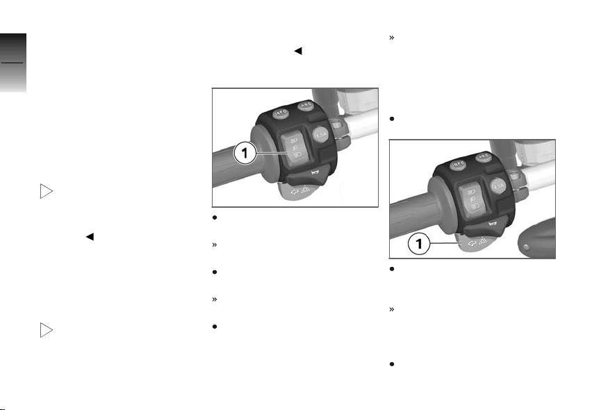
Switch on ignition.
Repeatedly press button 1 until the tire inflation pressures
appear in the display.
The tire inflation pressures are
displayed with the lettering
RDC P. The left-hand value
indicates the inflation pressure of
the front wheel, and the righthand value the inflation pressure
of the rear wheel. Immediately
after switching on the ignition,
-- -- is displayed, as the
transfer of the inflation pressure
values does not begin until a
speed over 20 mph (30 km/h) is
reached.
The display is shown alternately
with the clock.
4
55
z
Operation
Page 58
On motorcycles with an onboard
computer, the display appears in
4
alternation with the clock and the
56
values of the onboard computer.
Lights
Parking lights
The parking lights switch on automatically when the ignition is
switched on.
z
Operation
The parking lights are a
strain on the battery. Do
not leave the ignition switched
on longer than absolutely
necessary.
Low-beam headlight
The low-beam headlight switches
on automatically when you start
the engine.
With the engine switched
off, you can switch on the
lights by switching on the highbeam headlight with the ignition
switched on or by operating the
headlight flasher.
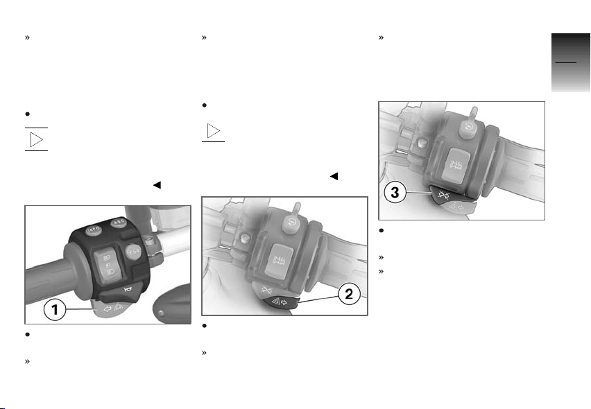
High-beam headlight
Press top section of full-beam
headlight switch 1.
High-beam headlight is
switched on.
Move full-beam headlight
switch 1 to center position.
High-beam headlight is
switched off.
Press bottom section of fullbeam headlight switch 1.
High-beam headlight is
switched on as long as switch
is pressed (headlight flasher).
Switching on parking
lights
Switch off ignition.
Immediately after switching off
ignition, press and hold lefthand turn indicator button 1.
Parking light switches on.
Switching off parking
lights
Switch ignition on and then off
again.
Page 59
Parking light switched off.
Turn indicators
Switching on left-hand
turn indicator
Switch on ignition.
After driving for approx.
ten seconds or after covering a distance of approx. 650
ft (200 m), the turn indicators are
automatically switched off.
Indicator light for left-hand turn
indicators flashes.
Switching on right-hand
turn indicator
Switch on ignition.
After driving for approx.
ten seconds or after covering a distance of approx. 650
ft (200 m), the turn indicators are
automatically switched off.
Indicator light for right-hand
turn indicators flashes.
Switching off turn
indicator
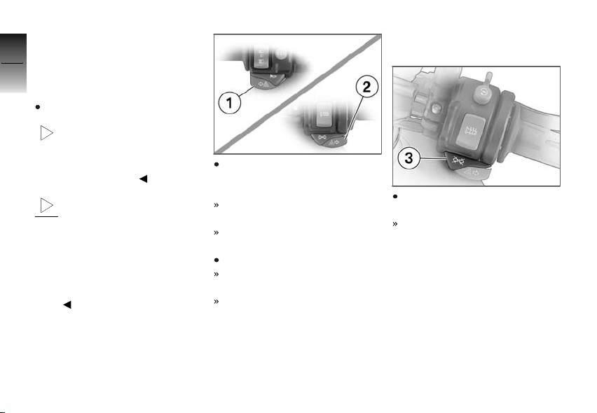
Press turn-indicator cancel button 3.
Turn indicator is switched off.
Indicator lights for turn indicators are off.
4
57
z
Operation
Press left-hand turn indicator
button 1.
Left-hand turn indicator is
switched on.
Press right-hand turn indicator
button 2.
Right-hand turn indicator is
switched on.
Page 60
Hazard warning
4
flashers
58
Switching on hazard
warning flashers
Switch on ignition.
The hazard warning flash-
ers place a strain on the
battery. Do not use the hazard
warning flashers for longer than
absolutely necessary.
z
Operation
If a turn indicator button is
pressed with the ignition
switched on, the flashing function
replaces the emergency flashing
function as long as the button is
pressed. If the turn indicator button is released, the emergency
flasher function becomes active
again.
Press left 1 and right-hand 2
turn indicator buttons simultaneously.
The hazard warning flashers
are switched on.
Indicator lights for left and right
turn indicator flash.
Switch off ignition.
Hazard warning flashers continue to operate.
Left/right turn indicator lights
off.
Switching off hazard
warning flashers
Press turn-indicator cancel button 3.
Hazard warning flashers are
switched off.
Page 61
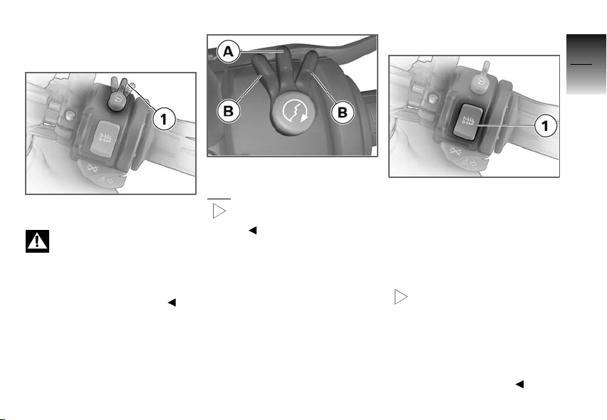
Emergency ON/OFF switch
1 Emergency ON/OFF switch
Operating the emergency
ON/OFF switch when riding
can cause the rear wheel to lock
and thus cause a fall.
Do not operate the emergency
ON/OFF switch when riding.
The engine can be switched
off easily and quickly using the
emergency ON/OFF switch.
A Operating position
B Engine switched off.
The engine can only be
started in the operating
position.
Heated hand grips
1 Heated hand grip switch
The handlebar grips can be heated at two different levels. The
heated hand grips option can only be activated when the engine
is running.
The increase in power con-
sumption caused by the
heated hand grips can drain the
battery if you are riding at low
engine speeds. If the battery is
inadequately charged, the heated hand grips are switched off to
ensure starting capability.
OE
4
59
z
Operation
Page 62
4
60
Activating ASC function
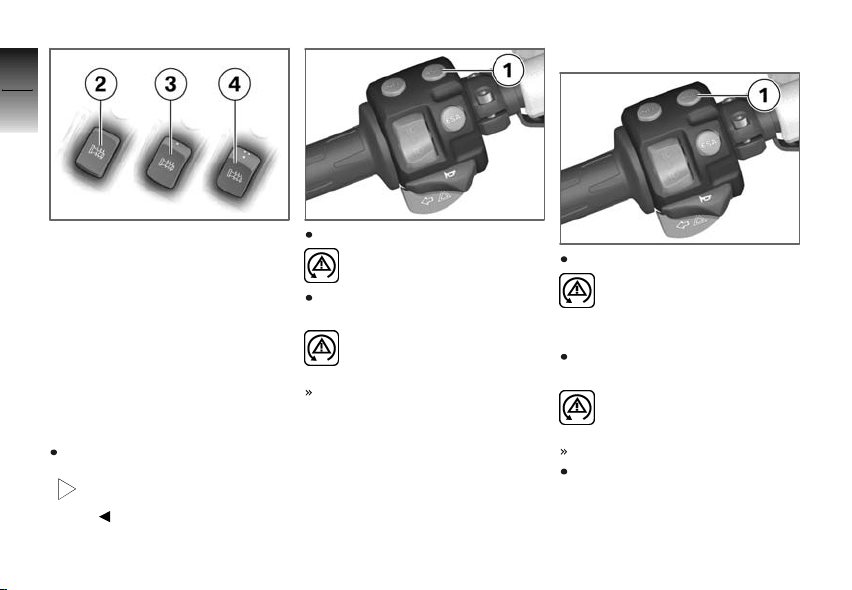
2 Heating function off.
3 50 % heat output (one dot
z
visible).
Operation
4 100 % heat output (three
dots visible).
Automatic Stability
Control ASC
Switching off ASC
function
Switch on ignition.
The ASC function can also be deactivated while
driving.
OE
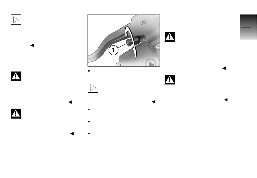
Press and hold ASC button 1.
ASC symbol is continuously
displayed.
Release ASC button within
three seconds.
ASC symbol continues to
be displayed.
ASC function is deactivated.
Press and hold ASC button 1.
ASC symbol is no longer
displayed; if self-diagnosis
is not completed, ASC warning
light begins to flash.
Release ASC button within
three seconds.
ASC symbol remains off or
continues to flash.
ASC function is activated.
As an alternative to pressing
the ASC button, the ignition
can also be switched off and
then on again.
Page 63
If the ASC warning light
lights up after switching
the ignition off and on and then
continued driving over 5 mph
(10 km/h), an ASC error has
occurred.
Clutch
Adjusting clutch lever
If the position of the clutch
fluid reservoir is changed,
air can enter the clutch system.
Do not reposition the handlebar
controls on the handlebars or the
handlebars in their mounts.
Adjusting the clutch lever
while driving can lead to
accidents.
Only adjust the clutch lever when
the motorcycle is stationary.
Turn adjusting screw 1 clockwise.
The adjusting screw has a
limit position and can be
turned more easily when you
press the clutch lever forward.
Distance between handlebar
grip and clutch lever increases.
Turn adjusting screw 1 counterclockwise.
Distance between handlebar
grip and clutch lever decreases.
Brakes
Adjusting handbrake lever
Changing the position of
the brake-fluid reservoir can
allow air to penetrate the brake
system.
Do not reposition the handlebar
controls on the handlebars or the
handlebars in their mounts.
Adjusting the brake lever
while driving can lead to
accidents.
Only adjust the brake lever when
the motorcycle is stationary.
4
61
z
Operation
Page 64
4
62
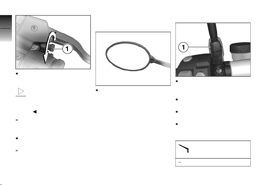
Turn adjusting screw 1 clockwise.
z
Operation
The adjusting screw has
a limit position and can
be turned more easily when
you press the handbrake lever
forward.
Distance between handlebar
grip and handbrake lever increases.
Turn adjusting screw 1 counterclockwise.
Distance between handlebar
grip and handbrake lever decreases.
Mirrors
Adjusting mirrors
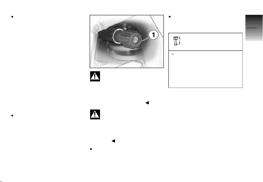
Move mirror into desired position by twisting.
Adjusting mirror arm
Slide up protective cap over
threaded fastener on mirror
arm.
Loosen nut 1 (left-hand
thread).
Turn mirror arm into desired
position.
Tighten nut 1 to specified
torque while holding mirror arm
in place.
Mirror on clamping piece
16 lb/ft (22 Nm)
Page 65
Slide protective cap over
threaded fastener.
Spring preload
Setting
It is essential to set spring
preload of the rear suspension
to suit the load carried by the
motorcycle. Increase spring
preload when the motorcycle is
heavily loaded and reduce spring
preload accordingly when the
motorcycle is lightly loaded.
Adjusting spring preload
for rear wheel
Make sure ground is level and
firm and park motorcycle.
Your motorcycle's han-
dling will suffer if you do
not match the spring-preload and
damping-characteristic settings.
Adjust the damping characteristic
to suit the spring preload.
Adjusting the spring preload
while the motorcycle is being ridden can lead to accidents.
Adjust the spring preload
only when the motorcycle is
stationary.
To increase spring preload,
turn handwheel 1 in direction
of arrow HIGH.
To decrease spring preload,
turn handwheel 1 in direction
of arrow LOW.
Basic setting of spring
preload, rear
Turn handwheel as far as
possible in direction of arrow
LOW, then turn 13 clicks
in direction of arrow HIGH
(Full tank of gas, with rider
187 lbs (85 kg))
Damping
Setting
The damping must be adapted to the spring preload. An increase in spring preload requires
firmer damping, a reduction in
spring preload requires softer
damping.
4
63
z
Operation
Page 66
Adjusting damping on rear
4
wheel
Make sure ground is level and
64
firm and park motorcycle.
z
Operation
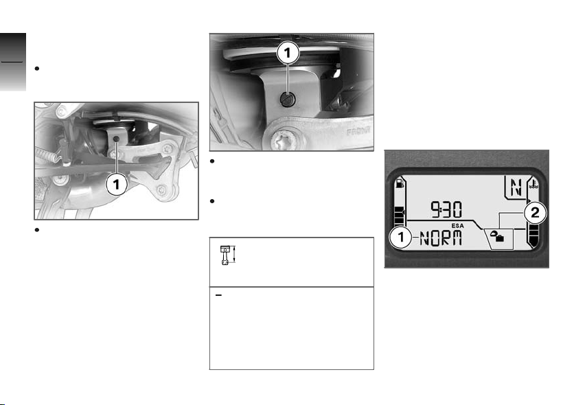
Adjust rear shock absorber
with toolkit by turning adjusting screw 1.
To increase damping, turn adjusting screw in direction of
arrow H.
To decrease damping, turn adjusting screw in direction of
arrow S.
Basic setting of rear
wheel rear-wheel damp-
ing
Turn adjusting screw as far
as possible in direction of
arrow H, then turn one and
one-half turn in direction of
arrow S (Single rider with
one person 187 lbs (85 kg))
Electronic suspension
adjustment ESA
Settings
Using the electronic suspension
adjustment ESA you can conveniently adjust your motorcycle to
its loading and the ground.
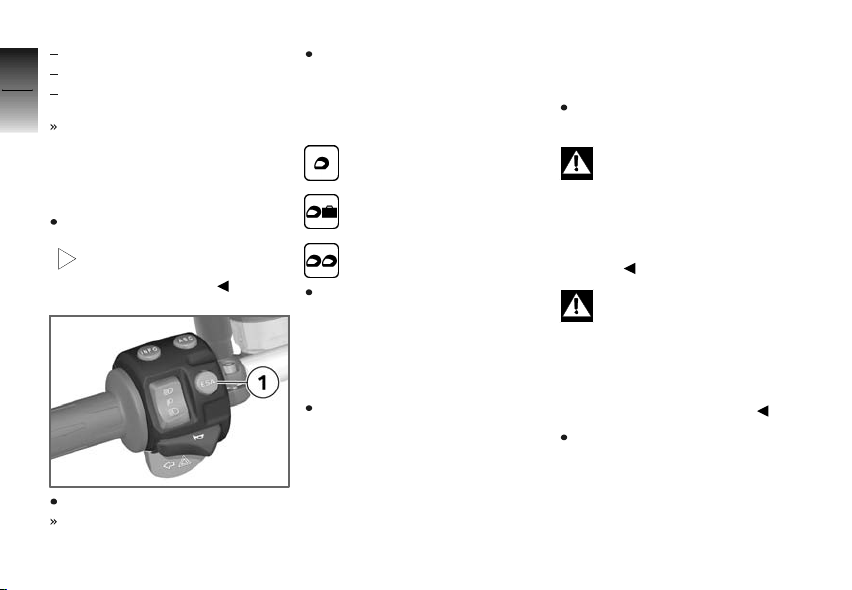
The damping setting is shown in
the multifunction display in the
area 1, and the spring preload
in the area 2. The display of the
odometer is hidden as long as
the ESA display is shown. Three
spring preloads with three damping setting each can be com-
OE
Page 67

bined to optimally adjust the motorcycle.
Adjusting spring preload
The ESA control unit is equipped
with an overload protection
device that interrupts the
adjustment process for the spring
preload in case of excessive
current consumption. Especially
at low temperatures and with a
heavy payload, increased current
consumption can briefly result,
causing an interruption of the
adjustment process.
At temperatures below 0 °C,
BMW Motorrad recommends
that the passenger should wait
until the adjustment process to
passenger mode is completed
before taking a seat. In case of
very long adjustment distances
(adjustment from "single rider"
to "operation with passenger and
luggage"), BMW Motorrad also
recommends unloading the motorcycle.
The ESA display flashes until the
adjustment process has been
completed.
An interrupted adjustment process is automatically continued
as soon as the current consumption is reduced, e.g. with the
measures described above.
Calling up settings
Switch on ignition.
Press button 1.
The current setting is
displayed.
Display goes out automatically
after a few seconds.
Adjusting damping
Switch on ignition.
The damping cannot be adjusted while the motorcycle
is being ridden.
Press button 1.
Current setting is displayed.
Press button 1 once in each
case.
Starting from the current state,
the display is in the following order:
4
65
z
Operation
Page 68
COMF: comfortable damping
NORM: normal damping
4
SPORT: sporty damping
66
If no further changes are made,
the damping is adjusted as indicated.
Adjusting spring preload
Start engine.
The spring preload cannot
z
Operation
be adjusted while the mo-
torcycle is being ridden.
Press button 1.
Current setting is displayed.
Press and hold button 1 until
display changes each time.
Starting from the current state,
the display is in the following order:
One-up
One-up with luggage
Two-up (with luggage)
If no further changes are made,
the spring preload and, if nec-
essary, the damping is/are ad-
justed as indicated. The dis-
play flashes while the spring
preload is adjusted.
Wait for the adjustment
process to be completed
before continuing driving
(display flashes).
Tires
Checking tire pressure
Make sure ground is level and
firm and park motorcycle.
Incorrect tire inflation pres-
sure results in poorer handing characteristics of the motorcycle and reduces the life of the
tires.
Ensure proper tire inflation
pressure.
At high road speeds, tire
valves have a tendency to
open as a result of centrifugal
force.
Fit metal valve caps with rubber
seals and screw them on firmly
to prevent sudden deflation.
Check correct tire inflation
pressure using following data.
Page 69
Tire pressure, front
36.3 psi (2.5 bar) (Single rider, with cold tire)
36.3 psi (2.5 bar) (Driver with
passenger and/or load, with
cold tire)
Tire pressure, rear
42.1 psi (2.9 bar) (Single rider, with cold tire)
42.1 psi (2.9 bar) (Driver with
passenger and/or load, with
cold tire)
If tire pressure is too low:
Correct tire pressure.
Headlight
Adjusting headlight for
RHD/LHD traffic
If the motorcycle is ridden in a
country where the opposite rule
of the road applies, its asymmetric low-beam headlight will tend
to dazzle oncoming traffic.
Have the headlight adjusted to
the relevant conditions by a specialized workshop, preferably an
authorized BMW Motorrad retailer.
Ordinary adhesive tape
damages the plastic lens.
To prevent damage to the plastic
lens, consult a specialized workshop, preferably an authorized
BMW Motorrad retailer.
Headlight range and
spring preload
The headlight range remains
constant due to the adjustment
of the spring preload to the loading state.
If you are unsure whether
the basic headlight setting
is correct, consult a specialized
workshop, preferably an authorized BMW Motorrad retailer.
Seat
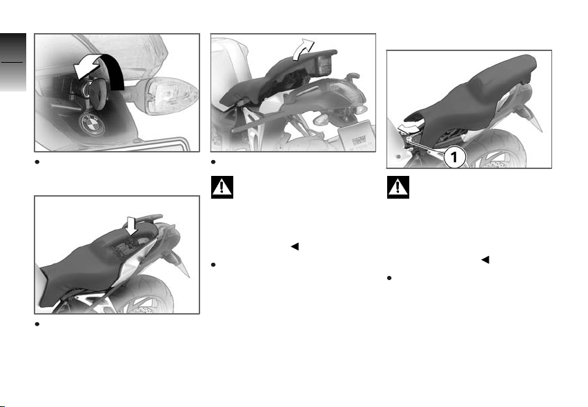
Removing seat
Make sure ground is level and
firm and park motorcycle.
4
67
z
Operation
Page 70
4
68
Installing seat
Turn the key counterclockwise
in the seat lock.
z
Operation
When doing so, press the seat
downwards for support.
Raise the seat at the rear.
If seat is laid on a rough
surface, seat edges can be
damaged.
Lay the seat on the reference
side on a smooth, clean surface,
e.g. on the tank.
Let go of the key and pull the
seat from the retaining bracket
towards the rear.
If too much pressure is ap-
plied in the forward direction, there is a danger that the
motorcycle will be pushed off its
stand.
Make sure that the motorcycle is
steady on its stand.
Push seat forward into retaining
brackets 1.
Page 71
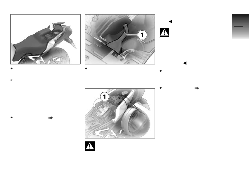
Press the seat firmly downwards beyond the detent.
The seat can be heard to lock
into place.
Helmet holder
Locking helmet on
motorcycle
Removing seat ( 67)
Secure helmet on helmet holder 1 using steel cable available
as an optional accessory.
The helmet catch can
scratch the paneling.
When hooking on the helmet,
watch the position of the helmet
lock.
On the right-hand side of
the motorcycle, the helmet
could be damaged by heat from
the end muffler.
Only attach the helmet to
the left-hand side of the
motorcycle.
To do this, guide steel cable
through helmet and push cable
eyes onto holder.
Installing seat ( 68)
4
69
z
Operation
Page 72
Luggage loops
4
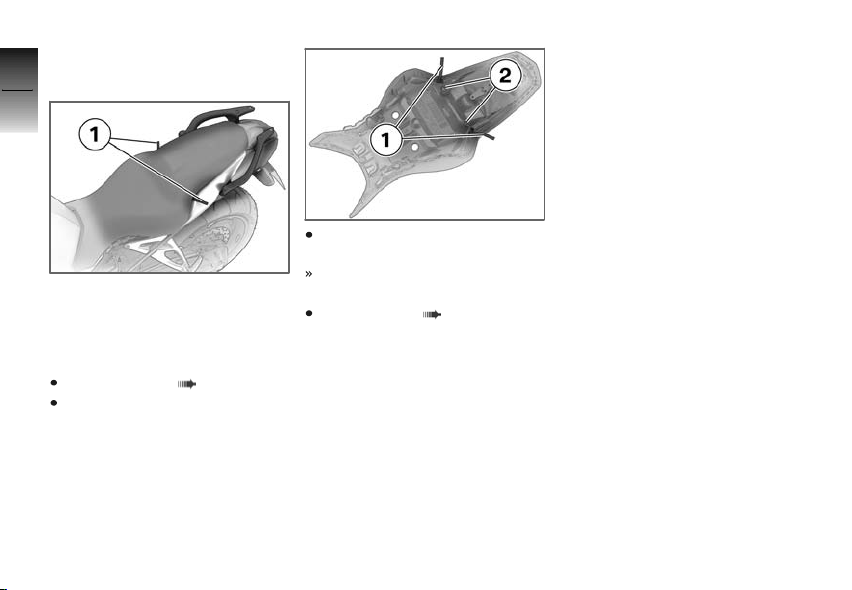
Luggage loops under seat
70
z
Operation
The loops 1 for attaching luggage straps are located on the
underside of the seat.
Using luggage straps
Removing seat ( 67)
Turn over seat.
Pull loops 1 out of retaining
brackets 2.
Luggage straps can be hooked
into loops.
Installing seat ( 68)
Page 73

Riding
Safety instructions ................... 72
Checklist............................. 73
Starting .............................. 74
Running in ........................... 77
Brakes ............................... 78
Parking your motorcycle . ............ 79
Refueling ............................ 80
5
71
z
Riding
Page 74
Safety instructions
5
Rider's equipment
72
Do not ride without the correct
clothing. Always wear:
Helmet
Rider's suit
Gloves
Boots
This applies even to short jour-
z
Riding
neys, and to every season of the
year. Your authorized BMW Motorrad retailer will be happy to
advise you and has the correct
clothing for every purpose.
Speed
If you ride at high speed, always
bear in mind that various boundary conditions can adversely affect the handling of your motorcycle:
Settings of spring-strut and
shock absorber system
Imbalanced load
Loose clothing
Insufficient tire inflation pressure
Poor tire tread
Etc.
Correct loading
Overloading and imbal-
anced loads can adversely
affect the motorcycle's handling.
Do not exceed the gross weight
limit and observe the loading
information.
Alcohol and drugs
Even small amounts of al-
cohol or drugs will adversely affect your perception and your
ability to assess situations and
make decisions, and slow down
your reflexes. Medication can exacerbate these effects.
Do not ride your motorcycle after
consuming alcohol, drugs and/or
medication.
Risk of poisoning
Exhaust fumes contain carbon
monoxide, which is colorless and
odorless but highly toxic.
Inhaling exhaust fumes
therefore represents a
health hazard and can even
cause loss of consciousness with
fatal consequences.
Do not inhale exhaust fumes.
Do not run the engine in closed
rooms.
High voltage
Touching live parts of the
ignition system with the
engine running can cause electric
shock.
Do not touch parts of the ignition system when the engine is
running.
Page 75
Catalytic converter
If misfiring causes unburned fuel
to enter the catalytic converter,
there is a danger of overheating
and damage.
For this reason, observe the following points:
Do not run the fuel tank dry
Do not run the engine with the
spark-plug cap removed
Stop the engine immediately if
it misfires
Use unleaded fuel only
Comply with all specified maintenance intervals.
Unburned fuel will destroy
the catalytic converter.
Note the points listed for protection of the catalytic converter.
Risk of fire
Temperatures at the exhaust are
high.
Flammable materials (e.g.
hay, leaves, grass, clothing
and luggage, etc.) could ignite
if allowed to come into contact
with the hot exhaust pipe.
Make sure that no highly
flammable materials can come
in contact with the hot exhaust
system.
Cooling would be inade-
quate if the engine were allowed to idle for a lengthy period
with the motorcycle at a standstill: overheating would result. In
extreme cases, the motorcycle
could catch fire.
Do not allow the engine to idle
unnecessarily. After starting, ride
off immediately.
Tampering with control
unit of electronic enginemanagement system
Tampering with the engine
control unit can damage
the motorcycle and cause accidents.
Do not tamper with the engine
control unit.
Tampering with the engine
control unit can result in
mechanical loads that the motorcycle's components are not
designed to withstand. Damage
caused in this way is not covered
by the warranty.
Do not tamper with the engine
control unit.
Checklist
Use the following checklist to
check important functions, settings and wear limits before you
ride off.
5
73
z
Riding
Page 76
Brakes
Front and rear brake fluid levels
5
Clutch
74
Clutch fluid level
Shock absorber setting and
spring preload
Tread depth and tire inflation
pressure
Firm seating of cases and luggage
z
Riding
At regular intervals:
Engine oil level (every time you
refuel)
Brake pad wear (during every
third stop for refueling)
Starting
Side stand
You cannot start the motorcycle with the side stand extended
and a gear engaged. The engine
will switch itself off if you start it
with the transmission in neutral
and then engage a gear before
retracting the side stand.
Transmission
You can start the engine when
the transmission is in neutral or if
you pull the clutch with a gear
engaged. Do not engage the
clutch until after switching on
the ignition, as otherwise the engine cannot be started. When
the transmission is in neutral, the
green neutral indicator light is on
and the gear indicator in the multifunction display shows N.
Starting engine
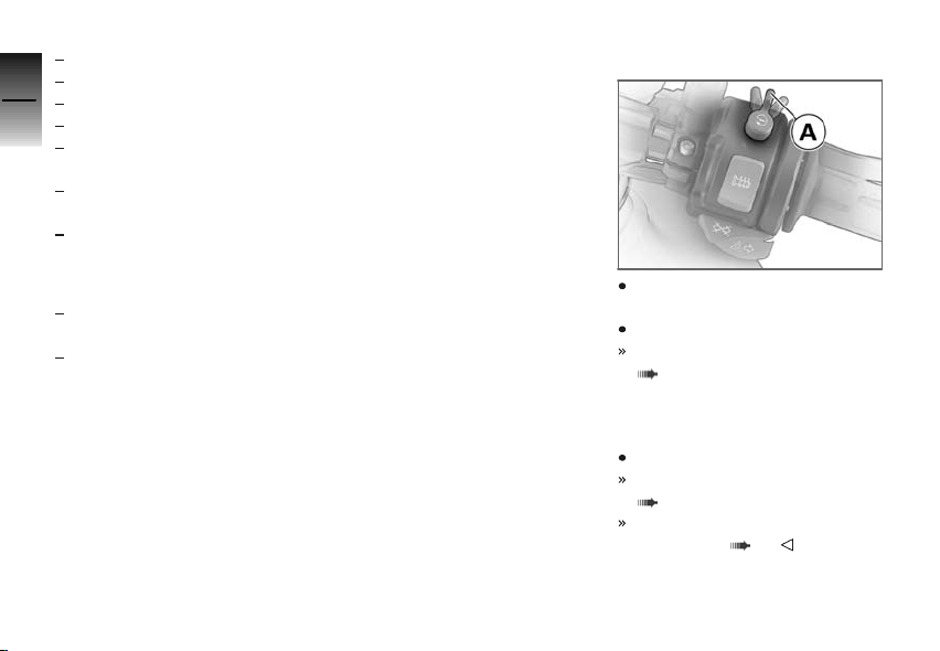
Emergency ON/OFF switch in
operating position A.
Switch on ignition.
Pre-ride check is performed.
( 75)
With OE BMW Motorrad Integral
ABS:
Switch on ignition.
Pre-ride check is performed.
( 75)
ABS self-diagnosis is
performed. ( 76)
Page 77
With OE Automatic Stability
Control (ASC):
Switch on ignition.
Pre-ride check is performed.
( 75)
ABS self-diagnosis is
performed. ( 76)
ASC self-diagnosis is performed. ( 76)
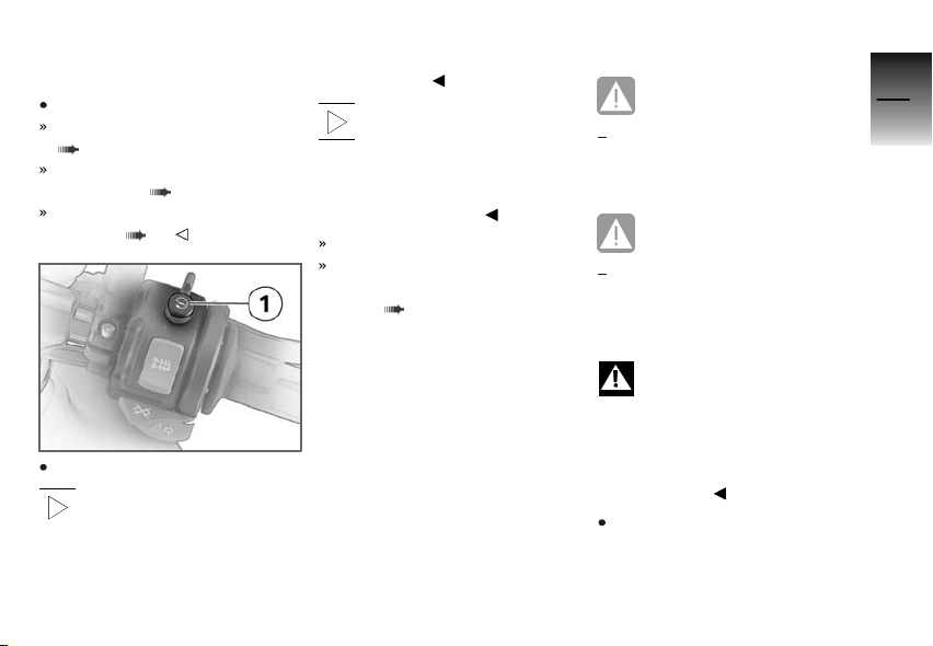
Press starter button 1.
At extremely low tempera-
tures it may be necessary
to operate the throttle twist grip
during starting. At ambient temperatures below 32 °F (0 °C),
actuate the clutch after switching
on the ignition.
The start attempt is auto-
matically interrupted if battery voltage is too low. Recharge
the battery before you start the
engine, or use jump leads and a
donor battery to start.
Engine starts.
Consult the troubleshooting
chart if the engine refuses to
start. ( 134)
Pre-ride check
The instrument cluster runs a
test of the 'General' warning light
when the ignition is switched on:
this is the "Pre-Ride-Check" In
the process, the warning light
first lights up red and then yellow
to test its function. The test is
aborted if you start the engine
before it completes.
Phase 1
General warning light shows
red.
CHECK! appears on the dis-
play.
Phase 2
General warning light shows
yellow.
CHECK! appears on the dis-
play.
If the 'General' warning light does
not show:
Some malfunctions cannot
be indicated if the 'General' warning light cannot be displayed.
Check that the 'General' warning
light comes on, and that it shows
red and yellow.
Have the malfunction corrected
as soon as possible by a specialized workshop, preferably
5
75
z
Riding
Page 78
an authorized BMW Motorrad
retailer.
5
76
ABS self-diagnosis
The readiness for operation
of the BMW Motorrad ABS is
checked by the self-diagnosis.
Self-diagnosis is performed
automatically when you switch on
the ignition. To check the wheel
sensors, the motorcycle must
z
Riding
drive faster than 3 mph (5 km/h).
Phase 1
Checking diagnosable system
components while stopped.
ABS warning light flashes.
Possible country-specific version of ABS warning
light.
Phase 2
Checking wheel sensors while
starting off.
OE
ABS warning light flashes.
Possible country-specific version of ABS warning
light.
ABS self-diagnosis
completed
The ABS warning light goes
out.
If an ABS fault is indicated after
the ABS self-diagnosis is completed:
Continue driving is possible. It
must be noted that neither the
ABS nor the integral function is
available.
Have the malfunction corrected
as soon as possible by a spe-
cialized workshop, preferably
an authorized BMW Motorrad
retailer.
ASC self-diagnosis
The readiness for operation
of the BMW Motorrad ASC is
OE
checked by the self-diagnosis.
Self-diagnosis is performed
automatically when you switch
on the ignition. So that the ASC
self-diagnosis can be completed,
the engine must be running and
the motorcycle must drive at a
speed of at least 3 mph (5 km/h).
Phase 1
Checking diagnosable system
components while stopped.
ASC symbol flashes.
Phase 2
Checking diagnosable system
components while driving.
ASC symbol flashes.
ASC self-diagnosis
completed
ASC warning light goes out.
Page 79
If an ASC fault is indicated after
the ASC self-diagnosis is completed:
Continue driving is possible. It
must be noted that the ASC
function is not available.
Have the malfunction corrected
as soon as possible by a specialized workshop, preferably
an authorized BMW Motorrad
retailer.
Running in
The first 600 miles
(1,000 km)
While running in the motorcycle, vary the throttle opening
and engine-speed range frequently.
Try to do most of your riding during this initial period on
twisting, fairly hilly roads, avoiding high-speed main roads and
highways if possible.
Exceeding the specified en-
gine speeds while running
in will lead to increased engine
wear.
Adhere to the specified engine
run-in speeds.
Do not exceed the engine runin speeds.
Engine break-in speed
<7000 min
Do not accelerate at full throttle.
Avoid low engine speeds at full
load.
After 300 - 750 miles (500 1,200 km), have the first inspection performed.
-1
Brake pads
New brake pads must "bed
down" and therefore do not
achieve their optimum friction
levels during the first 300 miles
(500 km). This initial reduction
in braking efficiency can be
compensated for by exerting
greater pressure on the levers.
New brake pads can ex-
tend stopping distance by a
significant margin.
Brake early.
Tires
New tires have a smooth surface. This must be roughened by
riding in a restrained manner at
various heel angles until the tires
are run in. This running in procedure is essential if the tires are to
achieve maximum grip.
New tires have not
achieved their full adhesion
yet. There is a danger of
accidents when driving at
extreme angles.
Avoid extreme angles.
5
77
z
Riding
Page 80

Brakes
5
How is the shortest
78
braking distance
achieved?
The dynamic load distribution
between the front and rear wheel
changes during braking. The
heavier you brake, the more
the front wheel is loaded. The
z
Riding
greater the wheel load, the more
braking force can be transferred.
To achieve the shortest possible
braking distance, the front brake
must be applied quickly and with
increasing force. This optimally utilizes the dynamic load increase on the front wheel. At the
same time, the clutch should also be actuated. With the "forced
braking" often practiced in which
the brake pressure is generated as quickly as possible and
with great force, the dynamic
load distribution cannot follow
the increased deceleration and
the braking force cannot be completely transferred to the road
surface. To prevent the front
wheel from locking, the ABS system must intervene and reduce
the brake pressure; the braking
distance increases.
Descending mountain
passes
There is a danger of the
brakes fading if you use only the rear brakes when descending mountain passes. Under
extreme conditions, the brakes
could overheat and suffer severe
damage.
Use both front and rear brakes,
and make use of the engine's
braking effect as well.
Wet brakes
After washing the motor-
cycle, after driving through
water or in the rain, braking can
be delayed due to damp brake
disks and brake pads.
Brake early until the brakes are
dry or braked until dry.
Salt on brakes
The full braking effect can
be delayed if the motorcycle is ridden on salt-covered
roads and the brakes are not applied for some time.
Brake early until the salt layer of
the brake disks and brake pads
has been braked off.
Oil or grease on brakes
Oil and grease on the brake
disks and pads considerably
diminish braking efficiency.
Especially after repair and maintenance tasks, make sure that
the brake disks and brake pads
are free of oil and grease.
Page 81
Dirt or mud on brakes
When the motorcycle is
ridden on loose surfaces
or muddy roads, the brakes may
fail to take effect immediately
because of dirt or moisture on
the disks or brake pads.
Brake early until the brakes are
braked clean.
Parking your motorcycle
Placing on side stand
If the ground is soft or un-
even, there is no guarantee
that the motorcycle will rest firmly on the stand.
Always check that the ground
under the stand is level and
firm.
Switch off the engine.
Pull handbrake lever.
Hold motorcycle upright and
balanced.
Use your left foot to extend
side stand fully.
The side stand is designed
to support only the weight
of the motorcycle.
Do not lean or sit on the
motorcycle with the side stand
extended.
Slowly lean motorcycle to side
until its weight is taken by
stand and dismount to left.
If the motorcycle is on the
side stand, the surface
of the ground will determine
whether it is better to turn the
handlebars to the left or right.
However, the motorcycle is more
stable on a level surface with the
handlebars turned to the left than
with the handlebars turned to the
right.
On level ground, always turn the
handlebars to the left to set the
steering lock.
Turn handlebars to full left or
right lock position.
Check that motorcycle is
standing firmly.
On a grade, the motorcycle
should always face uphill;
select 1st gear.
Lock steering lock.
Remove from side stand
Unlock steering lock.
From left, grip handlebars with
both hands.
Pull handbrake lever.
Swing your right leg over the
seat and lift motorcycle to upright position.
Hold motorcycle upright and
balanced.
An extended side stand can
catch on the ground when
the motorcycle is moving and
lead to a fall.
Retract the side stand before
moving the vehicle.
5
79
z
Riding
Page 82

Sit on motorcycle and use your
left foot to retract side stand.
5
80
Placing on center stand
If the ground is soft or un-
even, there is no guarantee
that the motorcycle will rest firmly on the stand.
Always check that the ground
under the stand is level and
z
Riding
firm.
Switch off the engine.
Dismount and keep your left
hand on left handlebar grip.
Grasp passenger seat handle
or rear frame with your right
hand.
Place right foot on extended
arm of center stand, and press
stand down until its curved feet
touch ground.
Place full weight of body on
center stand while pulling motorcycle toward rear.
Excessive movements
could result in the center
stand retracting, and the
OA
motorcycle would topple as a
result.
Do not sit on the motorcycle
while it is resting on the center
stand.
Check that the motorcycle is
standing firmly.
Lock steering lock.
Pushing off center
OA
stand
Unlock steering lock.
Place your left hand on left
handlebar grip.
With your right hand, grip rear
grab handle or rear frame.
Push motorcycle forward off
center stand.
Make sure that center stand is
fully retracted.
Refueling
Fuel is highly flammable.
Fire at the fuel tank can
result in fire and explosion.
Do not smoke. Never bring a
naked flame near the fuel tank.
Fuel expands when ex-
posed to heat. When the
tank is overfilled, fuel can escape
and get onto the rear wheel.
This results in a danger of falling.
Do not fill the tank past the bottom edge of the filler neck.
Fuel attacks plastic sur-
faces, making them cloudy
or unattractive.
Wipe off any fuel that gets onto
plastic parts immediately.
Fuel can attack the material
of the windshield; it then
becomes dull or unsightly.
Wipe off any fuel that gets onto
the windshield immediately.
Page 83
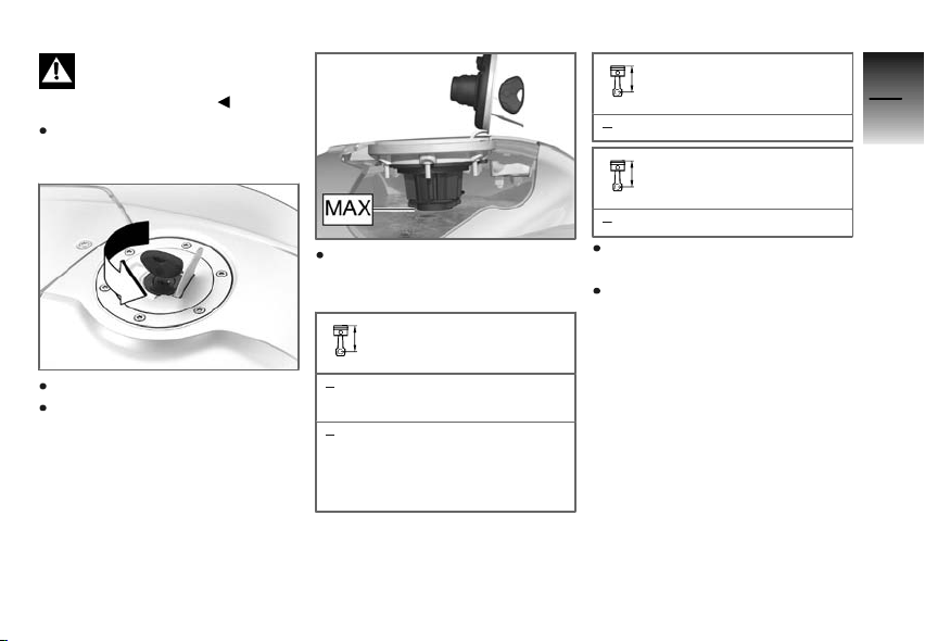
Leaded fuel will destroy the
catalytic converter.
Use only unleaded fuel.
Make sure ground is level and
firm and park motorcycle.
Open protective cap.
Open fuel tank cap with ignition key by turning it counterclockwise.
Refuel with quality listed below
at most until lower edge of filler
neck is reached.
Recommended fuel quality
98 ROZ/RON (Super Plus
unleaded)
95 ROZ/RON (Super unleaded (fuel type can be used
with reduced performance
and consumption))
Usable fuel quantity
5 gal (19 l)
Reserve fuel quantity
≥1.1 gal (≥4l)
Press fuel tank cap down firmly
to close.
Remove key and close protective cap.
5
81
z
Riding
Page 84

5
82
z
Riding
Page 85

Technology in detail
Brake system with BMW Motorrad
Integral ABSOE...................... 84
Engine management with BMW Motorrad ASC
Tire Pressure Control RDCOE....... 87
OE
........................ 86
6
83
z
Technology in detail
Page 86

Brake system with
6
BMW Motorrad Integral
OE
ABS
84
Partially integral brake
Your motorcycle is equipped with
a partially integral brake configuration. Both front and rear brakes
are applied simultaneously when
you pull the handbrake lever.
The footbrake lever acts only on
the rear brake.
The BMW Motorrad Integral ABS
adapts the braking force distribution between the front and rear
wheel brake to the loading of the
motorcycle during braking.
z
Technology in detail
Spinning of the rear wheel
with the front brake pulled
(burn out) is made considerably more difficult by the integral function. The result may be
damage to the rear wheel brake
and the clutch.
Avoid burn-outs.
How does ABS work?
The maximum braking force that
can be transferred to the road
surface is partially dependent on
the friction coefficient of the road
surface. Gravel, ice, snow and
wet roads offer a considerably
poorer friction coefficient than a
dry, clean asphalt surface. The
poorer the friction coefficient of
the road surface is, the longer
the braking distance will be.
If the maximum transferrable
braking force is exceeded when
the driver increases the brake
pressure, the wheels begin to
block and driving stability is lost,
and a fall can result. Before this
situation occurs, ABS intervenes
and adjusts the brake pressure
to the maximum transferrable
braking force. This enables the
wheels to continue to turn and
maintains driving stability regardless of the road surface condition.
What happens when
rough roads are
encountered?
Bumpy or rough roads can briefly
lead to a loss of contact between the tires and the road
surface, until the transferrable
braking force is reduced to zero. If braking is carried out in this
situation, ABS must reduce the
brake pressure to ensure driving stability when restoring contact to the road. At this point in
time, the BMW Motorrad Integral
ABS must assume extremely low
friction coefficients (gravel, ice,
snow) so that the running wheels
turn in every imaginable case and
the driving stability is ensured.
After detecting the actual conditions, the system adjusts the
optimum brake pressure.
Page 87

How is the BMW Motorrad
Integral ABS noticeable to
the rider?
If the ABS system must reduce
the braking forces due to the
conditions described above, then
vibrations can be felt at the handbrake lever.
If the handbrake lever is pulled,
then braking pressure is built up
at the rear wheel with the integral
function. If the footbrake pedal is
first actuated after this, the brake
pressure already built up can be
felt earlier than the counter-pressure, than when the footbrake
pedal is actuated before or together with the handbrake lever.
Lifting off rear wheel
Even during severe braking, a
high level of tire grip can mean
that the front wheel does not
lock up until very late, if at all.
Consequently, ABS does not intervene until very late, if at all.
Under these circumstances the
rear wheel can lift off the ground,
and the outcome can be a highsiding situation in which the motorcycle can flip over.
Heavy braking can lead to
the rear wheel lifting off the
ground.
When braking, bear in mind that
the ABS control cannot be relied
on in all circumstances to prevent
the rear wheel from lifting off the
ground.
What are the design
characteristics of the
BMW Motorrad Integral
ABS?
The BMW Motorrad Integral ABS
ensures driving stability on any
surface within the limits of driving
physics. The system is not optimized for special requirements
resulting under extreme weath-
er conditions offroad or on the
racetrack.
Special situations
To detect the tendency of the
wheels to lock up, the speeds
of the front and rear wheel are
compared. If implausible values
are detected over a longer period
of time, the ABS function is deactivated for safety reasons and
an ABS fault is indicated. The
condition for a fault message is
the completed self-diagnosis.
In addition to problems on the
BMW Motorrad Integral ABS,
unusual driving conditions can
also lead to a fault message.
Unusual driving conditions:
Heating up on the main or auxiliary stand at idle or with gear
engaged.
Rear wheel locked-up for a
longer period of time by en-
6
85
z
Technology in detail
Page 88

gine brake, e.g. when riding
downhill offroad.
6
86
Should a fault message result
due to one of the driving conditions described above, the ABS
function can be reactivated by
switching the ignition off and
then on again.
How important is regular
maintenance?
Any technical system is al-
ways only as good as its
maintenance condition.
To ensure that the BMW Motorrad ABS is in an optimally maintained condition, it is vital that the
z
Technology in detail
specified inspection intervals be
complied with.
Reserves for safety
But remember: the potentially
shorter braking distances which
BMW Motorrad Integral ABS permits must not be used as an ex-
cuse for careless riding. ABS is
primarily a means of ensuring a
safety margin in genuine emergencies.
Take care when cornering. When
you apply the brakes on a corner, the motorcycle's weight and
momentum take over and even
BMW Motorrad Integral ABS is
unable to counteract their effects.
Engine management
with BMW Motorrad
OE
ASC
How does ASC work?
The BMW Motorrad ASC compares the wheel speeds of the
front and rear wheel. From the
speed difference the slip, and
with it the stability reserves on
the rear wheel are determined.
When a slip limit is exceeded, the
engine torque is adapted by the
engine management system.
What are the design
characteristics of the
BMW Motorrad ASC?
The BMW Motorrad ASC is an
assistance system for the driver and is designed for driving on
public roads. Especially in at the
limits of driving physics, the driver has a considerable influence
on the control options of the
ASC (shifting weight in curves,
loose loads). The system is not
optimized for special requirements resulting under extreme
weather conditions offroad or on
the racetrack. The BMW Motorrad ASC can be deactivated for
these cases.
Even with ASC, physical
laws cannot be overridden.
The driver is always responsible
for adapting his/her driving style.
Do not reduce the additional
safety provided with risky
driving.
Page 89

Special situations
At an increasing angle, the acceleration performance is increasingly limited in accordance with
physical laws. This can result in
delayed acceleration when coming out of very tight curves.
To detect spinning or slipping
away of the rear wheel, the
speeds of the front and
rear wheel are compared. If
implausible values are detected
over a longer period of time, the
ASC function is deactivated for
safety reasons and an ASC fault
is indicated. The condition for a
fault message is the completed
self-diagnosis.
In the following unusual driving
states, the BMW Motorrad ASC
can be automatically deactivated.
Unusual driving conditions:
Driving on the rear wheel
(wheely) for a longer period
with ASC deactivated.
Rear wheel spinning in place
with front brake pulled (burn
out).
Heating up on the main or auxiliary stand at idle or with gear
engaged.
The ASC is reactivated by
switching the ignition on and
off and then driving at a speed
above 10 km/h.
If the front wheel loses contact
to the ground during extreme
acceleration, the ASC reduces
the engine torque until the front
wheel touches the ground again.
In this case, BMW Motorrad
recommends turning back the
throttle twist grip somewhat to
achieve a stable driving state
again as quickly as possible.
On a slippery surface, the throttle
twist grip should never be suddenly turned back completely
without pull the clutch at the
same time. The engine braking
torque can cause the rear wheel
to block, resulting in an unstable
driving state. This case cannot
be controlled by the BWM Motorrad ASC.
Tire Pressure Control
OE
RDC
Function
A sensor is located in each tire,
which measures the air temperature and the inflation pressure
inside the tire and sends these
values to the control unit.
The sensors are equipped with
a centrifugal controller, which
does not enable the transmission of the measured values until a speed of approx. 20 mph
(30 km/h) is reached. Before initial reception of the tire inflation
pressure,
play for each tire. The sensors
continue to transmit the mea-
-- is shown in the dis-
6
87
z
Technology in detail
Page 90

sured values for approx. 15 minutes after the motorcycle comes
6
to a stop.
88
The control unit can manage four
sensors, and as a result two sets
of wheels with RDC sensors can
be driven. If a RDC control unit
is installed, however the wheels
have no sensors, then an error
message is output.
Temperature
compensation
The tire inflation pressures are
shown temperature-compensated in the multifunction display;
they refer to a tire air temperature of 68 °F (20 °C). As the air-
z
Technology in detail
pressure testers at filling stations
show a temperature-dependent
tire inflation pressure, they do
not match the values indicated in
the multifunction display in most
cases.
Tire inflation pressure
ranges
The RDC control unit distinguishes between three tire inflation
pressure ranges matched to the
motorcycle:
Inflation pressure within the
permissible tolerance.
Inflation pressure at the limits
of the permissible tolerance.
Inflation pressure outside the
permissible tolerance.
Page 91

Accessories
General instructions .................. 90
Onboard socket ...................... 90
Luggage ............................. 91
CaseOA.............................. 92
7
89
z
Accessories
Page 92
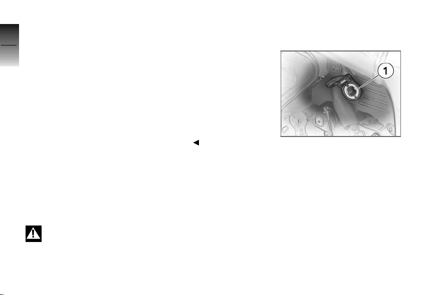
General instructions
7
BMW Motorrad recommends
the use of parts and accessories
90
for your motorcycle that are approved by BMW for this purpose.
Your authorized BMW Motorrad
retailer is the right place to go
for genuine BMW parts and accessories,other BMW-approved
products, and expert advice on
their installation and use.
These parts and products have
been tested by BMW for safety,
z
Accessories
function and suitability. BMW
accepts product liability for these
products.
Conversely, BMW is unable to
accept any liability whatsoever
for parts and accessories which it
has not approved.
BMW Motorrad cannot ex-
amine or test each product
of outside origin to ensure that it
can be used on or in connection
with BMW motorcycles without
constituting a safety hazard. Nor
is this guarantee provided when
the official approval of a specific
country has been granted. Tests
conducted by these instances
cannot make provision for all operating conditions experienced by
BMW motorcycles and, consequently, they are not sufficient in
some circumstances.
Use only parts and accessories
approved by BMW for your
motorcycle.
Whenever you are planning modifications, comply with all the legal requirements. The motorcycle must not infringe on national
road-vehicle construction and
use regulations.
Onboard socket
Ratings
When the battery voltage is insufficient, and when the maximum loading capacity of the
standard onboard socket 1 and
the additional socket (OE) is exceeded, these sockets are automatically switched off.
Operating electrical
accessories
You can start using electrical accessories only when the ignition
is switched on. The accessory
remains operational if the igni-
Page 93
tion is subsequently switched off.
Approx. 15 minutes after switching off the ignition and/or during
starting, the onboard socket is
switched off to take the load off
the motorcycle electrical system.
Cable routing
The cables from the onboard
socket to the auxiliary device
must be routed in such a way
that they:
Do not impede the rider
Do not restrict or obstruct the
steering angle and handling
characteristics
Cannot be trapped
Improperly routed cables
can impede the rider.
Route the cables as described
above.
Luggage
Correct loading
Overloading and imbal-
anced loads can adversely
affect the motorcycle's handling.
Do not exceed the gross weight
limit and observe the loading
information.
Adjust setting of spring
preload, damping characteristic
and tire inflation pressures to
suit total weight.
Adjusting spring preload for
rear wheel ( 63)
Checking tire pressure ( 66)
Adjusting damping on rear
wheel ( 64)
Ensure that case volumes on
left and right are equal.
Make sure that weight is uniformly distributed between
right and left.
Pack heavy items of luggage
downwards and inwards.
Observe maximum payload of
case and corresponding top
speed.
Payload of case
Max 18 lbs (Max 8 kg)
Speed limit for driving
with case
Max 112 mph (Max 180 km/
h)
Observe maximum payload of
tank rucksack.
Payload of tank rucksack
Max 11 lbs (Max 5 kg)
Observe maximum payload of
tank bag.
Payload of tank bag
Max 11 lbs (Max 5 kg)
7
91
z
Accessories
Page 94
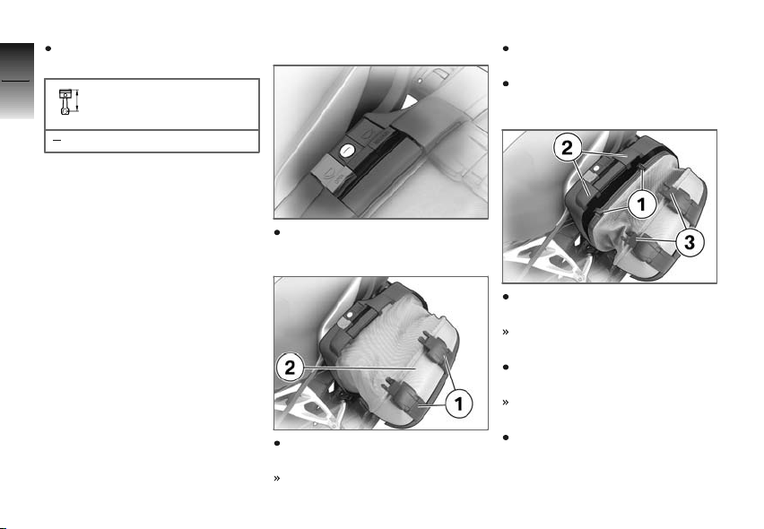
Comply with maximum payload
of luggage rack.
7
92
Payload of luggage carrier
Max 11 lbs (Max 5 kg)
OA
Case
Release levers
There is a release lever on the
left and right of each case lock.
The gray lever marked OPEN
z
Accessories
is used to open and close the
cases.
The black lever marked
RELEASE is used to remove and
attach the cases.
Opening case
Turn lock barrel in direction
OPEN.
Pull gray release lever (OPEN)
upward.
Lock straps 1 open.
Pull gray release lever (OPEN)
upward again.
Pull case lid 2 out of retainer.
Closing case
Press catches 1 of case lid into
the retainers 2.
The catches can be heard to
lock into place.
Press catches 3 of lock straps
into retainers 2.
The catches can be heard to
lock into place.
Make sure catches are secure.
Page 95
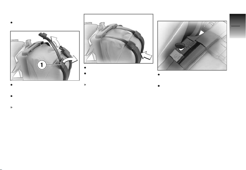
Adjusting case volume
Close case lid.
Turn lock strap buckles 1 of
lock straps outward.
Pull out the lock straps upwards.
The maximum volume has
been set.
Close the lock straps.
Press the lock straps against
the case body.
The case volume is adapted to
the contents.
Removing case
Turn lock barrel in direction
RELEASE.
Pull black release lever (RELEASE) upward.
7
93
z
Accessories
Page 96
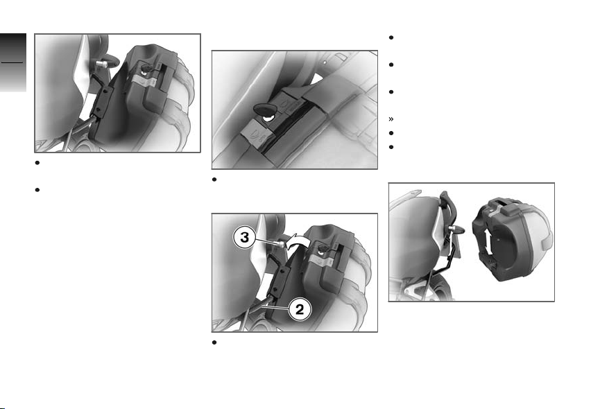
7
94
Pull the case out of the upper
mounting.
Lift the case out of the lower
mounting.
z
Accessories
Mounting case
Turn lock barrel in direction
RELEASE.
Hook case into lower mounting 2.
Pull black release lever (RELEASE) upward.
Press case into upper mounting 3.
Press black release lever (RELEASE) downward.
Case is locked into place.
Lock the case.
Check secure locking.
Secure hold
If a case wobbles or is difficult to
mount, it has to be adapted to
the gap between the upper and
lower mounting. To achieve this,
the height of the lower bracket
on the case can be changed.
Page 97
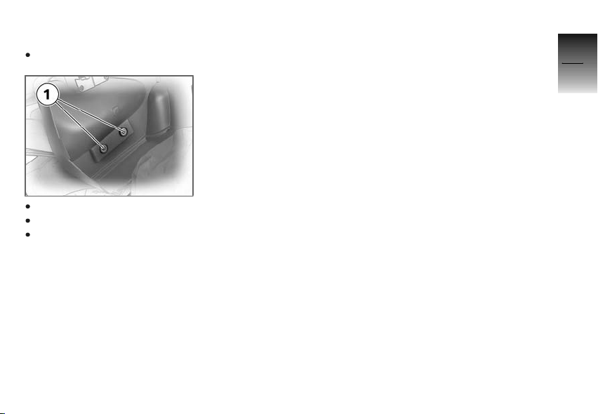
Adapting case
Open case.
7
95
Unfasten screws 1.
Adjust height of bracket.
Tighten screws 1.
z
Accessories
Page 98

7
96
z
Accessories
Page 99

Maintenance
General instructions .................. 98
Toolkit ............................... 98
Engine oil ............................ 99
General brake system .............. 101
Brake pads . . . ..................... 101
Brake fluid ......................... 103
Clutch ............................. 105
Tires ............................... 106
Rims ............................... 106
Wheels ............................ 107
Front wheel stand ................. 114
Rear-wheel stand .................. 115
Lamps ............................. 116
Jump-starting. ..................... 123
Battery ............................. 124
8
97
z
Maintenance
Page 100
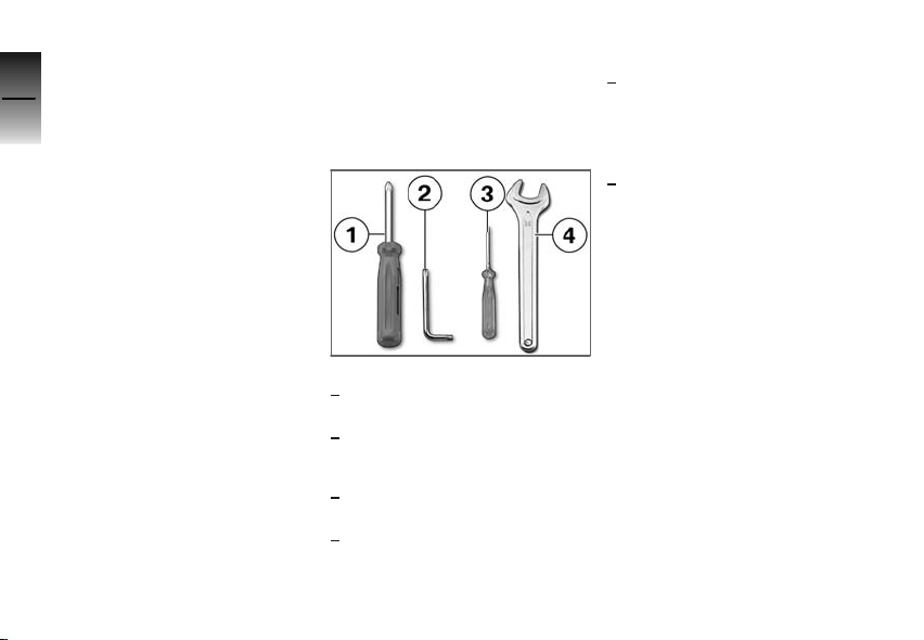
General instructions
8
The 'Maintenance' chapter describes work involving the check-
98
ing and replacement of wear
parts that can be performed with
a minimum of effort.
If special tightening torques are
to be taken into account for
assembly, these are listed. An
overview of all required tightening
torques is contained in the
chapter "Technical Data".
Information on additional mainte-
z
Maintenance
nance and repair work is provided in the Repair Manual for your
motorcycle on DVD/CD-ROM
(RepROM), which you can obtain from your authorized BMW
Motorrad retailer.
Special tools and a thorough
knowledge of motorcycles are
required to carry out some of the
work described here. If you are
in doubt, consult a certified work-
shop, preferably your authorized
BMW Motorrad retailer.
Toolkit
Standard toolkit
1 Reversible screwdriver
Removing and installing turn
indicator glasses
Disconnecting battery terminals
2 Torx wrench, T25
Removing and installing body
panels
Removing and installing battery
retaining strap
3 Small screwdriver
Removing and installing turn
indicator glasses
4 Open-ended wrench, 14
mm
Adjusting mirror arm
Onboard-toolkit service
set
Your BMW Motorrad retailer offers the onboard-toolkit service
set for additional work.
Information on conducting this
work is provided in the Repair
Manual on DVD/CD-ROM, which
is also available from your BMW
Motorrad retailer.
 Loading...