


L8542678
03/2012 rev 2
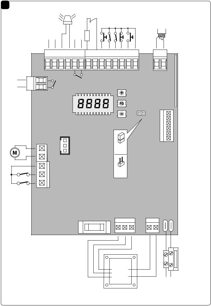
CP.B24ESA
CP.B1024ESA
|
|
|
|
|
|
|
|
|
|
|
|
|
|
|
|
|
|
|
|
|
|
|
|
|
|
|
|
|
|
|
|
|
|
|
|
|
|
|
|
|
|
|
|
|
|
|
|
|
|
|
|
|
|
|
|
|
|
|
|
|
|
|
|
|
|
|
|
|
|
|
|
|
|
|
|
|
|
|
|
|
|
|
|
|
|
|
|
|
|
|
|
|
|
|
|
|
|
|
|
|
|
|
|
|
|
|
|
|
|
|
|
|
|
|
|
|
|
|
|
|
|
|
|
|
|
|
|
|
|
|
|
|
|
|
|
|
|
|
|
|
|
|
|
|
|
|
|
|
|
|
|
|
|
|
|
|
|
|
|
|
|
|
|
|
|
|
|
|
|
|
|
|
|
|
|
|
|
|
|
|
|
|
|
|
|
|
|
|
|
|
|
|
|
|
|
|
|
|
|
|
|
|
|
|
|
|
|
|
|
|
|
|
|
|
|
|
|
|
|
|
|
|
|
|
|
|
|
|
|
|
|
|
|
|
|
|
|
|
|
|
|
|
|
|
|
|
|
|
|
|
|
|
|
|
|
|
|
|
|
|
|
|
|
|
|
|
|
|
|
|
|
|
|
|
|
|
|
|
|
|
|
|
|
|
|
|
|
|
|
|
|
|
|
|
|
|
|
|
|
|
|
|
|
|
|
|
|
|
|
|
|
|
|
|
|
|
|
|
|
|
|
|
|
|
|
|
|
|
|
|
|
|
|
|
|
|
|
|
|
|
|
|
CP.B24ESA |
|
|
|
|
CP.B1024ESA |
||||||||
|
|
|
|
|
|
|
|
|
|
|
|
|
|
|
|
|
|
|
|
|
|
|
|
|
|
|
|
|
|
|
|
|
|
|
|
|
|
|
|
|
|
|
|
|
|
|
|
|
|
|
UNIONE NAZIONALE COSTRUTTORI AUTOMATISMI PER CANCELLI, PORTE SERRANDE ED AFFINI
1 |
|
|
|
LAMP |
|
|
|
|
|
|
|
|
|
|
|
|
|
|
|
|
|
|
|
|
|
|
|
|
|
|
|
|
|
|
|
|
|
|
|
24Vdc |
|
|
|
|
|
|
|
|
|
|
|
|
|
|
24Vdc |
|
|
AUX1 |
|
|
|
|
|
|
|
|
|
|
|
|
|
|
500mA max |
|
|
|
8k2 |
DAS |
|
|
|
|
|
|
|
|
ANT |
||
|
- |
+ |
|
|
|
|
|
|
|
|
|
|
|
|
|||
|
-24V |
+24V |
BLINK |
BLINK |
AUX1 |
AUX1 |
BAR |
BAR |
PED |
PHO |
PHC |
STOP |
P.P. |
+COM |
|
SHIELD |
ANT |
|
AUX2 |
|
|
|
|
|
|
|
|
|
|
|
|
|
|
|
DIO |
AUX2 |
|
|
|
|
|
|
|
|
|
|
|
|
|
|
|
A |
|
|
|
|
|
|
|
|
|
|
|
|
|
|
|
|
|
||
AUX2 |
|
|
|
|
|
|
|
|
|
|
|
|
|
|
|
R |
|
|
|
|
|
|
|
|
|
|
|
|
|
|
|
|
|
||
|
|
|
|
|
|
|
|
|
|
|
|
|
|
|
|
|
|
|
|
|
|
|
|
|
|
|
|
|
|
|
|
|
DAS |
CHARGER |
|
|
|
|
|
|
|
|
|
|
|
|
|
|
|
|
|
|
|
|
|
|
|
ENCODER |
|
|
|
|
|
|
J1 DAS |
|
|
BATTERY |
|
||
|
|
|
|
|
|
|
|
|
|
Close |
|
|
|
|
|||
|
MOT |
|
|
|
|
|
|
DAS 8K2 |
|
|
|
||||||
|
|
|
|
|
|
|
|
|
|
|
|
|
|||||
|
|
COM |
|
|
|
|
|
|
|
|
|
|
|
|
|
|
|
|
|
|
|
|
|
|
|
|
|
|
|
J1 DAS |
|
|
|
|
|
|
|
|
|
|
|
|
|
|
|
|
|
Open |
|
|
|
|
|
|
|
SWO |
|
|
|
|
|
|
|
|
DAS N.C. |
|
|
|
|
||
|
|
|
|
|
|
|
|
|
|
|
|
|
|
|
|
|
|
|
|
SWC |
|
|
|
|
|
|
|
|
|
|
|
|
|
|
|
|
|
|
|
|
|
|
|
|
|
|
|
0V |
MOT |
AUX |
L1 |
N1 |
|
|
|
|
|
|
|
|
|
F1 |
|
|
|
|
|
|
|
|
|
|
|
|
|
|
|
|
|
|
|
|
|
|
|
|
|
|
F2 |
|
|
|
|
|
|
|
|
|
|
|
0V |
|
L1 |
|
|
|
|
|
|
|
|
|
|
|
|
|
|
|
MOT |
|
|
|
|
|
|
|
|
|
|
|
|
|
|
|
|
|
AUX |
N1 |
|
|
|
|
|
|
|
|
|
|
|
|
|
|
|
|
|
|
|
|
|
|
N L |
|
CP.B24 ESA |
CP.B1024 ESA |
CP.B24 ESA-A |
CP.B1024 ESA-A |
|
|
|
|
|
F1 |
|
|
T2A |
|
|
|
|
|
|
F2 |
T1A |
T2A |
T2A |
T4A |
|
|
|
|
|
2

2 |
SCA |
|
|
|
|
|
|
|
II°CH RADIO |
|
|
|
|
SERVICE/ZONE LIGHT |
|
|
|
|
|
|
|
|
||||||
|
|
|
|
|
|
|
|
|
|
|
|
|
|
|
|
|
AUX1:2 |
|||||||||||
|
|
|
|
|
|
|
|
|
|
|
|
|
|
|
|
|
|
|
|
|
|
Service Light |
||||||
|
|
|
|
|
|
AUX1:0 |
|
|
|
|
|
AUX1:1 |
|
|
|
|
|
|
Zone Light |
AUX1:3 |
||||||||
|
24Vac |
|
|
|
|
|
|
|
|
|
|
|
|
|
|
|
|
|
|
|
||||||||
|
|
|
|
|
|
|
|
|
|
|
|
|
|
|
|
|
|
|
|
|
|
|
|
|
|
|
||
|
500mA max |
SCA 24Vac |
|
|
|
|
|
|
|
|
|
|
|
|
|
|
|
|
|
|
|
|
|
|||||
|
|
|
|
|
|
|
|
|
|
|
|
|
|
|
|
|
|
L |
|
N |
|
|
|
|
||||
|
|
|
|
|
3W max |
|
|
|
|
|
|
|
|
|
|
|
|
|
|
|
|
|
|
|
||||
|
|
|
|
|
|
|
|
|
|
|
|
|
|
|
|
|
|
|
|
|
|
|
|
|
|
|||
|
|
|
|
|
|
|
|
|
|
|
|
|
|
|
|
|
|
|
|
|
|
|
|
|
Service/Zone |
|
|
|
|
|
|
|
|
|
|
|
|
|
|
|
|
|
|
|
|
|
|
|
|
|
|
|
|
Light |
|
|
|
|
|
|
|
|
|
|
|
|
|
|
|
|
|
|
|
|
|
|
Relè 24Vac |
|
|
|
|
230Vac |
|
|
||
|
-24V |
+24V |
BLINK |
BLINK |
AUX1 |
AUX1 |
BAR |
BAR |
-24V |
+24V |
BLINK |
BLINK |
AUX1 |
AUX1 |
BAR |
BAR |
|
|
|
|
|
|
|
|
|
|
|
|
|
|
|
|
|
|
|
|
|
|
|
|
|
|
|
|
-24V |
+24V |
BLINK |
BLINK |
AUX1 |
AUX1 |
BAR |
|
BAR |
CLOSE |
OPEN |
PHOT |
STOP |
3 |
|
|
|
|
|
|
|
|
|
|
|
|
|
|
|
|
|
|
|
|
|
|
|
|
|
|
|
|
|
SCA |
|
AUX2:0 |
|
|
|
|
II°CH RADIO |
|
AUX2:1 |
|
SERVICE/ZONE LIGHT |
|
|
|
|
|
|
|
|
||||||||
|
|
|
|
24Vdc |
|
|
|
|
|
|
|
|
|
|
|
|
Service Light |
AUX2:2 |
||||||||||
|
|
|
|
|
|
1A max |
|
|
|
|
|
|
|
|
|
|
|
|
|
|
|
|
|
|
AUX2:3 |
|||
|
|
|
|
|
|
|
|
|
|
|
|
|
|
|
|
|
|
|
|
|
|
Zone Light |
|
|||||
|
|
|
|
|
|
|
|
|
|
|
|
|
|
|
|
|
|
|
|
|
|
|
L |
|
N |
|
|
|
|
|
|
|
|
|
|
|
|
|
|
|
|
|
|
|
|
|
|
|
|
|
|
|
|
Service/Zone |
|
||
|
|
|
|
|
|
|
|
|
|
|
|
|
24V- |
+24V |
BLINK |
|
|
|
Relè 24Vdc |
|
|
|
|
|
Light |
|
|
|
|
|
|
|
|
|
24V- |
+24V |
BLINK |
|
|
|
|
|
|
|
|
|
|
|
|
230Vac |
|
||||||
|
|
|
|
|
|
|
|
|
|
|
|
|
|
|
|
|
|
|
|
|
||||||||
|
|
|
|
|
|
|
|
|
|
|
|
|
|
|
|
|
|
|
|
|
|
|
|
|
|
|
||
|
|
|
|
|
|
|
|
|
|
|
|
|
|
|
|
|
|
|
|
-24V |
|
+24V |
BLINK |
BLINK |
AUX1 |
AUX1 |
|
|
|
|
|
AUX2 |
|
|
|
|
|
|
|
AUX2 |
|
|
|
|
|
|
|
|
|
|
|
|
|
|
|
|
|
|
|
|
|
|
|
|
|
|
|
|
|
|
|
|
|
|
|
|
|
|
|
|
|
|
|
|
|
|
|
|
|
AUX2 |
|
|
|
|
|
|
|
AUX2 |
|
|
|
|
|
|
|
|
|
|
|
|
|
|
|
|
|
|
|
|
|
|
|
|
|
|
|
|
|
|
|
|
|
|
AUX2 |
|
|
|
|
|
|
|
|
|
|
|
|
|
|
|
|
|
|
|
|
|
|
|
|
|
|
|
|
|
|
|
|
|
|
|
|
|
|
|
|
|
SCA 24Vdc |
|
|
|
|
|
|
|
|
|
|
|
|
|
|
AUX2 |
|
|
|
|
|
|
|
|
|
|
||
|
3W max |
|
|
|
|
|
|
|
|
|
|
|
|
|
|
|
|
|
|
|
|
|
|
|
|
|||
|
|
|
|
|
|
|
|
|
|
|
|
|
|
|
|
|
|
|
|
|
|
|
|
|
|
|||
4
MINV:ON
OPEN
MINV:OFF
OPEN
3

EC Declaration of Conformity
Pursuant to Directives 2004/108/CE(EMC); 2006/95/CE(LVD)
Manufacturer:
Automatismi Benincà SpA.
Address:
Via Capitello, 45 - 36066 Sandrigo (VI) – Italy
It is hereby stated that the item:
Control unit for 1 24VDC for sliding gates:CP.B24ESA /CP.B1024ESA
it is compliant with provisions of the following other EC Directives:
• DIRECTIVE 2004/108/EC OF THE EUROPEAN PARLIAMENT AND OF THE COUNCIL of 15 December 2004, on the harmonisation of the laws of Member States relating to electromagnetic compatibility and which cancels Directive 89/336/
EEC, according to the following harmonised regulations:
EN 61000-6-2:2005, EN 61000-6-3:2007.
• DIRECTIVE 2006/95/EC OF THE EUROPEAN PARLIAMENT AND OF THE COUNCIL of 12 December 2006, on the harmonisation of the laws of Member States relating to electrical equipment designed for use with certain voltage limits,
according to the following harmonised regulations:
EN 60335-1:2002 + A1:2004 + A11:2004 + A12:2006 + A2:2006 + A13:2008; EN 60335-2-103:2003.
if applicable:
• DIRECTIVE 1999/5/EC OF THE EUROPEAN PARLIAMENT AND OF THE COUNCIL of 9 March 1999 on radio equipment and telecommunications terminal equipment and the mutual recognition of their conformity, according to the following harmonised standards: ETSI EN 301 489-3 V1.4.1 (2002) + ETSI EN 301 489-1 V1.4.1 (2002) + ETSI EN 300 220-3
V1.1.1 (2000) + EN 60950-1 (2001)
Benincà Luigi, Legal Officer.
Sandrigo, 05/07/2011.
WARNINGS
This manual has been especially written to be use by qualified fitters.
None of the information provide in this manual can be considered as being of interest for the end users.
Preserve this manual for future needs.
The technician has to furnish all the information related to the step by step function, the manual and the emergency function of the operator, and to deliver the manual to the final user.
Foresee on the supply net an onnipolar switch or selector with distance of the contacts equal or superior to 3 mms.
Verify that of the electrical system there is an awry differential interrupter and overcurrent protection.
Some typologies of installation require the connection of the shutter to be link at a conductive mass of the ground according to the regulations in force.
The electrical installation and the operating logic must comply with the regulations in force.
The leads fed with different voltages must be physically separate, or they must be suitably insulated with additional insulation of at least 1 mm.
The leads must be secured with an additional fixture near the terminals.
During installation, maintenance and repair, interrupt the power supply before opening the lid to access the electrical parts
Check all the connections again before switching on the power.
The unused N.C. inputs must be bridged.
The descriptions and the present illustrations in this manual are not binding. Leaving the essential characteristics of the product unchanged, the manufacturer reserves himself the right to bring any change of technical, constructive or commercial character without undertaking himself to update the present publication.
12
 Loading...