


L8542910
04/2012 rev. 2
BRAINY
UNIONE NAZIONALE COSTRUTTORI AUTOMATISMI PER CANCELLI, PORTE SERRANDE ED AFFINI

Fig. 1 BRAINY |
|
|
|
|
|
|
|
|
|
|
|
|
|
|||
F2 |
|
|
|
|
|
|
|
|
|
RADIO |
|
3536 |
ANT |
|
|
|
|
|
|
|
|
|
|
|
|
|
|
|
ANT |
|
|||
|
|
|
|
|
|
|
|
|
|
|
|
|
SHIELD |
|
||
|
|
|
|
|
|
|
|
|
|
|
|
|
|
|
|
|
|
|
|
|
|
|
|
|
37 38 |
|
|
|
|
34 |
|
STOP |
|
|
|
|
|
|
|
|
|
|
|
|
|
|
|
|||
|
|
|
|
|
|
|
|
|
|
|
|
|
33 |
|
PHOT (Close) |
|
|
|
|
|
|
|
|
|
|
|
|
|
|
32 |
|
PHOT |
|
|
|
|
|
|
|
|
|
AUX2 |
|
|
|
|
31 |
|
CLOSE |
|
|
|
|
|
|
|
|
|
|
DAS |
U11 |
|
30 |
|
OPEN |
||
|
|
|
|
|
|
|
|
|
|
|
|
|||||
|
|
|
|
|
|
|
|
|
|
|
|
29 |
|
PED. |
||
|
|
|
|
|
|
|
|
|
|
|
|
|
|
|||
|
|
|
|
|
|
|
|
|
|
|
|
|
28 |
|
P.P. |
|
|
|
|
|
|
|
|
|
|
|
|
|
|
27 |
|
COM |
|
|
|
|
|
|
|
|
|
|
|
|
|
|
26 |
|
COM |
|
|
|
|
|
|
|
|
|
14 15 16 17 18 19 |
J2 DAS |
|
|
25 |
|
SWC-M2 (Close) |
||
|
|
|
|
|
|
|
|
Close |
|
|
|
|||||
|
|
|
|
|
|
|
|
|
|
24 |
|
|||||
|
|
|
|
|
|
|
|
DAS 8K2 |
|
|
|
SWO-M2 (Open) |
||||
|
|
|
|
|
|
|
|
|
|
|
|
|
|
|||
|
|
|
|
|
|
|
|
|
|
|
|
|
23 |
|
SWC-M1 (Close) |
|
|
|
|
|
|
|
|
|
|
|
|
|
|
22 |
|
SWO-M1 (Open) |
|
|
|
|
|
|
|
|
|
24Vac |
Lock AUX1 |
J2 DAS |
|
|
21 |
8k2 |
|
|
|
|
|
|
|
|
|
|
Open |
|
|
20 |
DAS |
|
|||
|
|
|
|
|
|
|
|
500mA max |
DAS N.C. |
|
|
|
||||
|
|
|
|
|
|
|
|
12Vac |
|
|
|
|
|
|
|
|
|
|
|
|
|
|
|
|
|
10W |
|
|
|
|
Encoder M1 |
Encoder M2 |
|
|
|
|
|
|
|
|
|
|
|
|
|
|
|
|||
F1 |
|
|
|
|
|
|
|
|
|
|
Encoder M1 |
Encoder |
|
|
|
|
|
|
|
|
|
|
|
|
|
|
|
|
|
|
|||
L |
N |
4 |
5 |
6 |
7 |
8 |
9 |
10 11 12 13 |
|
|
|
|
|
+ |
s - |
+ s - |
|
|
|
|
|
|
|
|
|||||||||
GND L |
|
|
COM |
|
|
COM |
|
|
|
|
|
M1 |
|
|
|
|
|
|
|
|
|
|
|
|
|
|
|
|
|
M1 |
M2 |
||
N |
|
M1 |
|
|
M2 |
|
TLS |
|
|
|
|
|
|
|||
115/230Vac |
|
|
|
|
|
|
|
|
|
|||||||
|
|
|
|
|
|
|
|
|
|
|
|
|
|
|||
50/60Hz |
|
|
|
|
|
|
|
|
|
|
|
|
|
3+3 x 0.5mm2 |
||
|
|
|
C |
|
|
C |
|
|
|
|
|
|
|
|
||
|
|
|
|
|
|
LAMP |
|
|
|
|
|
|
max 10m |
|||
|
|
|
|
|
|
|
|
|
|
|
|
|
|
|
|
|
|
|
|
|
|
|
|
|
230Vac |
|
|
|
|
|
|
|
|
SCA |
|
|
|
|
|
PHOTO-TEST |
|
|
|
|
|
|
|
|
||
|
|
|
|
|
|
|
|
|
OPEN/CLOSE |
|
|
|
|
CLOSE |
|
|
14 15 16 17 18 19 |
|
|
|
14 15 16 17 18 19 |
27 28 29 31 31 32 33 |
14 15 16 17 18 19 |
27 28 29 31 31 32 33 |
|||||||||
|
|
|
|
|
|
|||||||||||
24Vac |
SCA 24Vac |
|
|
|
|
24Vac |
|
NCNOCOM 24Vac |
|
24Vac |
|
|
NCNOCOM 24Vac |
|||
|
3W max |
|
|
|
|
|
|
|
|
|
|
|
|
|
|
|
1A max |
|
|
|
|
|
|
|
|
|
|
|
|
|
|
|
|
|
|
|
|
|
|
|
|
TX1 |
|
RX1 |
|
TX2 |
|
|
RX2 |
|
 Code ____
2
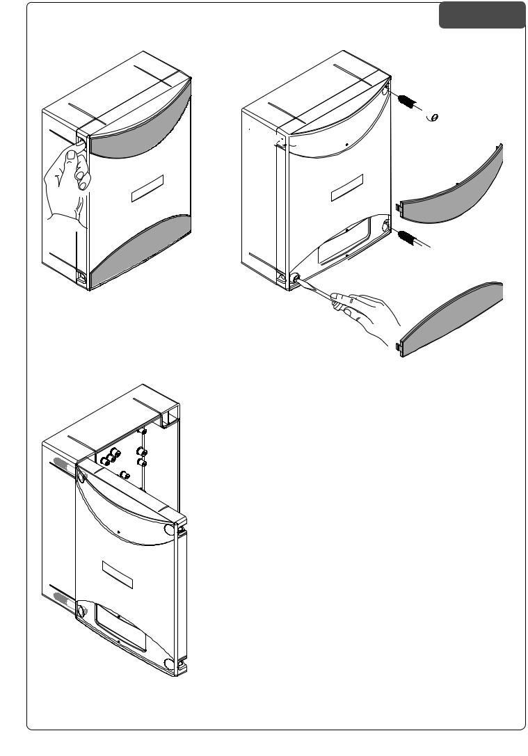
LB-BOX


1SFNFSF MF BMFUUF TVJ mBODIJ QFS THBO |
1SFTTFS MFT EFVY BJMFUUFT MBUÏSBMFT QPVS |
DJBSF MF EVF NBTDIFSF DPQSJWJUJ |
EÏDSPDIFS MFT EFVY DBDIF WJT |
3JNVPWFSF MF EVF WJUJ TVM MBUP EJ BQFSUV |
&OMFWFS MFT EFVY WJT TVS MF DÙUÏ |
SB EFTJEFSBUP |
E PVWFSUVSF EÏTJSÏ |
"MMFOUBSF MF EVF WJUJ DPO GVO[JPOF EJ |
%FTTFSSFS MFT EFVY WJT GBJTBOU GPODUJPO |
DFSOJFSB TFO[B SJNVPWFSMF JO NPEP EB |
EF DIBSOJÒSF TBOT MFT FOMFWFS EF NB |
DPOTFOUJSF M BQFSUVSB EFM DPQFSDIJP |
OJÒSF Ë QFSNFUUSF M PVWFSUVSF EV DPV |
|
WFSDMF |
1SFTT UIF UBCT PO UIF TJEFT UP SFMFBTF |
1SFTJPOBS MBT BMFUBT FO MPT MBEPT QBSB |
UIF UXP NBTLT UIBU DPWFS UIF TDSFXT |
EFTFOHBODIBS MBT EPT UBQBT DVCSFUPS |
3FNPWF UIF UXP TDSFXT PO UIF EFTJSFE |
OJMMPT |
PQFOJOH TJEF |
&YUSBFS MPT EPT UPSOJMMPT EFM MBEP EF |
4MBDLFO UIF UXP TDSFXT UIBU BDU BT B |
BQFSUVSB EFTFBEP |
IJOHF XJUIPVU SFNPWJOH UIFN TP BT UP |
"nPKBS MPT EPT UPSOJMMPT DPO GVODJØO EF |
BMMPX PQFOJOH PG UIF DPWFS |
CJTBHSB TJO FYUSBFSMPT B mO EF QPEFS |
|
BCSJS MB UBQB |
"VG EJF TFJUMJDIFO -BTDIFO ESàDLFO |
/BDJTOįİ CPD[OF LMBQLJ X DFMV PEIB |
TP EBTT EJF CFJEFO 4DISBVCFOCMFOEFO |
D[FOJB EXØDI NBTFL OBLSZ XBKįDZDI |
CFGSFJU XFSEFO |
ŔSVCZ |
%JF CFJEFO 4DISBVCFO BO EFS HF |
8ZDJįHOįİ EXJF ŔSVCZ QP XZCSBOFK EP |
XàOTDIUFO ½GGOVOHTTFJUF BVTCBVFO |
PUXJFSBOJB TUSPOJF |
;VMFU[U EJF CFJEFO BMT 4DIBSOJFS EJF |
1PMV[PXBİ EXJF ŔSVCZ CMPLVKįDF CF[ |
OFOEFO 4DISBVCFO MPDLFSO BCFS OJDIU |
XZDJįHBOJB JDI X TQPTØC VNPŤMJ |
BVTCBVFO EBNJU EFS %FDLFM HFÚGGOFU |
XJBKįDZ PUXBSDJF OBLSZXLJ |
XFSEFO LBOO |
|
3

EC Declaration of conformity
Declaration pursuant to Directives 2004/108/EC(EMC); 2006/95/EC(LVD)
Manufacturer:
Automatismi Benincà SpA
Address:
Via Capitello, 45 - 36066 Sandrigo (VI) - Italy
Declares that the product:
Command central for 1/2 230 Vac motor, for single or sliding doors: BRAINY is compliant with the conditions of the following EC Directives:
• DIRECTIVE 2004/108/EC OF THE EUROPEAN PARLIAMENT AND COUNCIL of December 15 2004 regarding the approximation of the legislations of the member States relative to electromagnetic compatibility and that repeals directive 89/336/CEE, according to the following concurred norms:
EN 61000-6-2:2005, EN 61000-6-3:2007.
• DIRECTIVE 2006/95/EC OF THE EUROPEAN PARLIAMENT AND THE COUNCIL of December 12 2006 concerning the approximation of the legislations of the member States relative to electrical material destined to be used within certain voltage limits, according to the following concurred regulations:
EN 60335-1:2002 + A1:2004 + A11:2004 + A12:2006 + A2:2006 + A13:2008; EN 60335-2-103:2003. if applicable :
• DIRECTIVE 1999/5/EC OFTHE EUROPEAN PARLIAMENTAND THE COUNCIL of March 9 1999 regarding radio devices and terminal and telecommunications devices and the reciprocal recognisances of their conformity, according to the following concurred regulations: ETSI EN 301 489-3 V1.4.1 (2002) + ETSI EN 301 489-1 V1.4.1 (2002) + ETSI EN 300 220-3 V1.1.1 (2000) + EN 60950-1 (2001)
Benincà Luigi, Legal manager.
Sandrigo, 02/11/2010.
WARNINGS
This manual has been especially written to be use by qualified fitters.
None of the information provide in this manual can be considered as being of interest for the end users.
Preserve this manual for future needs.
The technician has to furnish all the information related to the step by step function, the manual and the emergency function of the operator, and to deliver the manual to the final user.
•Foresee on the supply net an onnipolar switch or selector with distance of the contacts equal or superior to 3 mms.
Verify that of the electrical system there is an awry differential interrupter and overcurrent protection.
Some typologies of installation require the connection of the shutter to be link at a conductive mass of the ground according to the regulations in force.
The electrical installation and the operating logic must comply with the regulations in force.
The leads fed with different voltages must be physically separate, or they must be suitably insulated with additional insulation of at least 1 mm.
The leads must be secured with an additional fixture near the terminals.
During installation, maintenance and repair, interrupt the power supply before opening the lid to access the electrical parts
Check all the connections again before switching on the power.
The unused N.C. inputs must be bridged.
The descriptions and the present illustrations in this manual are not binding. Leaving the essential characteristics of the product unchanged, the manufacturer reserves himself the right to bring any change of technical, constructive or commercial character without undertaking himself to update the present publication.
12
 Loading...