

Aprilia ETV MILLE CAPONORD User Manual 2003
ETV Caponordmille
use maintenance+ book
aprilia part# 8104310
© 2001 DSULOLDVSD- Noale (VE)
★
6$)(7<:$51,1*6
7(&+1,&$/,1)250$7,21
First edition: february 2001
Reprint: may 2003
Produced and printed by:
editing division
Soave (VERONA) - Italy
Tel. +39 - 045 76 11 911
Fax +39 - 045 76 12 241
E-mail: customer@stp.it
www.stp.it
On behalf of:
DSULOLDVSD
via G. Galilei, 1 - 30033 Noale (VE) - Italy
Tel. +39 - 041 58 29 111
Fax +39 - 041 44 10 54
www.aprilia.com
The following precautionary warnings are
used throughout this manual in order to
convey the following messages:
6DIHW\ZDUQLQJ:KHQ\RXILQGWKLV
V\PERORQ WKHYHKLFOH RULQWKH
PDQXDOEHFDUHIXOWRWKHSRWHQWLDO ULVN
RISHUVRQDOLQMXU\1RQFRPSOLDQFHZLWK
WKHLQGLFDWLRQV JLYHQ LQ WKHPHVVDJHV
SUHFHGHG E\WKLV V\PERO PD\ UHVXOWLQ
JUDYHULVNV IRU\RXUDQGRWKHUSHRSOH¶V
VDIHW\DQGIRUWKHYHKLFOH
:$51,1*
,QGLFDWHVD SRWHQWLDOKD]DUGZKLFKPD\
UHVXOWLQVHULRXVLQMXU\RUHYHQGHDWK
&$87,21
,QGLFDWHVD SRWHQWLDOKD]DUGZKLFKPD\
UHVXOWLQPLQRUSHUVRQDOLQMXU\RUGDP
DJHWRWKHYHKLFOH
127( The word “NOTE” in this manual
precedes important information or instructions.
The operations preceded by this
symbol must be repeated also on
the opposite side of the vehicle.
If not expressly indicated otherwise, for the
reassembly of the units repeat the disassembly operations in reverse order.
The terms “right” and “left” are referred to
the rider seated on the vehicle in the normal riding position.
:$51,1*6 35(&$87,216
*(1(5$/ $'9,&(
Before starting the engine, carefully read
this manual and in particular the section
“SAFE DRIVE”.
Your and other people’s safety depends
not only on your quickness of reflexes and
on your agility, but also on what you know
about the vehicle, on its efficiency and on
your knowledge of the basic information for
“SAFE DRIVE”. Therefore, get a thorough
knowledge of the vehicle, in such a way as
to be able to drive in the traffic safely.
127( Keep a stock of one bulb per type
with the vehicle (see technical data).
XVHDQGPDLQWHQDQFH
2
(79PLOOH&DSRQRUG
NOTE This manual must be considered
as an integral part of the vehicle and must
always accompany it, even in case of resale.
aprilia has carried out this manual with the
maximum attention, in order to supply the
user with correct and updated information.
However, since aprilia constantly improves the design of its products, there
may be slight discrepancies between the
characteristics of your vehicle and those
described in this manual. For any clarification concerning the information contained
in this manual, do not hesitate to contact
your aprilia Official Dealer.
For control and repair operations not expressly described in this publication, for the
purchase of aprilia genuine spare parts,
accessories and other products, as well as
for specific advice, contact exclusively
aprilia Official Dealers and Service Centers, which guarantee prompt and accurate
assistance.
Thank you for choosing aprilia. We wish
you a nice ride.
All rights as to electronic storage, reproduction and total or partial adaptation, with
any means, are reserved for all Countries.
NOTE In some countries the antipollu-
tion and noise regulations in force require
periodical inspections.
The user of the vehicle in these countries
must:
– contact an aprilia Official Dealer to have
the non-homologated components re-
placed with others homologated for use
in the country in question;
– carry out the required periodical inspec-
tions.
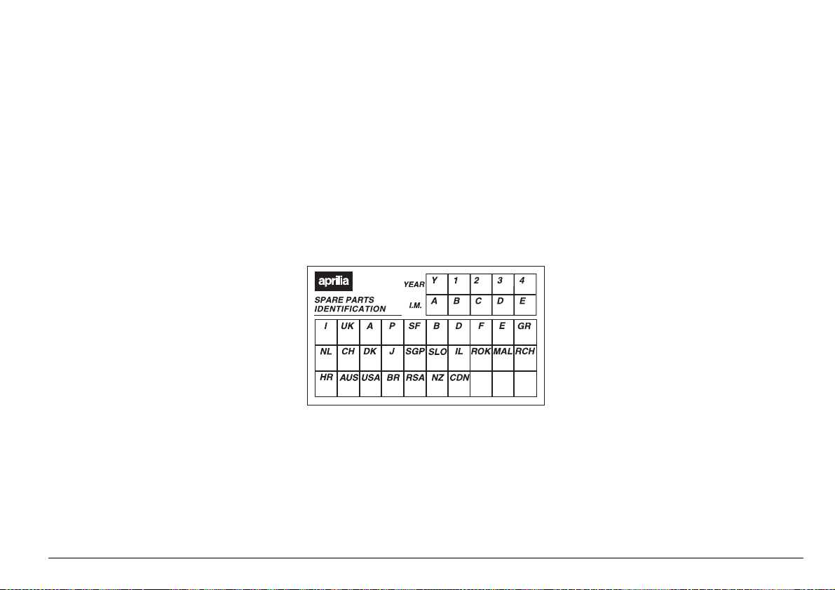
NOTE Soon after purchasing the vehi-
cle, write down the identification data indicated on the SPARE PARTS IDENTIFICATION LABEL in the table here below. This
label is positioned on the frame, under the
saddle; to read it, it is necessary to remove
the saddle, see p. 78 (REMOVING THE
RIDER SADDLE).
These data indicate:
– YEAR = year of manufacture (Y, 1, 2, ...);
– I.M. = modification code (A, B, C, ...);
– COUNTRY CODES = homologation coun-
try (I, UK, A, ...).
and are to be supplied to the aprilia Official
Dealer as reference data for the purchase
of spare parts or specific accessories of
the model you have acquired.
In this manual the various versions are indicated by the following symbols:
automatic light switching version
e
(Automatic Switch-on Device)
optional
m
catalytic version
o
VERSION:
I
U
a
p
F
B
d
f
E
G
O
Y
D
J
Italy
United Kingdom
Austria
Portugal
Finland
Belgium
Germany
France
Spain
Greece
Holland
Switzerland
Denmark
Japan
Singapore
S
Slovenia
s
Israel
i
South Korea
¬
Malaysia
M
Chile
c
Croatia
H
Australia
A
United States of
u
America
Brazil
Ä
South Africa
R
New Zealand
n
Canada
C
use and maintenance ETV mille Caponord
3

4!",%/&#/.4%.43
SAFE DRIVE ............................................................. 5
BASIC SAFETY RULES ...................................... 6
CLOTHING .......................................................... 9
ACCESSORIES ................................................. 10
LOAD ................................................................. 10
ARRANGEMENT OF THE MAIN ELEMENTS ....... 12
ARRANGEMENT OF THE
INSTRUMENTS/CONTROLS .................................. 14
INSTRUMENTS AND INDICATORS ....................... 15
INSTRUMENTS AND INDICATORS TABLE ..... 16
SETTING BUTTONS ......................................... 20
MAIN INDEPENDENT CONTROLS ........................ 22
CONTROLS ON THE LEFT PART OF THE
HANDLEBAR ..................................................... 22
CONTROLS ON THE RIGHT PART OF THE
HANDLEBAR ..................................................... 23
IGNITION SWITCH ............................................ 24
STEERING LOCK .............................................. 25
PARKING LIGHTS ............................................. 25
AUXILIARY EQUIPMENT ....................................... 26
UNLOCKING/LOCKING THE
PASSENGER SEAT .......................................... 26
UNLOCKING/LOCKING THE GLOVE/TOOL KIT
COMPARTMENT COVER ................................. 26
GLOVE/TOOL KIT COMPARTMENT ................ 27
SPECIAL TOOLS
OUTLET ............................................................. 28
ACCESSORIES ................................................. 28
MAIN COMPONENTS ............................................. 29
FUEL .................................................................. 29
BRAKE FLUID - recommendations .................... 30
DISC BRAKES ................................................... 31
FRONT BRAKE ................................................. 32
REAR BRAKE .................................................... 34
CLUTCH FLUID - recommendations ................. 35
CLUTCH ............................................................ 36
COOLANT .......................................................... 38
TYRES ............................................................... 40
ENGINE OIL ...................................................... 41
ADJUSTING THE FRONT BRAKE CONTROL
LEVER AND THE CLUTCH CONTROL LEVER 42
use and maintenance ETV mille Caponord
4
m
........................................ 28
ADJUSTING THE REAR BRAKE CONTROL
LEVER CLEARANCE ....................................... 42
AUTOMATIC LIGHT SWITCHING
VERSION
CATALYTIC SILENCER
EXHAUST SILENCER/EXHAUST TERMINAL . 43
INSTRUCTIONS FOR USE .................................... 44
GETTING ON AND OFF THE VEHICLE .......... 44
PRELIMINARY CHECKING OPERATIONS ..... 46
PRELIMINARY CHECKING OPERATIONS ..... 47
STARTING ........................................................ 48
DEPARTURE AND DRIVE ............................... 51
RUNNING-IN ..................................................... 54
STOPPING ........................................................ 55
PARKING .......................................................... 55
POSITIONING THE VEHICLE ON THE STAND 56
SUGGESTIONS TO PREVENT THEFT ........... 58
MAINTENANCE ..................................................... 58
REGULAR SERVICE INTERVALS CHART ...... 60
IDENTIFICATION DATA ................................... 62
JOINTS WITH CLICK CLAMPS AND WITH
SCREW CLAMPS ............................................. 62
CHECKING THE ENGINE OIL LEVEL AND
TOPPING UP .................................................... 63
CHANGING THE ENGINE OIL AND THE OIL
FILTER .............................................................. 64
AIR CLEANER .................................................. 66
FRONT WHEEL ................................................ 68
FRONT BRAKE CALIPERS .............................. 70
REAR WHEEL .................................................. 71
POSITIONING THE VEHICLE ON THE FRONT
SUPPORT STAND
REMOVING THE OIL SUMP GUARD .............. 75
REMOVE THE LEFT FAIRING ......................... 75
REMOVAL OF THE FUEL TANK ...................... 76
REMOVING THE FUSE BOX COVER ............. 78
REMOVING THE RIDER SADDLE ................... 78
REAR-VIEW MIRRORS .................................... 79
DRIVE CHAIN ................................................... 80
CHECKING THE STEERING ............................ 82
CHECKING THE REAR FORK
FULCRUM AXIS ............................................... 82
e
.................................................... 43
o
............................. 43
m
..................................... 74
INSPECTING THE FRONT AND REAR
SUSPENSIONS ................................................ 83
FRONT SUSPENSION ..................................... 83
REAR SUSPENSION ........................................ 84
CHECKING THE BRAKE PAD WEAR .............. 86
IDLING ADJUSTMENT ..................................... 87
ADJUSTING THE ACCELERATOR
CONTROL ......................................................... 87
CHECKING THE STAND .................................. 88
SPARK PLUGS ................................................. 90
BATTERY .......................................................... 92
CHECKING AND CLEANING THE
TERMINALS ...................................................... 92
REMOVING THE BATTERY ............................. 93
CHECKING THE ELECTROLYTE LEVEL ........ 93
RECHARGING THE BATTERY ........................ 94
INSTALLING THE BATTERY ............................ 94
LONG INACTIVITY OF THE BATTERY ............ 95
CHECKING THE SWITCHES ........................... 95
AIR TEMPERATURE SENSOR CONTROL ..... 95
CHANGING THE FUSES .................................. 96
HORIZONTAL ADJUSTMENT OF THE
HEADLIGHT BEAM ........................................... 98
ADJUSTING THE VERTICAL HEADLIGHT
BEAM ................................................................ 98
DASHBOARD LIGHTING .................................. 99
BULBS ............................................................... 99
CHANGING THE HEADLIGHT BULBS .......... 100
CHANGING THE FRONT DIRECTION
INDICATOR BULBS ........................................ 101
CHANGING THE REAR DIRECTION
INDICATOR BULBS ........................................ 102
CHANGING THE REAR LIGHT BULB ............ 102
CHANGING THE NUMBER PLATE
BULB ............................................................... 103
TRANSPORT ........................................................ 104
CLEANING ........................................................... 104
LONG PERIODS OF INACTIVITY .................. 106
TECHNICAL DATA .............................................. 107
LUBRICANT CHART ....................................... 110
Importers .................................................. 112-113
WIRING DIAGRAM - ETV mille Caponord ...... 114

safe drive
"!3)#3!&%4925,%3
To drive the vehicle it is necessary to be in
possession of all the requirements prescribed by law (driving licence, minimum
age, psychophysical ability, insurance,
state taxes, vehicle registration, number
plate, etc.).
Gradually get to know the vehicle by driving it first in areas with low traffic and/or private areas.
use and maintenance ETV mille Caponord
6
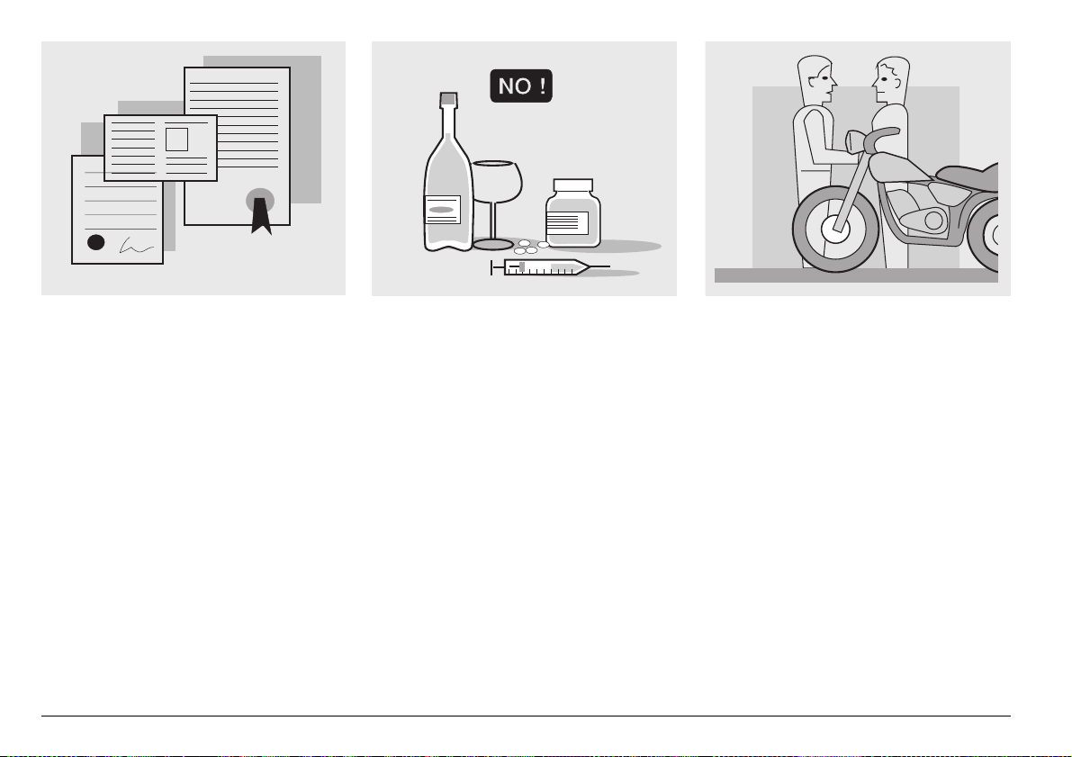
The use of medicins, alcohol and drugs or
psychotropic substances notably increases
the risk of accidents.
Be sure that you are in good psychophysical conditions and fit for driving and pay
particular attention to physical weariness
and drowsiness.
Most road accidents are caused by the
driver’s lack of experience.
NEVER lend the vehicle to beginners and,
in any case, make sure that the driver has
all the requirements for driving.
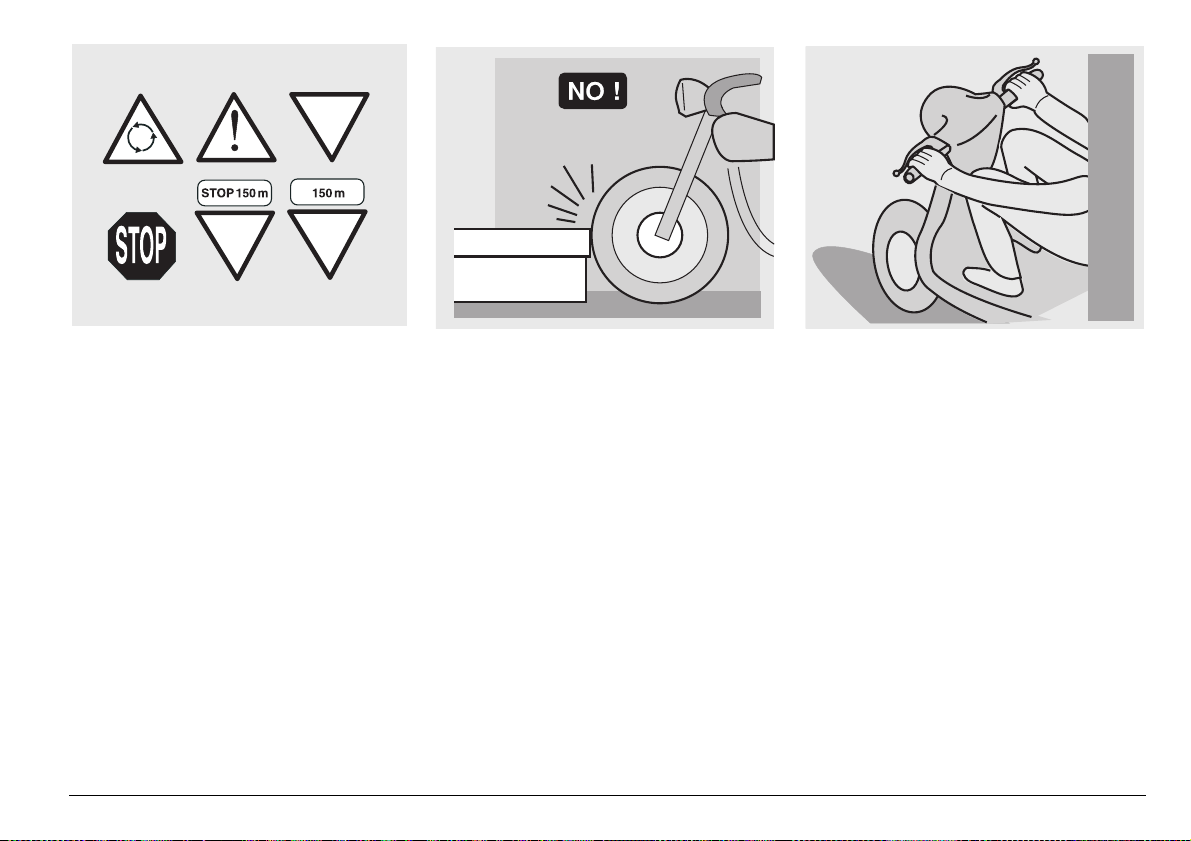
Rigorously observe all road signs and national and local road regulations.
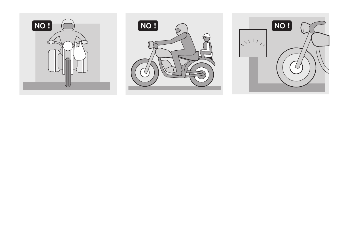
Avoid abrupt movements that can be dangerous for yourself and other people (for
example: rearing up on the back wheel,
speeding, etc.), and give due consideration
to the road surface, visibility and other driving conditions.
Avoid obstacles that could damage the vehicle or make you lose control.
Avoid riding in the slipstream created by
preceding vehicles in order to increase
your speed.
Always drive with both hands on the handlebars and both feet on the footrests (or
on the rider’s footboards), in the correct
driving posture.
Avoid standing up or stretching your limbs
while driving.
use and maintenance ETV mille Caponord
7
OIL
COOLER
The driver should pay attention and avoid
distractions caused by people, things and
movements (never smoke, eat, drink, read,
etc.) while driving.
use and maintenance ETV mille Caponord
8
Use only the vehicle’s specific fuels and lubricants indicated in the “LUBRICANT
CHART”; check all oil, fuel and coolant levels regularly.
If the vehicle has been involved in an accident, make sure that no damage has occurred to the control levers, pipes, wires,
braking system and vital parts.
If necessary, have the vehicle inspected by
an aprilia Official Dealer who should carefully check the frame, handlebars, suspensions, safety parts and all the devices that
you cannot check by yourself.
Always remember to report any malfunction to the technicians to help them in their
work.
Never use the vehicle when the amount of
damage it has suffered endangers your
safety.
ONLY ORIGINALS
A12
345
Never change the position, inclination or
colour of: number plate, direction indicators, lights and horns.
Any modification of the vehicle will result in
the invalidity of the guarantee.
Any modification of the vehicle and/or the
removal of original components can compromise vehicle performance levels and
safety or even make it illegal.
We recommend respecting all regulations
and national and local provisions regarding
the equipment of the vehicle.
In particular, avoid all modifications that increase the vehicle’s performance levels or
alter its original characteristics.
Never race with other vehicles.
Avoid off-road driving.
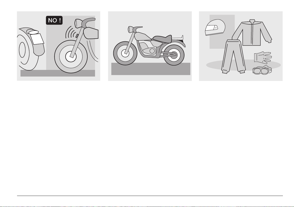
#,/4().'
Before starting, always wear a correctly
fastened crash helmet. Make sure that it is
homologated, in good shape, of the right
size and that the visor is clean.
Wear protective clothing, preferably in light
and/or reflecting colours. In this way you
will make yourself more visible to the other
drivers, thus notably reducing the risk of
being knocked down, and you will be more
protected in case of fall.
This clothing should be very tight-fitting
and fastened at the wrists and ankles;
strings, belts and ties should not be hanging loose; prevent these and other objects
from interfering with driving by getting entangled with moving parts or driving mechanisms.
use and maintenance ETV mille Caponord
9
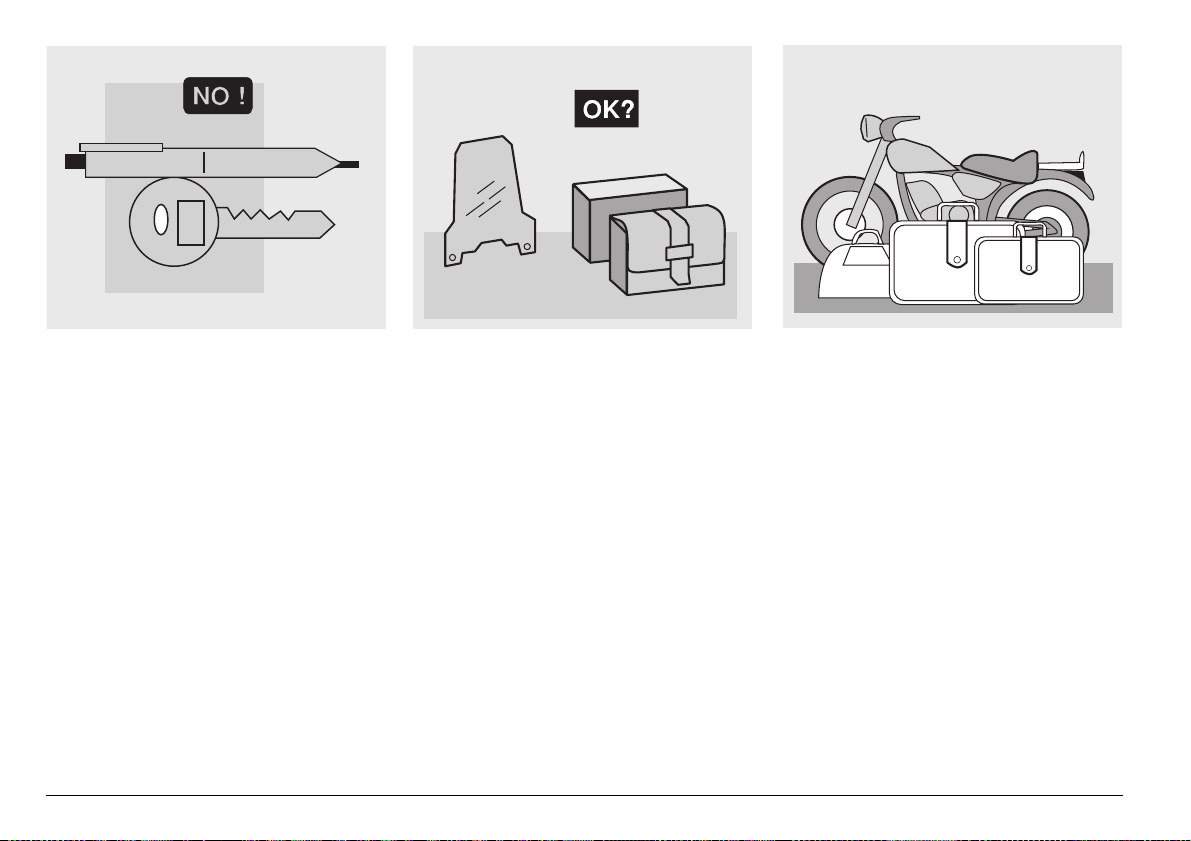
Do not keep objects that can be dangerous
in case of fall, for example pointed objects
like keys, pens, glass vials etc. in your
pockets (the same recommendations also
apply to passengers).
use and maintenance ETV mille Caponord
10
!##%33/2)%3
The owner of the vehicle is responsible for
the choice, installation and use of any accessory.
Avoid installing accessories that cover
horns or lights or that could impair their
functions, limit the suspension stroke and
the steering angle, hamper the operation of
the controls and reduce the distance from
the ground and the angle of inclination in
turns.
Avoid using accessories that hamper access to the controls, since this can prolong
reaction times during an emergency.
Big fairings and windshields installed on
the vehicle may produce aerodynamic forces that affect the stability of the vehicle, especially when riding at high speed.
Make sure that the equipment is well fastened to the vehicle and not dangerous
during driving.
Do not install electrical devices and do not
modify those already existing to avoid electrical overloads, because the vehicle could
suddenly stop or there could be a dangerous current shortage in the horn and in the
lights.
aprilia recommends the use of genuine
accessories (aprilia genuine accessories).
,/!$
Be careful and moderate when loading
your luggage. Keep any luggage loaded as
close as possible to the center of gravity of
the vehicle and distribute the load uniformly on both sides, in order to reduce umbalance to the minimum. Furthermore, make
sure that the load is firmly secured to the
vehicle, especially during long trips.
KG!
Avoid hanging bulky, heavy and/or dangerous objects on the handlebars, mudguards
and forks, because the vehicle might respond more slowly in turns and its manoeuvrability could be unavoidably impaired.
Do not place bags that are too bulky on the
vehicle sides and do not ride with the crash
helmet, because they could hit people or
obstacles, making you lose control of the
vehicle.
Do not carry any bag if it is not tightly secured to the vehicle.
Do not carry bags which protrude too much
from the luggage-rack or which cover the
lights, horn or indicators.
Do not carry animals or children on the
glove compartment or on the luggage rack.
Do not exceed the maximum load allowed
for each side-bag.
When the vehicle is overloaded, its stability
and its manoeuvrability can be compromised.
use and maintenance ETV mille Caponord
11
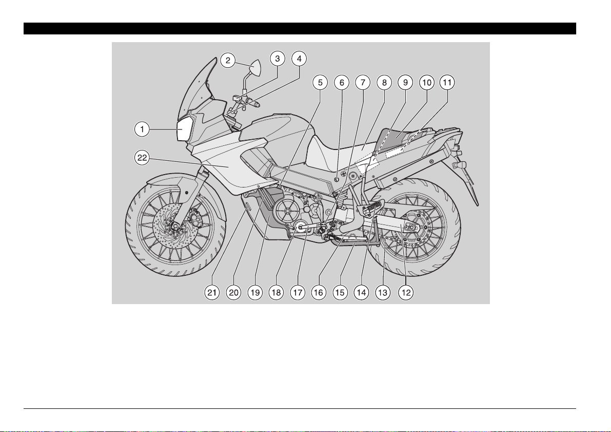
!22!.'%-%.4/& 4(% -!).%,%-%.43
+%9
1) Headlight
2) Left rear-view mirror
3) Clutch fluid reservoir
4) Ignition switch/steering
lock/parking lights
5) Engine oil tank cap
6) Saddle lock
7) Rider left footrest
8) Rider saddle
9) Battery
10) Passenger seat
11) Electronic unit
12) Rear fork
13) Drive chain
14) Passenger left footrest
(snapping, closed/open)
15) Centre stand m
16) Side stand
17) Shifting lever
18) Engine oil filter
19) Engine oil tank
20) Engine oil level
21) Horn
22) Left fairing
use and maintenance ETV mille Caponord
12
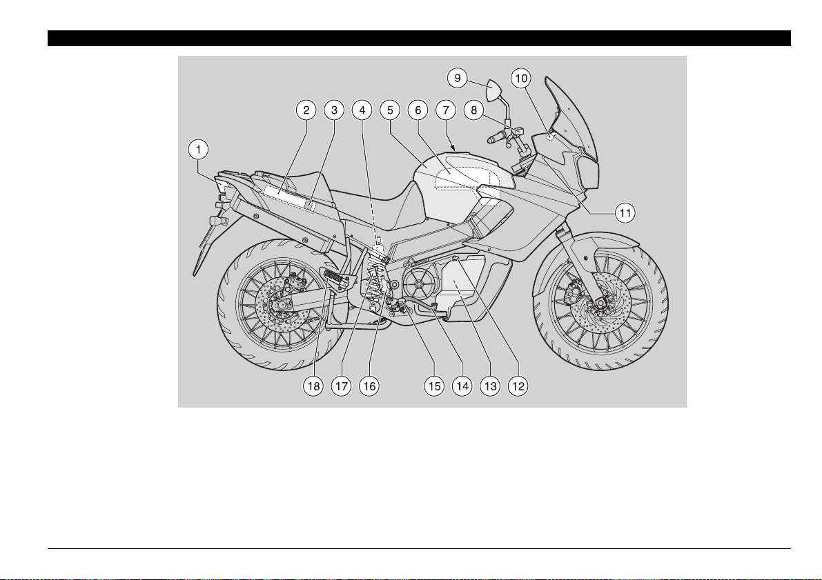
+%9
1) Rear light
2) Glove/tool kit compartment
3) Main fuse carrier (30A)
4) Rear shock absorber
5) Fuel tank
6) Air cleaner
7) Fuel tank filler cap
8) Front brake fluid tank
9) Right rear-view mirror
10) Secondary fuse carrier
(15A)
11) Air temperature sensor
12) Coolant expansion tank cap
13) Coolant expansion
14) Rear brake control lever
15) Rider right footrest
16) Rear brake pump
17) Rear brake fluid tank
18) Passenger right footrest
(snapping, closed/open)
use and maintenance ETV mille Caponord
13
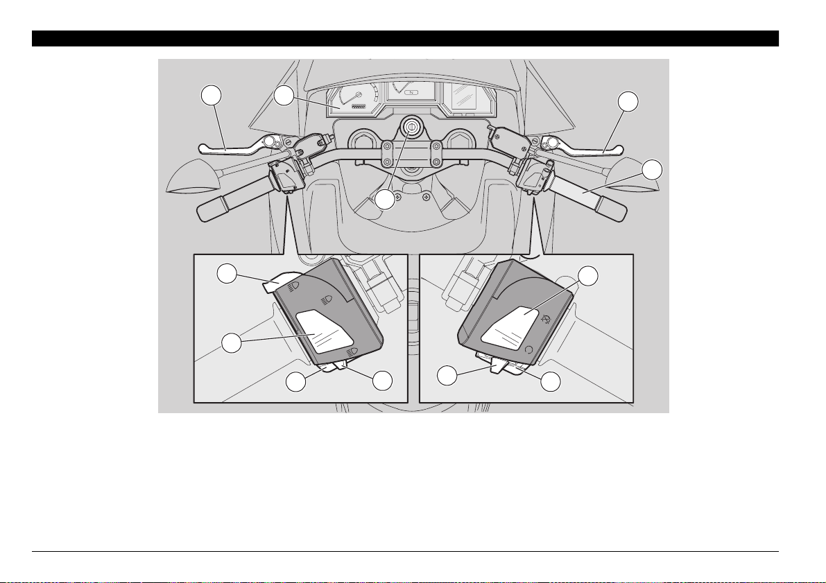
!22!.'%-%.4/& 4(% ).3425-%.43#/.42/,3
6
5
4
140
120
100
80
60
6
7
40
20
0
3
160
180
2
200
Km/h
1
220
0
240
260
280
Km
1
7
8
9
A
10
11
12
-1
min
x1000
TAIR
L
gal
SERVICE
C
F
TIME
ENGINE
EFI
CONTROL
SETMODE
DIAGNOSIS
8
9
5
4
3
2
+%9
1) Ignition switch/steering lock/parking lights (2 - 1 - & - :)
2) Direction indicator switch (6)
3) Horn push button (*)
4) Dimmer switch (8 - 7)
5) High beam signaller push button (7)/LAP push button (multifunc-
tion)
6) Clutch lever
use and maintenance ETV mille Caponord
14
10
12
11
7) Instruments and indicators
8) Front brake lever
9) Throttle grip
10) Engine stop switch (2 - 1)
11) Start push button (+)
12) Light switch (( - ' -
•
) (not provided for e)
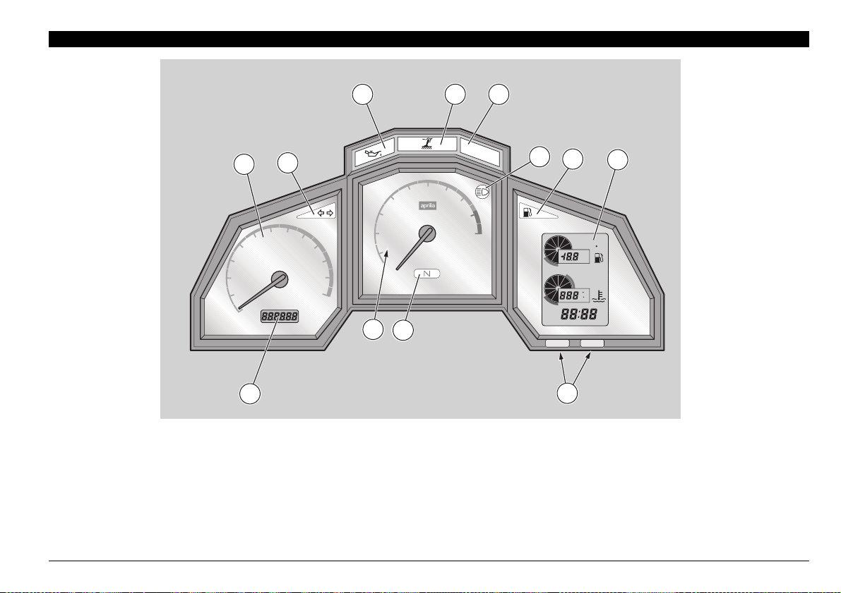
).3425-%.43!.$ ).$)#!4/23
1
60
40
20
2
120
140
100
km/h
160
180
200
220
240
km
80
0
12
+%9
1) Speedometer
2) Green direction indicator warning light LED (6)
3) Red engine oil pressure warning light LED (.)
4) Amber side stand down warning light LED (Æ)
5) Red diagnostic warning light LED (EFI)
6) Blue high beam warning light LED (7)
7) Amber low fuel warning light LED (-)
3
5
4
4
6
7
3
2
1
MAGNETI
0
MARELLI
11
10
8
min
x1000
9
10
5
EFI
-1
6
TIME
EFI
7
SERVICE
C
F
SETMODE
TAIR
8
ENGINE
CONTROL
DIAGNOSIS
9
8) Right multifunction digital display (fuel level-air temperature coolant temperature - clock/injection system error codes)
9) SET and MODE programming buttons
10) Green neutral indicator warning light LED (/)
11) Revolution counter
12) Left digital display (odometer)
use and maintenance ETV mille Caponord
15
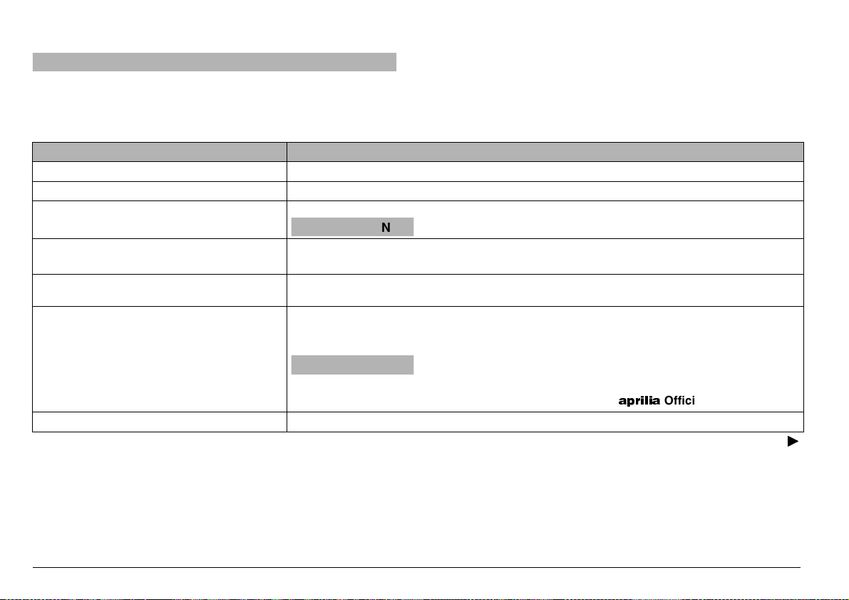
).3425-%.43!.$).$)#!4/234!",%
aCAUTION
The switching km/mi °C/°F is set and fixed by APRILIA in the
vehicle production phase, according to the country of destination.
This setting cannot be modified successively.
Description Function
Direction indicator warning light LED
High beam warning light LED
Revolution counter rpm
Amber low fuel warning light LED
Side stand down war warning light
LED
Engine oil pressure warning light
LED
Neutral indicator warning light LED
Blinks when the direction indicators are on.
6
Comes on when the high beam bulbs are on or when the headlight signaller is operated.
7
Indicates the number of revolutions of the engine per minute.
aCAUTION
Comes on when the quantity of fuel left in the tank is about 4 ± 1 L.
-
In this case, top up as soon as possible, see p. 29 (FUEL).
Comes on when the side stand is down.
Æ
Comes on whenever the ignition switch is in position “2” and the engine is not running, thus
checking the functionality of the LED.
If the light LED does not come on in this phase, contact an aprilia Official Dealer.
.
aCAUTION
this means that the engine oil pressure in the circuit is insufficient.
In this case, stop the engine immediately and contact an
Comes on when the gear is in neutral.
/
NOTE Whenever the ignition switch is turned to position “2”,
all the LED warning lights, including the dashboard lighting
LEDs, come on on the dashboard for approximately three seconds, thus testing the correct operation of the LEDs.
Never exceed the engine max. speed rate, see p. 54 (RUNNING-IN).
If the engine oil pressure warning light LED “
the start or comes on during the normal operation of the engine,
APRILIA
.” remains on after
Official Dealer.
Follow
ã
use and maintenance ETV mille Caponord
16
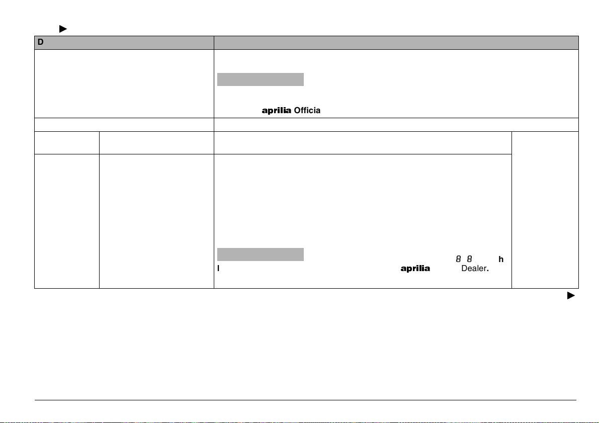
Follow
ã
Description Function
Comes on for approximately three seconds whenever the ignition switch is turned to position
2”, thus testing the correct operation of the LED.
“
Diagnostic warning light LED EFI
Speedometer (km/h) It indicates the driving speed.
Digital display
(left side)
Multifunction
digital display
(right side)
Odometer (km - mi) Indicates the partial or total number of kilometres (miles) covered.
Fuel level indicator
aCAUTION
operation of the engine, this means that the electronic unit has detected an anomaly. In
many cases, the engine keeps running with reduced performance levels; immediately
contact an
Indicates the fuel level in the tank.
The fuel quantity is shown by the indicator range (analog display).
When the fuel tank is full, the indicator range is completely on.
As the fuel level decreases, the marked area of the indicator range decreases
accordingly.
When no segment of the indicator range is on and the low fuel warning light
LED blinks, this means that the quantity of fuel left in the tank amounts to less
-
than 5 ± 1
In this case, top up as soon as possible, see p. 29 (FUEL).
APRILIA
L.
aCAUTION
low fuel warning light LED blinks, contact an
If the diagnostic warning light LED “EFI” comes on and blinks
when the engine is started or starts blinking during the normal
Official Dealer.
When no segment of the indicator range is on, the
numerical display blinks indicating “
NOTE The digital sector is used to display the air temperature (T°AIR).
APRILIA
Official Dealer.
” and the
To alternate the
data displayed,
see p. 20 (SETTING BUTTONS).
Follow
ã
use and maintenance ETV mille Caponord
17
Follow
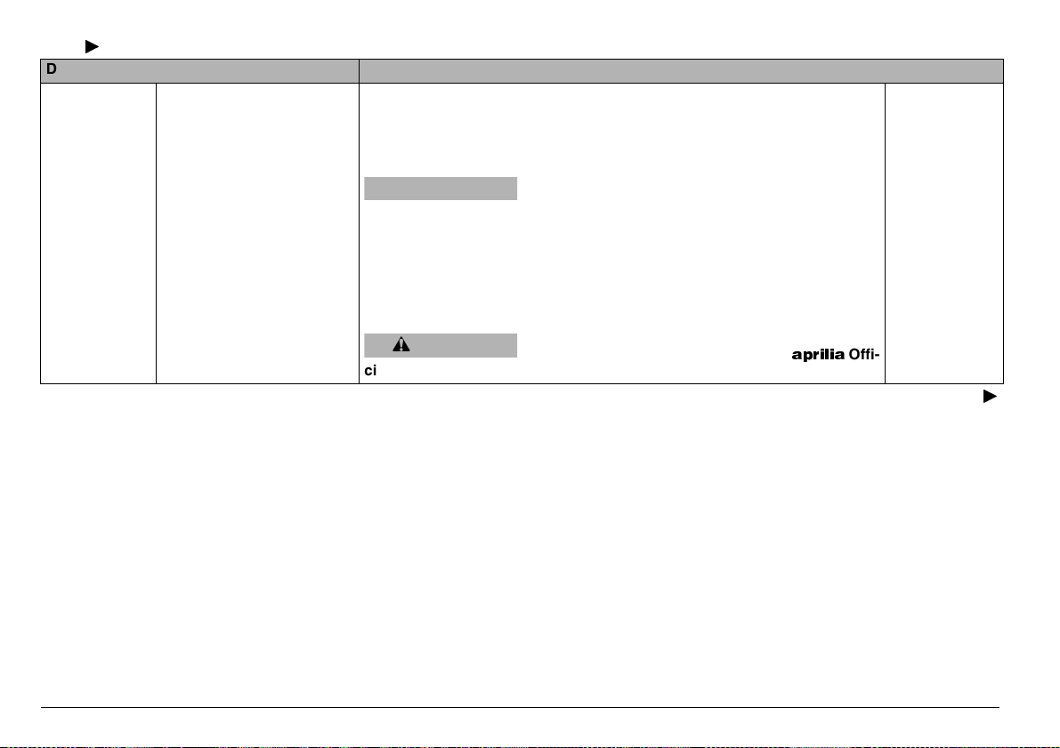
ã
Description Function
Displays the air temperature.
This temperature is displayed in the numerical sector (numerical display).
With temperatures under -20 °C (-4 °F) the writing “
-20 °C (-68 °F) and 50 °C (122 °F) the exact temperature value is displayed;
over 50 °C (122 °F) the writing “” (“”) is displayed.
aWARNING
Multifunction
digital display
(right side)
Air temperature
indicator
moderate speed, since there may be ice formation, and avoid abrupt
brakings or manoeuvres that may cause loss of grip.
T°AIR
When the air temperature is equal to or lower than 3 °C (37.4 °F), the display
blinks indicating the temperature for ten seconds [even if in the meantime the
temperature increases and exceeds 3 °C (37.4 °F)].
If the temperature remains under 3 °C (37.4 °F), the procedure is repeated
every five minutes for three times.
aCAUTION
cial Dealer.
” is displayed; between
When the digita l display bli nks ind ica ting a temperature equal to or lower than 3°C (37.4 °F), drive at
When the digital display blinks showing the writing
BB” or the writing “”, contact an
“
APRILIA
Offi-
To alter nate th e
data displayed,
see p. 20 (SETTING BUTTONS).
Follow
ã
use and maintenance ETV mille Caponord
18
Follow
ã
Description Function
Indicates the temperature of the coolant in the engine, see p. 20 (SETTING
BUTTONS).
The temperature is indicated by the indicator range (analog display) and by
the value expressed in °C (°F) (digital display).
Up to 35 °C (97 °F) the writing “
aCAUTION
To lower the coolant temperature the cooling fans operate even when
the engine is not running and are switched off automatically.
aCAUTION
sly damaged.
If a temperature of 116 – 125 °C (241 – 257 °F) is displayed and the secondlast segment of the indicator range blinks, stop the engine, wait for the cooling
fans to be switched off and check the coolant level, see p. 38 (COOLANT).
If a temperature of 126 – 135 °C (259 – 275 °F) is displayed and the last two
segments of the indicator range blink, stop the vehicle and let the engine idle
for approximately two minutes, thus allowing the coolant to circulate regularly
in the system; then, press the engine stop switch to position “
the coolant level, see p. 38 (COOLANT). If the situation on the dashboard remains the same after the coolant level has been checked, do not start the
vehicle and contact an aprilia Official Dealer.
After the first 1000 km (625 mi) and successively every 7500 km (4600 mi),
the word “SERVICE” appears.
aCAUTION
regular service intervals chart, see p. 60 (REGULAR SERVICE INTERVALS CHART).
Multifunction
digital display
(right side)
Coolant temperature indicator (°C/°F)
Service operation indicator “SERVICE”
)
” is displayed.
The switching on and off of the cooling fans does
not depend on the position of the ignition switch.
If the maximum allowed temperature (125°C or
257 °F) is exceeded, the engine may be seriou-
1” and check
In this case contact an
who will carry out the operations indicated in the
APRILIA
Official Dealer,
To alternate the
data displayed,
see p. 20 (SETTING BUTTONS).
Clock
Indicates the hour and minutes according to the presetting, see p. 20 (SETTING BUTTONS).
use and maintenance ETV mille Caponord
19

SET
2
1
120
140
100
160
PUSH
80
60
40
20
0
180
km/h
200
220
240
km
5
4
3
2
1
0
3
EFI
6
7
8
9
10
-1
min
x1000
MAGNETI
MARELLI
7
4
5
T AIR
6
TAIR
9
C
TIME
ENGINE
CONTROL
DIAGNOSIS
SETMODE
8
C
TIME
EFI
MODE
ENGINE
CONTROL
DIAGNOSIS
SET
10
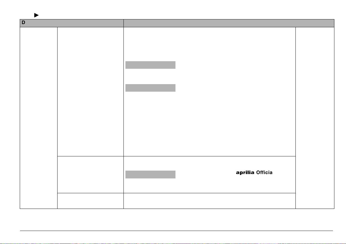
3%44).'"544/.3
aWARNING
The operations described below must
be carried out with the vehicle at rest.
Performing these operations while the
vehicle is running may be cause of accidents.
NOTE The following information is to be
considered as referred to the vehicle at
rest.
When the ignition key (1) is turned to position “2”, the following lights come on on
the dashboard within three seconds:
– all the warning lights LED;
– all the dashboard lighting LEDs;
– all the segments on the left display;
– all the segments and writings on the
right multifunction display;
– the pointers of the indicators move to the
bottom of the indicator range;
thus testing the operation of LEDs, writings, segments and instruments.
use and maintenance ETV mille Caponord
20
After three seconds, the engine oil pressure warning light LED “.” (2) remains
on on the dashboard (and will remain on
until the engine is started) and the following will appear on the displays:
– total number of kilometres covered (3);
– fuel quantity (4);
– air temperature (5);
– coolant temperature (6) [up to 35 °C
(95°F) the writing “---” is displayed];
– hour and minutes (7).
ADJUSTING THE DASHBOARD
LIGHTING
It is possible to select three different levels
for the dashboard lighting: 100%; 60%;
25%.
For the adjustment, proceed as follows:
◆ Move the light switch (8) to position
“'”;
ì Bring the dimmer switch “8 - 7” (9)
to position “8”.
NOTE Three seconds after the last se-
lection, the button SET returns to the
switching mode total/partial kilometres
(miles) odometer.
◆ Turn the ignition switch (1) to position
“2” and, within three seconds, press the
button SET (10) in sequence, thus obtaining the three lighting levels.
◆ Select the desired lighting level.
SWITCHING FROM km/mi, °C/°F
aCAUTION
The switching km/mi, °C/°F is set and
fixed by APRILIA in the vehicle production phase, according to the country of
destination.
This setting cannot be modified successively.
1
2
3
4
5
6
7
8
9
10
0
km
km/h
DIAGNOSIS
CONTROL
ENGINE
C
SETSETMODE
TIME
1
2
TAIR
SET
MODE
TAIR
L
4
TIME
MODE
5
C
ENGINE
CONTROL
SET
DIAGNOSIS
13
SWITCHING FROM TOTAL TO PARTIAL
KILOMETRE (MILE) ODOMETER
Left display
◆ Press and release the button SET (1);
the relevant total partial or total kilometres (miles) covered will appear on the
display.
NOTE Whenever the ignition switch is
turned to position “2”, the display always
indicates the total number of kilometres
(miles) covered.
To set the partial kilometre (mile) odometer to zero, proceed as follows:
◆ Display the partial number of kilometres
◆ Press the button SET (1) for more than
three seconds; the segments (2) are set
to zero.
covered, see above.
SETTING THE CLOCK (HOURS AND
MINUTES)
NOTE The setting of the clock can be
carried out only with the vehicle at rest.
◆ Press the MODE (3) push button for
more than three seconds, the segments
corresponding to the hours (4) will blink.
NOTE If the button SET (1) is pressed
and released, the data are changed one by
one; if the button SET (1) is kept pressed,
the data change scrolling quickly and cyclically.
◆ Press the SET (1) push button and se-
lect the desired hour.
◆ To confirm the time setting, press and re-
lease the button MODE (3), and the
minute segments (5) will blink.
◆ Press the SET (1) push button and se-
lect the desired minutes.
◆ To confirm the minute setting, press and
release the MODE (3) push button.
NOTE If the battery is removed, the
clock is set to zero.
use and maintenance ETV mille Caponord
21
-!).).$%0%.$%.4 #/.42/,3
4
3
2
1
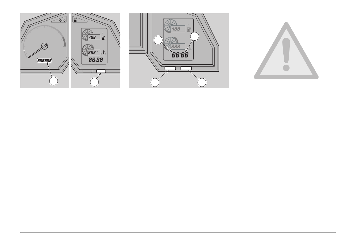
#/.42/,3/.4(%,%&40!24/&4(%
(!.$,%"!2
NOTE The electrical parts work only when the ignition switch
is in position “2”.
1) HORN PUSH BUTTON (*)
The horn is activated when the push button is pressed.
2) DIRECTION INDICATOR SWITCH (6)
To indicate the turn to the left, move the switch to the left; to
indicate the turn to the right, move the switch to the right.
To turn off the direction indicator, press the switch.
3) DIMMER SWITCH (8 - 7)
When the light switch is in position “(”: if the dimmer switch
is in position “7”, the high beam comes on; while if it is in position “8”, the low beam comes on.
3) DIMMER SWITCH (8 - 7)
When it is in position “8” the parking lights, the dashboard
light and the low beam are always on.
When it is in position “7”, the high beam comes on.
4) HIGH BEAM SIGNALLING PUSH BUTTON (7)
It makes it possible to use the high beam for signalling to
forthcoming vehicles while overtaking and in case of peril
and/or emergency.
The high beam blinking is operated by pressing the push button, independently of the position of the light switch (( - '
).
-
•
e
NOTE To disconnect the high beam blinking, release the push
button.
use and maintenance ETV mille Caponord
22
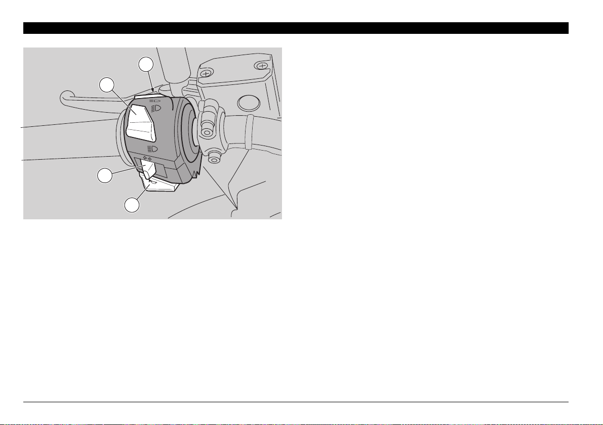
#/.42/,3/.4(%2)'(40!24/&4(%
PUSH
(!.$,%"!2
NOTE The electrical parts work only when the ignition switch
is in position “2”.
1) ENGINE STOP SWITCH (2 - 1)
aWARNING
Do not operate the engine stop switch “2 - 1” in running
conditions.
This is a safety or emergency switch.
With the switch pressed in position “2”, it is possible to start
the engine; when the switch is pressed to position “1”, the
engine stops.
aCAUTION
To stop the vehicle, use exclusively the ignition switch (A).
Leave the engine stop switch (1) in position “2” and use it
only in case of emergency.
aCAUTION
With stopped engine and ignition switch in position “2”, the
battery may discharge.
If the engine stop switch must be used (1), immediately afterwards turn the ignition switch (A) to position “1”.
2) LIGHT SWITCH (( - ' -
) (not provided for e)
•
When the light switch is in position “•”, the lights are off; when
the switch is in position “'”, the parking lights and the dash-
board light are on; when the switch is in position “(”, the
parking lights, the dashboard light and the low beam are on.
The high beam can be operated by means of the dimmer
switch.
1
A
H
S
U
P
2
3
3) START PUSH BUTTON (+)
When the start push button “+” is pressed, the starter makes
the engine run. For the starting, see p. 48 (STARTING).
use and maintenance ETV mille Caponord
23
1
2
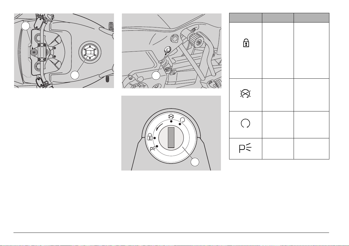
)'.)4)/.37)4#(
The ignition switch (1) is positioned on the
upper plate of the steering column.
NOTE The key operates the ignition
switch/steering lock, the fuel tank lock (2)
and the passenger seat lock (3).
Two keys are supplied together with the
vehicle (one spare key).
NOTE Do not keep the spare key on the
vehicle.
3
PUSH
Position Function Key removal
The steering is locked. It is
It is possible
to remove the
key.
neither pos-
Steering
lock
sible to start
the engine,
nor to switch
on the
lights.
Neither the
engine, nor
the lights
It is possible
to remove the
key.
can be
switched on.
The engine
and the
lights can be
It is not possi-
ble to remove
the key.
switched on.
The parking
I
Z
D
A
1
lights are
on.
It is possible
to remove the
key.
use and maintenance ETV mille Caponord
24
P
U
S
H
PUSH
1
PUSH
1
H
S
U
P
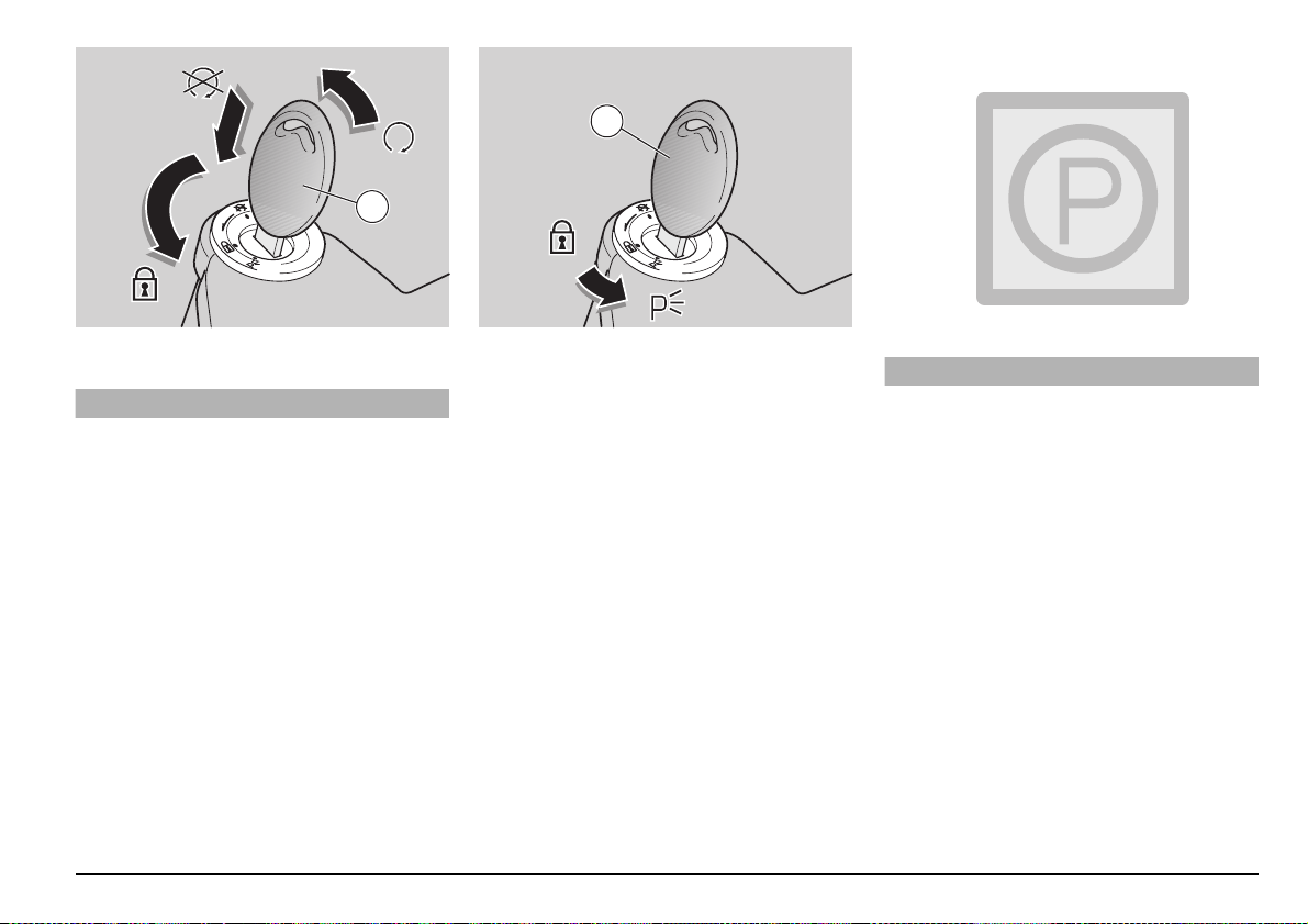
34%%2).',/#+
aWARNING
Never turn the key to position “&” in
running conditions, in order to avoid
losing control of the vehicle.
OPERATION
To lock the steering:
◆ Turn the handlebar completely leftwards.
◆ Turn the key to position “1”.
◆ Press the key and rotate it to position “&”.
NOTE If it is necessary to switch on the
parking lights, see p. 25 (PARKING
LIGHTS).
◆ Extract the key.
0!2+).',)'(43
The vehicle is provided with front and rear
parking lights. Even if it is always advisable
to park the vehicle in the appropriate parking areas and in any case in illuminated
places, the parking lights are very useful
when it is necessary to park the vehicle in a
dark or badly illuminated area, or in any
case when the vehicle must be visible.
OPERATION
To switch on the parking lights, proceed
as follows:
◆ Lock the steering without extracting the
key (1), see p. 25 (STEERING LOCK).
◆ Turn the key (1) to position “:” (PARK-
ING).
◆ Make sure that both parking lights (front
and rear) are on and operate correctly.
◆ Remove the key (1).
aCAUTION
Do not leave the parking lights on for
long periods, in order to avoid the wear
of the battery due to the current consumption required by the lights. The
complete wear of the battery makes it
impossible to start the vehicle.
use and maintenance ETV mille Caponord
25
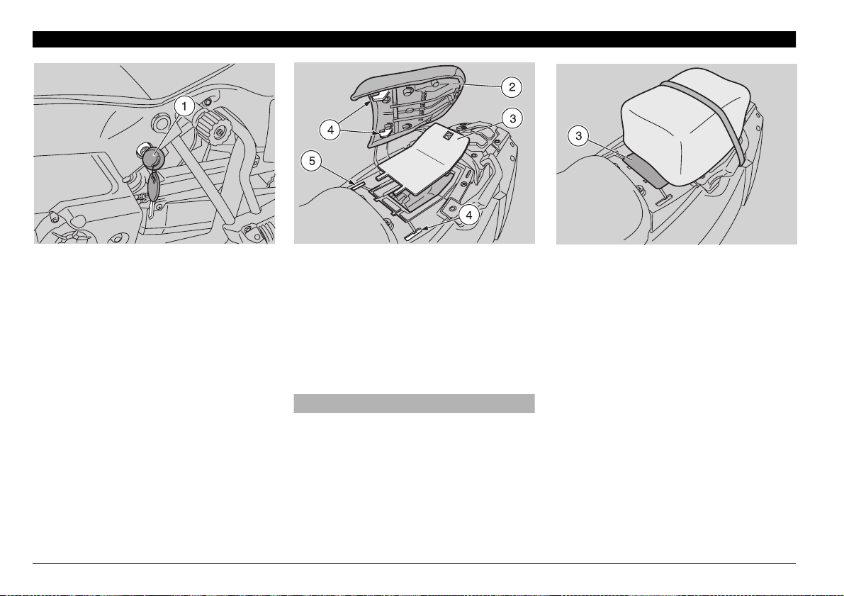
!58),)!29%15)0-%.4
5.,/#+).',/#+).'4(%
0!33%.'%23%!4
◆ Position the vehicle on the stand, see p.
56 (POSITIONING THE VEHICLE ON
THE STAND).
◆ Introduce the key (1) in the seat lock.
◆ Rotate the key (1) clockwise, lift and
withdraw the seat (2) from behind.
NOTE The glove/tool kit compartment is
positioned under the passenger seat.
To reach it, proceed as follows:
◆ Remove the glove/tool kit compartment
cover (3).
use and maintenance ETV mille Caponord
26
To lock the seat (2), proceed as follows:
NOTE Before lowering and locking the
seat (2), make sure that you have not left
the key in the glove/tool kit compartment.
◆ Insert the two front couplings (4) in the
relevant seats (5).
◆ Lower and press the passenger seat (2),
making the lock snap.
aWARNING
Before leaving, make sure that the seat
(2) is properly locked.
5.,/#+).',/#+).'4(%
',/6%4//,+)4#/-0!24-%.4
#/6%2
If a larger surface for the luggage is needed, when the rider travels alone the passenger seat can be removed. To carry out
this operation, it is necessary to lock the
glove/tool kit compartment cover (3).
In this case:
◆ Remove the passenger seat, see p. 26
(UNLOCKING/LOCKING THE PASSENGER SEAT).
◆ Remove the lock coupling (6) from its
seat.
◆ Insert the lock coupling (6) and fit it cor-
rectly in the appropriate seat (7) on the
glove/tool kit compartment cover (see
figure).
◆ Correctly position the glove/tool kit com-
partment cover (3) in its seat.
10
6
6
7
◆ Lower and press the glove/tool kit com-
partment cover (3), making the lock
snap.
Maximum allowed weight: 9 kg.
aWARNING
The luggage must not be excessively
bulky and it must be firmly anchored to
the passenger grab rails.
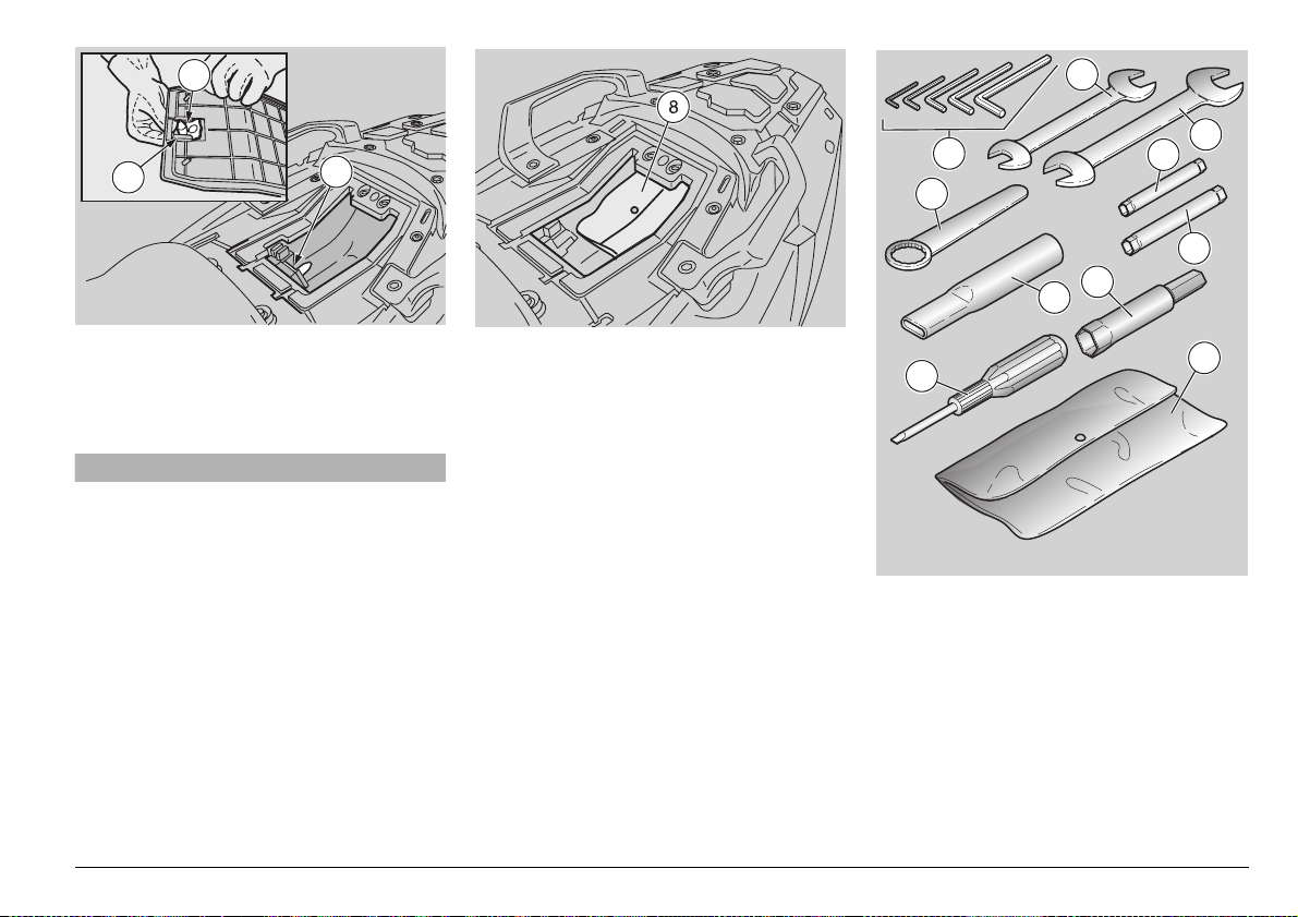
',/6%4//,+)4#/-0!24-%.4
To reach the glove/tool kit compartment,
proceed as follows:
◆ Remove the saddle, see p. 26 (UNLOCK-
ING/LOCKING THE PASSENGER
SEAT).
The tool kit (8) includes:
– 2.5 – 3 – 4 – 5 – 6 mm bent hexagon
spanners (9);
– 8 – 10 mm double fork spanner (10);
– 13 – 14 mm double fork spanner (11);
– 26 mm simple box spanner (12);
– extension for simple box spanners (13);
– 6 – 7 mm double socket spanner (14);
– 8 – 10 mm double socket spanner (15);
– 16 mm socket spanner for spark plug
(16);
– double-ended, cross-/cut-headed screw-
driver (17);
– tool case (18);
9
12
13
17
14
16
Maximum allowed weight: 1.5 kg.
11
15
18
use and maintenance ETV mille Caponord
27
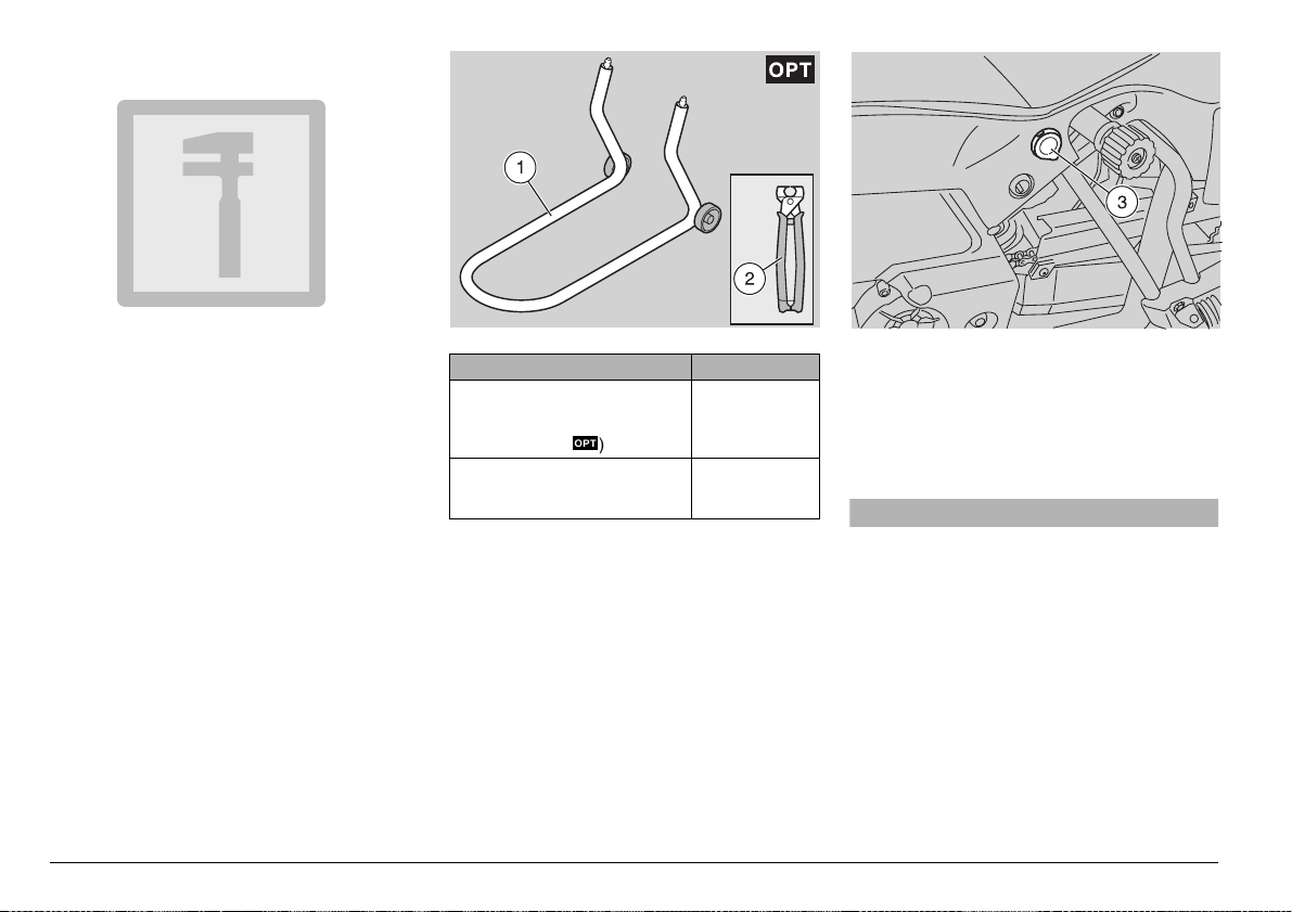
30%#)!,4//,3m
To perform some specific operations, it is
advisable to use the following special tools
(to be requested to an aprilia Official Deal-
er):
use and maintenance ETV mille Caponord
28
Tool Operations
Front support stand (1), see p.
74 (POSITIONING THE VEHICLE ON THE FRONT SUPPORT STAND
Click clamp (2) installation pliers, see p. 62 (CLICK
CLAMPS).
m
).
Front wheel disassembly.
Click clamp installation.
/54,%4
This vehicle is provided with an outlet (3)
for plugs with 20 mm diameter.
Do not connect any electrical equipment with
electrical input over 180 W or voltage different from 12 V to the outlet.
aWARNING
Do not use the outlet while the vehicle
is running, since the plug may come off
and fall on the moving parts of the vehicle.
!##%33/2)%3
The vehicle may be equipped with the following accessories (to be requested to the
aprilia Official Dealer):
– centre stand m;
– side bags m;
– bag on the tank m;
– rear case m.
-!).#/-0/.%.43
MAX
MAX
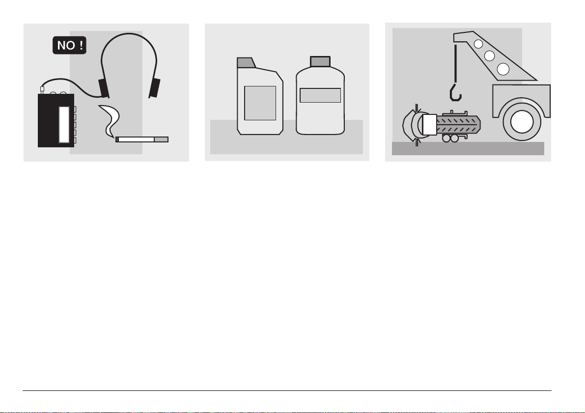
&5%,
aWARNING
The fuel used for internal combustion
engines is extremely inflammable and
in particular conditions it can become
explosive.
It is important to carry out the refuelling
and the maintenance operations in a
well-ventilated area, with the engine off.
Do not smoke while refuelling or near
fuel vapours, in any case avoid any contact with naked flames, sparks and any
other heat source to prevent the fuel
from catching fire or from exploding.
Further, prevent fuel from flowing out of
the fuel filler, as it could catch fire when
getting in contact with the red-hot surfaces of the engine.
In case some fuel has accidentally been
spilt, make sure that the area has completely dried and before starting the vehicle verify that there is no fuel inside
the fuel filler neck.
Since petrol expands under the heat of
the sun and due to the effects of sun radiation, never fill the tank to the brim.
Screw the plug up carefully after refuelling. Avoid any contact of the fuel with
the skin and the inhalation of vapours;
do not swallow fuel or pour it from a receptacle into another by means of a
tube.
DO NOT DISPOSE OF FUEL IN THE ENVIRONMENT.
KEEP AWAY FROM CHILDREN.
Use only premium grade unleaded petrol,
min. O.N. 95 (N.O.R.M.) and 85
(N.O.M.M.).
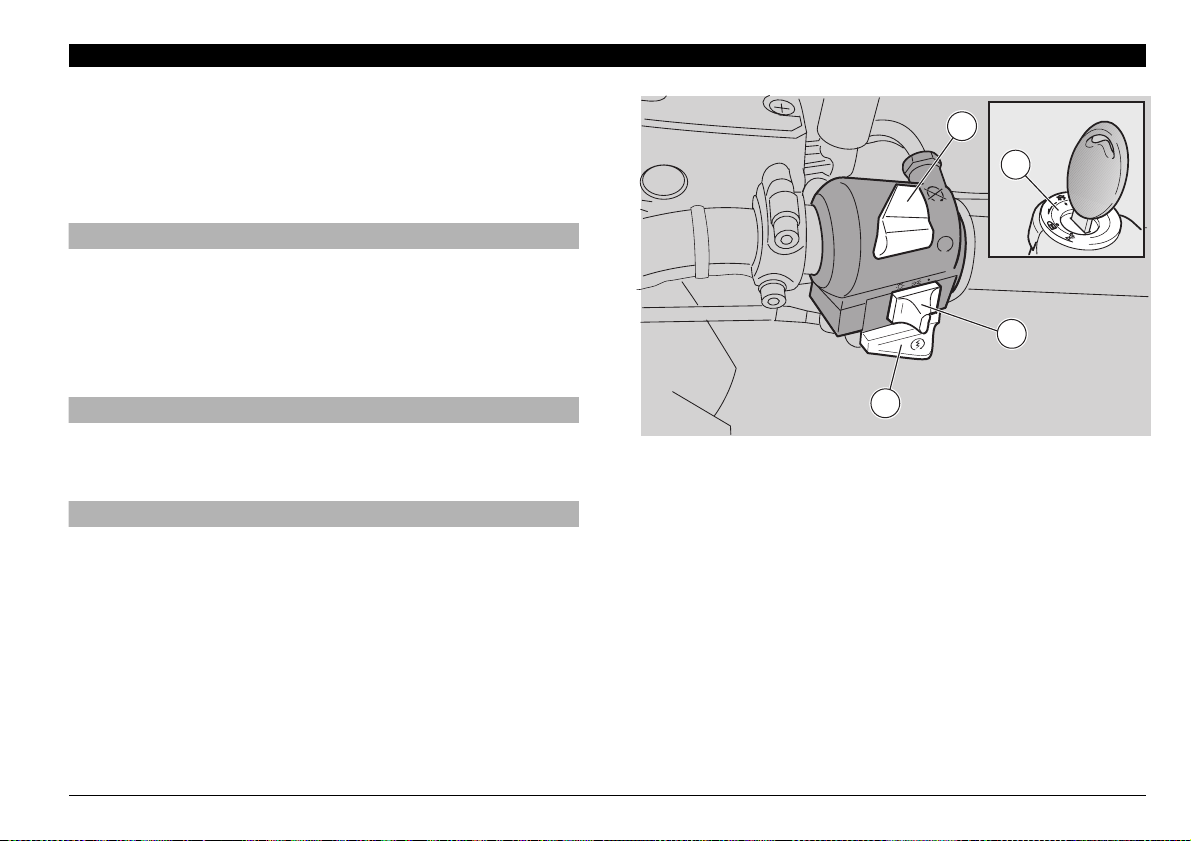
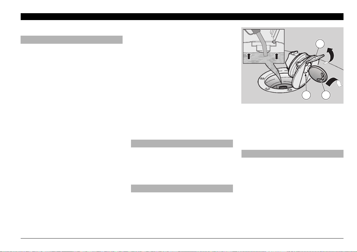
To refuel, proceed as follows:
◆ Raise the flap (1).
◆ Insert the key (2) in the tank plug lock
(3).
◆ Turn the key clockwise, pull and open
the fuel flap.
FUEL TANK CAPACITY (reserve included): 25
TANK RESERVE: 5 ± 1 L
L
aCAUTION
Do not put additives or other substances into the fuel.
If you use a funnel or other similar
items, make sure that they are perfectly
clean.
aWARNING
Do not fill the tank completely; the maximum fuel level must remain below the
lower edge of the filler neck (see figure).
◆ Refuel.
MAX
After refuelling:
MAX
1
3
2
NOTE The cap can be closed only when
the key (2) is inserted.
◆ With inserted key (2), close the cap by
pressing it.
aWARNING
Make sure that the cap is properly
closed.
◆ Withdraw the key (2).
◆ Close the flap (1).
use and maintenance ETV mille Caponord
29
"2!+%&,5)$RECOMMENDATIONS
NOTE This vehicle is provided with front
and rear disc brakes, with separate hydraulic circuits.
The following information refers to a single
braking system, but is valid for both.
aWARNING
Sudden resistance or clearance problems on the brake lever may be due to
troubles in the hydraulic system.
For any doubt regarding the perfect
functioning of the braking system and
in case you are not able to carry out the
usual checking operations, contact
your APRILIA Official Dealer.
use and maintenance ETV mille Caponord
30
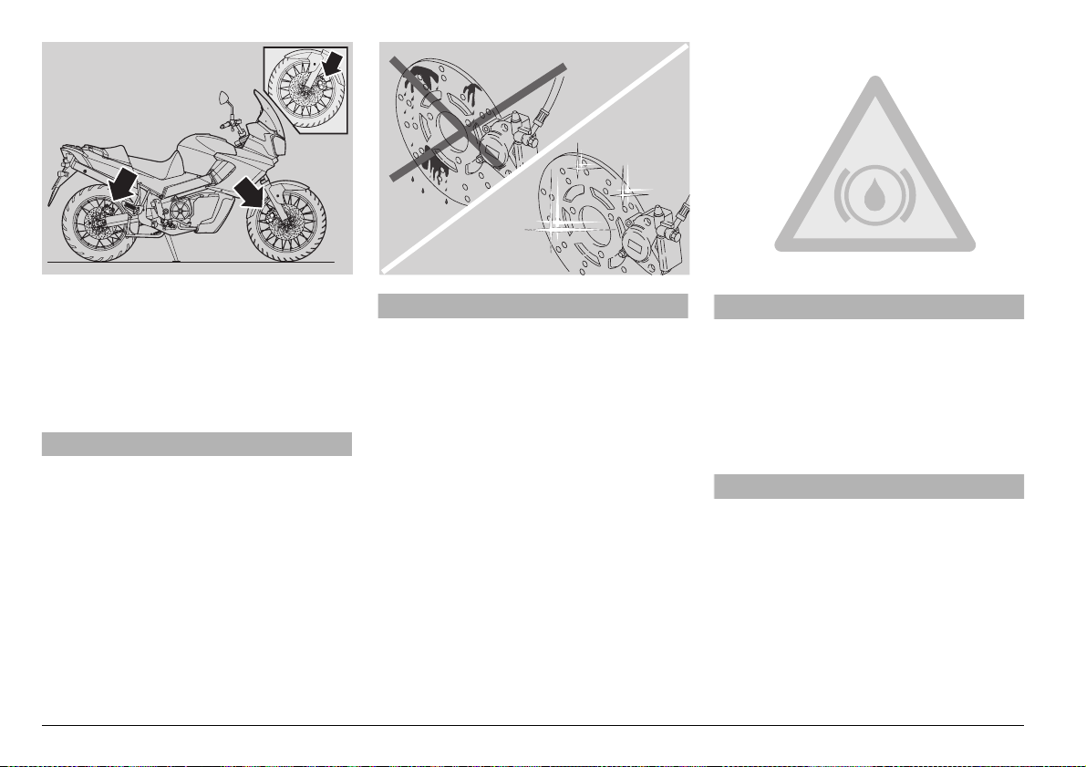
aWARNING
Make sure that the brake discs are neither oily nor greasy, especially after
maintenance or checking operations.
Check that the brake cables are neither
twisted nor worn out.
Prevent water or dust from accidentally
getting into the circuit.
In case maintenance operations are to
be performed on the hydraulic circuit, it
is advisable to use latex gloves.
If the brake fluid gets in contact with the
skin or the eyes, it can cause serious irritations.
aWARNING
Carefully wash the parts of your body
that get in contact with the liquid. Consult a doctor or an oculist if the liquid
gets in contact with your eyes.
DO NOT DISPOSE OF THE FLUID IN
THE ENVIRONMENT.
KEEP AWAY FROM CHILDREN.
aCAUTION
When using the brake fluid, take care
not to spill it on the plastic or painted
parts, since it can damage them.
 Loading...